differential JEEP CHEROKEE 1995 Service Owner's Manual
[x] Cancel search | Manufacturer: JEEP, Model Year: 1995, Model line: CHEROKEE, Model: JEEP CHEROKEE 1995Pages: 2198, PDF Size: 82.83 MB
Page 75 of 2198
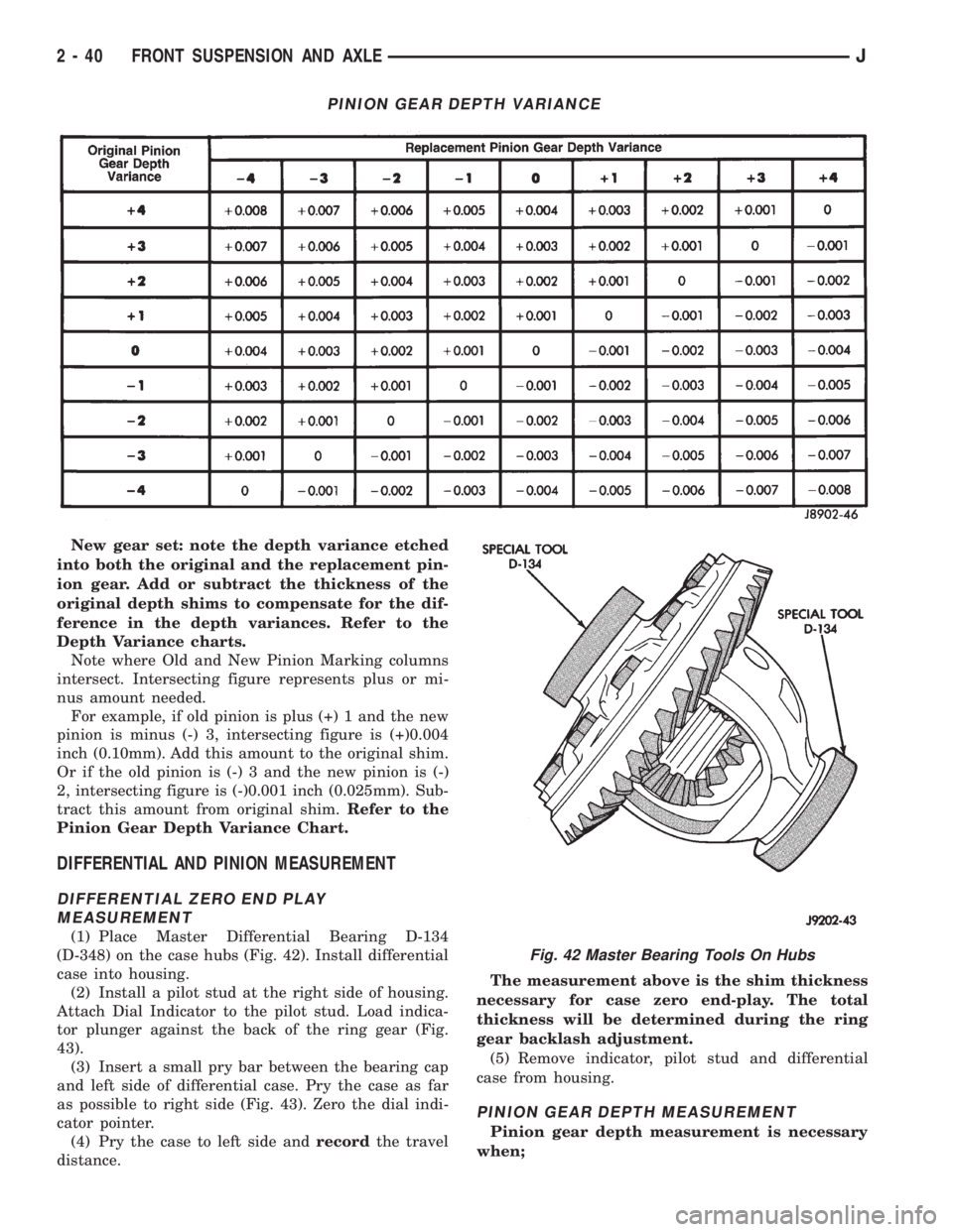
New gear set: note the depth variance etched
into both the original and the replacement pin-
ion gear. Add or subtract the thickness of the
original depth shims to compensate for the dif-
ference in the depth variances. Refer to the
Depth Variance charts.
Note where Old and New Pinion Marking columns
intersect. Intersecting figure represents plus or mi-
nus amount needed.
For example, if old pinion is plus (+) 1 and the new
pinion is minus (-) 3, intersecting figure is (+)0.004
inch (0.10mm). Add this amount to the original shim.
Or if the old pinion is (-) 3 and the new pinion is (-)
2, intersecting figure is (-)0.001 inch (0.025mm). Sub-
tract this amount from original shim.Refer to the
Pinion Gear Depth Variance Chart.
DIFFERENTIAL AND PINION MEASUREMENT
DIFFERENTIAL ZERO END PLAY
MEASUREMENT
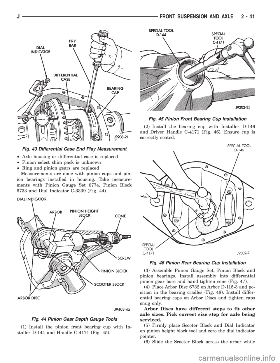
(1) Place Master Differential Bearing D-134
(D-348) on the case hubs (Fig. 42). Install differential
case into housing.
(2) Install a pilot stud at the right side of housing.
Attach Dial Indicator to the pilot stud. Load indica-
tor plunger against the back of the ring gear (Fig.
43).
(3) Insert a small pry bar between the bearing cap
and left side of differential case. Pry the case as far
as possible to right side (Fig. 43). Zero the dial indi-
cator pointer.
(4) Pry the case to left side andrecordthe travel
distance.The measurement above is the shim thickness
necessary for case zero end-play. The total
thickness will be determined during the ring
gear backlash adjustment.
(5) Remove indicator, pilot stud and differential
case from housing.
PINION GEAR DEPTH MEASUREMENT
Pinion gear depth measurement is necessary
when;
PINION GEAR DEPTH VARIANCE
Fig. 42 Master Bearing Tools On Hubs
2 - 40 FRONT SUSPENSION AND AXLEJ
Page 76 of 2198
²Axle housing or differential case is replaced
²Pinion select shim pack is unknown
²Ring and pinion gears are replaced
Measurements are done with pinion cups and pin-
ion bearings installed in housing. Take measure-
ments with Pinion Gauge Set 6774, Pinion Block
6733 and Dial Indicator C-3339 (Fig. 44).
(1) Install the pinion front bearing cup with In-
staller D-144 and Handle C-4171 (Fig. 45).(2) Install the bearing cup with Installer D-146
and Driver Handle C-4171 (Fig. 46). Ensure cup is
correctly seated.
(3) Assemble Pinion Gauge Set, Pinion Block and
pinion bearings. Install assembly into differential
pinion gear bore and hand tighten cone (Fig. 47).
(4) Place Arbor Disc 6732 on Arbor D-115-3 and po-
sition in the bearing cradles (Fig. 48). Install differ-
ential bearing caps on Arbor Discs and tighten caps
snug only.
Arbor Discs have different steps to fit other
axle sizes. Pick correct size step for axle being
serviced.
(5) Firmly place Scooter Block and Dial Indicator
on pinion height block tool and zero the dial indicator
pointer.
(6) Slide the Scooter Block across the arbor while
Fig. 43 Differential Case End Play Measurement
Fig. 44 Pinion Gear Depth Gauge Tools
Fig. 45 Pinion Front Bearing Cup Installation
Fig. 46 Pinion Rear Bearing Cup Installation
JFRONT SUSPENSION AND AXLE 2 - 41
Page 77 of 2198
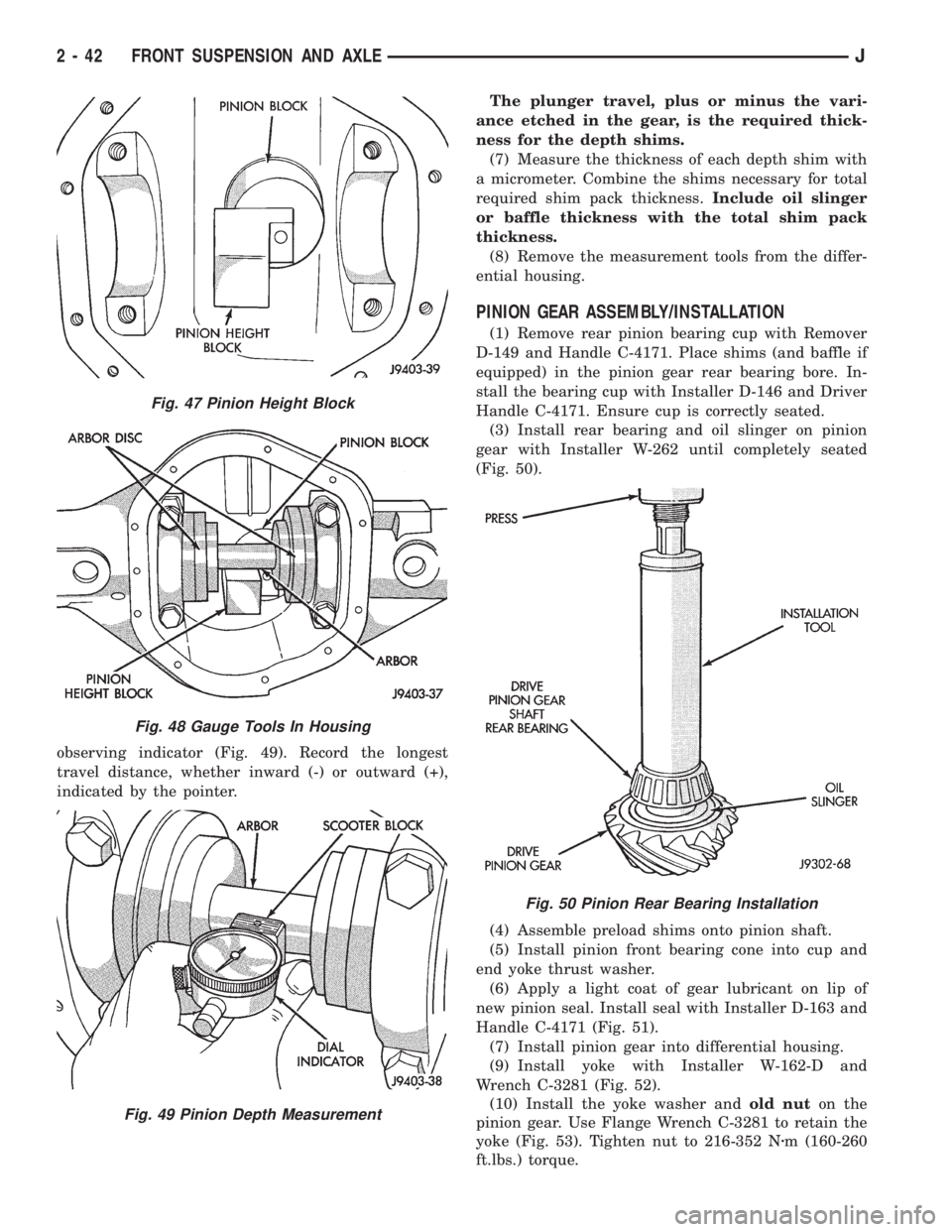
observing indicator (Fig. 49). Record the longest
travel distance, whether inward (-) or outward (+),
indicated by the pointer.The plunger travel, plus or minus the vari-
ance etched in the gear, is the required thick-
ness for the depth shims.
(7) Measure the thickness of each depth shim with
a micrometer. Combine the shims necessary for total
required shim pack thickness.Include oil slinger
or baffle thickness with the total shim pack
thickness.
(8) Remove the measurement tools from the differ-
ential housing.
PINION GEAR ASSEMBLY/INSTALLATION
(1) Remove rear pinion bearing cup with Remover
D-149 and Handle C-4171. Place shims (and baffle if
equipped) in the pinion gear rear bearing bore. In-
stall the bearing cup with Installer D-146 and Driver
Handle C-4171. Ensure cup is correctly seated.
(3) Install rear bearing and oil slinger on pinion
gear with Installer W-262 until completely seated
(Fig. 50).
(4) Assemble preload shims onto pinion shaft.
(5) Install pinion front bearing cone into cup and
end yoke thrust washer.
(6) Apply a light coat of gear lubricant on lip of
new pinion seal. Install seal with Installer D-163 and
Handle C-4171 (Fig. 51).
(7) Install pinion gear into differential housing.
(9) Install yoke with Installer W-162-D and
Wrench C-3281 (Fig. 52).
(10) Install the yoke washer andold nuton the
pinion gear. Use Flange Wrench C-3281 to retain the
yoke (Fig. 53). Tighten nut to 216-352 Nzm (160-260
ft.lbs.) torque.
Fig. 47 Pinion Height Block
Fig. 48 Gauge Tools In Housing
Fig. 49 Pinion Depth Measurement
Fig. 50 Pinion Rear Bearing Installation
2 - 42 FRONT SUSPENSION AND AXLEJ
Page 78 of 2198
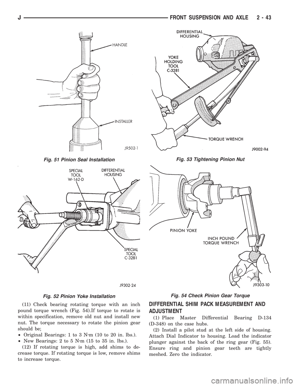
(11) Check bearing rotating torque with an inch
pound torque wrench (Fig. 54).If torque to rotate is
within specification, remove old nut and install new
nut. The torque necessary to rotate the pinion gear
should be;
²Original Bearings: 1 to 3 Nzm (10 to 20 in. lbs.).
²New Bearings: 2 to 5 Nzm (15 to 35 in. lbs.).
(12) If rotating torque is high, add shims to de-
crease torque. If rotating torque is low, remove shims
to increase torque.DIFFERENTIAL SHIM PACK MEASUREMENT AND
ADJUSTMENT
(1) Place Master Differential Bearing D-134
(D-348) on the case hubs.
(2) Install a pilot stud at the left side of housing.
Attach Dial Indicator to housing. Load the indicator
plunger against the back of the ring gear (Fig. 55).
Ensure ring and pinion gear teeth are tightly
meshed. Zero the indicator.
Fig. 51 Pinion Seal Installation
Fig. 52 Pinion Yoke Installation
Fig. 53 Tightening Pinion Nut
Fig. 54 Check Pinion Gear Torque
JFRONT SUSPENSION AND AXLE 2 - 43
Page 79 of 2198
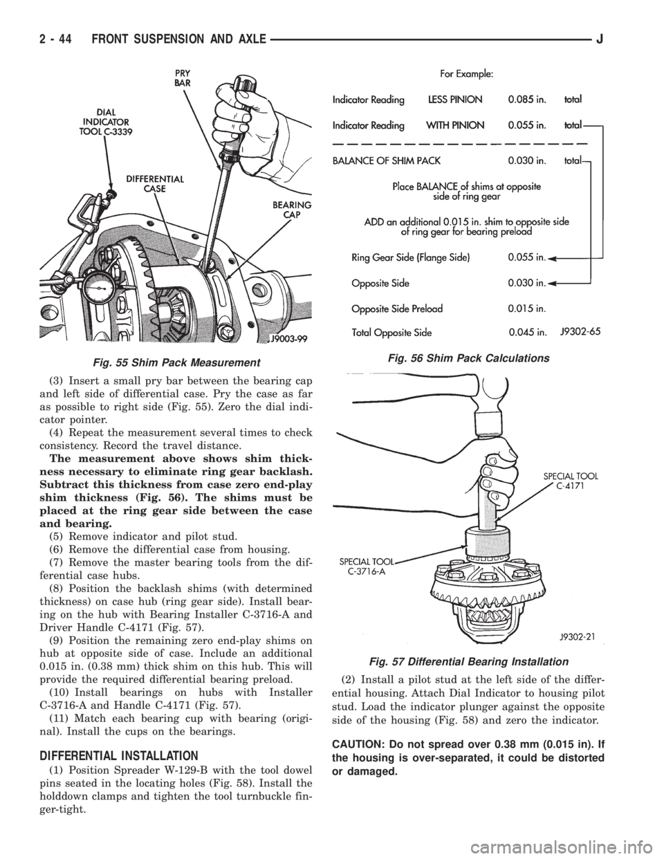
(3) Insert a small pry bar between the bearing cap
and left side of differential case. Pry the case as far
as possible to right side (Fig. 55). Zero the dial indi-
cator pointer.
(4) Repeat the measurement several times to check
consistency. Record the travel distance.
The measurement above shows shim thick-
ness necessary to eliminate ring gear backlash.
Subtract this thickness from case zero end-play
shim thickness (Fig. 56). The shims must be
placed at the ring gear side between the case
and bearing.
(5) Remove indicator and pilot stud.
(6) Remove the differential case from housing.
(7) Remove the master bearing tools from the dif-
ferential case hubs.
(8) Position the backlash shims (with determined
thickness) on case hub (ring gear side). Install bear-
ing on the hub with Bearing Installer C-3716-A and
Driver Handle C-4171 (Fig. 57).
(9) Position the remaining zero end-play shims on
hub at opposite side of case. Include an additional
0.015 in. (0.38 mm) thick shim on this hub. This will
provide the required differential bearing preload.
(10) Install bearings on hubs with Installer
C-3716-A and Handle C-4171 (Fig. 57).
(11) Match each bearing cup with bearing (origi-
nal). Install the cups on the bearings.
DIFFERENTIAL INSTALLATION
(1) Position Spreader W-129-B with the tool dowel
pins seated in the locating holes (Fig. 58). Install the
holddown clamps and tighten the tool turnbuckle fin-
ger-tight.(2) Install a pilot stud at the left side of the differ-
ential housing. Attach Dial Indicator to housing pilot
stud. Load the indicator plunger against the opposite
side of the housing (Fig. 58) and zero the indicator.
CAUTION: Do not spread over 0.38 mm (0.015 in). If
the housing is over-separated, it could be distorted
or damaged.
Fig. 55 Shim Pack MeasurementFig. 56 Shim Pack Calculations
Fig. 57 Differential Bearing Installation
2 - 44 FRONT SUSPENSION AND AXLEJ
Page 80 of 2198
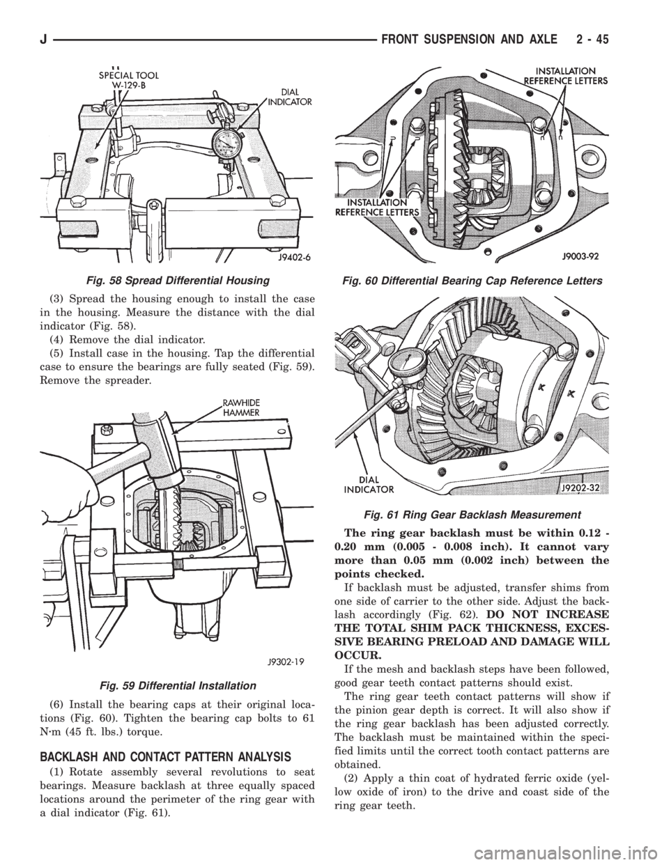
(3) Spread the housing enough to install the case
in the housing. Measure the distance with the dial
indicator (Fig. 58).
(4) Remove the dial indicator.
(5) Install case in the housing. Tap the differential
case to ensure the bearings are fully seated (Fig. 59).
Remove the spreader.
(6) Install the bearing caps at their original loca-
tions (Fig. 60). Tighten the bearing cap bolts to 61
Nzm (45 ft. lbs.) torque.
BACKLASH AND CONTACT PATTERN ANALYSIS
(1) Rotate assembly several revolutions to seat
bearings. Measure backlash at three equally spaced
locations around the perimeter of the ring gear with
a dial indicator (Fig. 61).The ring gear backlash must be within 0.12 -
0.20 mm (0.005 - 0.008 inch). It cannot vary
more than 0.05 mm (0.002 inch) between the
points checked.
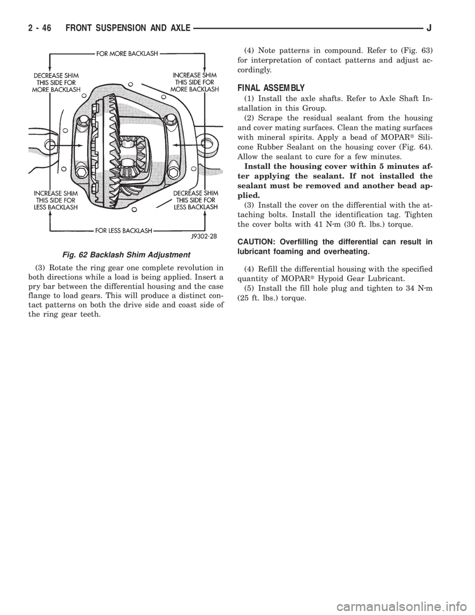
If backlash must be adjusted, transfer shims from
one side of carrier to the other side. Adjust the back-
lash accordingly (Fig. 62).DO NOT INCREASE
THE TOTAL SHIM PACK THICKNESS, EXCES-
SIVE BEARING PRELOAD AND DAMAGE WILL
OCCUR.
If the mesh and backlash steps have been followed,
good gear teeth contact patterns should exist.
The ring gear teeth contact patterns will show if
the pinion gear depth is correct. It will also show if
the ring gear backlash has been adjusted correctly.
The backlash must be maintained within the speci-
fied limits until the correct tooth contact patterns are
obtained.
(2) Apply a thin coat of hydrated ferric oxide (yel-
low oxide of iron) to the drive and coast side of the
ring gear teeth.
Fig. 58 Spread Differential Housing
Fig. 59 Differential Installation
Fig. 60 Differential Bearing Cap Reference Letters
Fig. 61 Ring Gear Backlash Measurement
JFRONT SUSPENSION AND AXLE 2 - 45
Page 81 of 2198
(3) Rotate the ring gear one complete revolution in
both directions while a load is being applied. Insert a
pry bar between the differential housing and the case
flange to load gears. This will produce a distinct con-
tact patterns on both the drive side and coast side of
the ring gear teeth.(4) Note patterns in compound. Refer to (Fig. 63)
for interpretation of contact patterns and adjust ac-
cordingly.
FINAL ASSEMBLY
(1) Install the axle shafts. Refer to Axle Shaft In-
stallation in this Group.
(2) Scrape the residual sealant from the housing
and cover mating surfaces. Clean the mating surfaces
with mineral spirits. Apply a bead of MOPARtSili-
cone Rubber Sealant on the housing cover (Fig. 64).
Allow the sealant to cure for a few minutes.
Install the housing cover within 5 minutes af-
ter applying the sealant. If not installed the
sealant must be removed and another bead ap-
plied.
(3) Install the cover on the differential with the at-
taching bolts. Install the identification tag. Tighten
the cover bolts with 41 Nzm (30 ft. lbs.) torque.
CAUTION: Overfilling the differential can result in
lubricant foaming and overheating.
(4) Refill the differential housing with the specified
quantity of MOPARtHypoid Gear Lubricant.
(5) Install the fill hole plug and tighten to 34 Nzm
(25 ft. lbs.) torque.
Fig. 62 Backlash Shim Adjustment
2 - 46 FRONT SUSPENSION AND AXLEJ
Page 84 of 2198
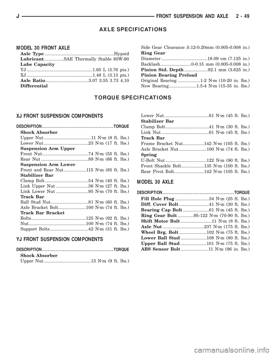
AXLE SPECIFICATIONS
MODEL 30 FRONT AXLE
Axle Type........................................................Hypoid
Lubricant................SAE Thermally Stable 80W-90
Lube Capacity
YJ .....................................................1.65 L (3.76 pts.)
XJ .....................................................1.48 L (3.13 pts.)
Axle Ratio...................................3.07 3.55 3.73 4.10
DifferentialSide Gear Clearance .0.12-0.20mm (0.005-0.008 in.)
Ring Gear
Diameter .....................................18.09 cm (7.125 in.)
Backlash.........................0-0.15 mm (0.005-0.008 in.)
Pinion Std. Depth...................92.1 mm (3.625 in.)
Pinion Bearing Preload
Original Bearing ..................1-2 Nzm (10-20 in. lbs.)
New Bearing ......................1.5-4 Nzm (15-35 in. lbs.)
TORQUE SPECIFICATIONS
XJ FRONT SUSPENSION COMPONENTS
DESCRIPTION ................................................TORQUE
Shock Absorber
Upper Nut ......................................11 Nzm (8 ft. lbs.)
Lower Nut ....................................23 Nzm (17 ft. lbs.)
Suspension Arm Upper
Front Nut .....................................74 Nzm (55 ft. lbs.)
Rear Nut ......................................89 Nzm (66 ft. lbs.)
Suspension Arm Lower
Front and Rear Nut ..................115 Nzm (85 ft. lbs.)
Stabilizer Bar
Clamp Bolt ...................................54 Nzm (40 ft. lbs.)
Link Upper Nut ..........................36 Nzm (27 ft. lbs.)
Link Lower Nut ..........................95 Nzm (70 ft. lbs.)
Track Bar
Ball Stud Nut ..............................81 Nzm (60 ft. lbs.)
Axle Bracket Bolt ......................100 Nzm (74 ft. lbs.)
Track Bar Bracket
Bolts............................................125 Nzm (92 ft. lbs.)
Nut ..............................................100 Nzm (74 ft. lbs.)
Support Bolts ...............................42 Nzm (31 ft. lbs.)
YJ FRONT SUSPENSION COMPONENTS
DESCRIPTION ................................................TORQUE
Shock Absorber
Upper Nut ......................................13 Nzm (9 ft. lbs.)Lower Nut ....................................61 Nzm (45 ft. lbs.)
Stabilizer Bar
Clamp Bolt ...................................41 Nzm (30 ft. lbs.)
Link Nut ......................................61 Nzm (45 ft. lbs.)
Track Bar
Frame Bracket Nut.................142 Nzm (105 ft. lbs.)
Axle Bracket Nut ......................100 Nzm (74 ft. lbs.)
Spring
U-Bolt Nut .................................122 Nzm (90 ft. lbs.)
Front Shackle Bolt ..................135 Nzm (100 ft. lbs.)
Rear Pivot Bolt........................142 Nzm (105 ft. lbs.)
MODEL 30 AXLE
DESCRIPTION ................................................TORQUE
Fill Hole Plug...........................34 Nzm (25 ft. lbs.)
Diff. Cover Bolt........................41 Nzm (30 ft. lbs.)
Bearing Cap Bolt.....................61 Nzm (45 ft. lbs.)
Ring Gear Bolt.............95-122 Nzm (70-90 ft. lbs.)
Shift Motor Bolt.........................11 Nzm (8 ft. lbs.)
Axle Nut.................................237 Nzm (175 ft. lbs.)
Wheel Brg. Bolt......................102 Nzm (75 ft. lbs.)
Lower Ball Stud.....................108 Nzm (80 ft. lbs.)
Upper Ball Stud.....................101 Nzm (75 ft. lbs.)
ABS Sensor Bolt......................11 Nzm (96 in. lbs.)
JFRONT SUSPENSION AND AXLE 2 - 49
Page 86 of 2198
REAR SUSPENSION AND AXLES
CONTENTS
page page
8 1/4 AXLE............................ 30
AXLE NOISE/VIBRATION DIAGNOSIS......... 9
AXLE SPECIFICATIONS................... 51
GENERAL INFORMATION.................. 1
MODEL 35 AXLE........................ 13TORQUE SPECIFICATIONS................ 51
TRAC-LOK DIFFERENTIAL................. 45
XJ SUSPENSION......................... 3
YJ SUSPENSION......................... 6
GENERAL INFORMATION
SUSPENSION COMPONENTS
The Jeep rear suspension is comprised of;
²Drive axle
²Leaf springs
²Dual-action shock absorbers
²Track bar (YJ vehicles)
²Stabilizer bar (XJ vehicles)
²Jounce bumpers
The rear suspension design uses semi-elliptic
multi-leaf springs and a solid drive axle. The forward
end of the springs are mounted to the frame rail
hangers through rubber bushings. The bushings iso-
late road noise as the springs move. The rearward
end of the springs are attached to the frame by the
use of shackles. Again the spring and shackles use
rubber bushings to isolate road noise. The shackles
allow the springs to change their length as the vehi-
cle moves over various road conditions. The spring
and axle travel is limited through the use of bumpers
mounted on frame.
All suspension components that use bushings
should be tightened with the vehicle at normal ride
height. If the springs are not at normal ride position,
vehicle ride comfort could be affected. Rubber bush-
ings must never be lubricated.
The springs are attached to the axle pads with U-
bolts and plates. The springs use a center bolt that
holds the spring leafs in position. The bolt is also
used to locate the spring assembly to the axle pad.
Ride control is accomplished through the use of du-
al-action shock absorbers. The shocks dampen the
jounce and rebound as the vehicle travels over vari-
ous road conditions. The top of shock absorbers are
bolted to the frame bracket. The bottom of the shocks
are bolted to the axle bracket.
The stabilizer bar on the XJ is used to minimize
vehicle rear sway during turns. The bar helps the ve-
hicle maintain a flat attitude to the road surface. The
bar extends across the underside of the chassis and
connects to the frame rails. The links are connectedto the axle brackets. All mounting points of the sta-
bilizer bar are isolated by bushings.
The track bar on the YJ is used to minimize rear
axle side-to-side movement. The track bar is attached
to the frame rail bracket and axle bracket and is iso-
lated with bushings.
The jounce bumpers are used to limit the jounce
and rebound travel of the suspension.
AXLES
The Model 35 axle is standard for XJ and YJ vehi-
cles. The 8 1/4 axle is available in XJ vehicles with-
out ABS brakes.
The Model 35 and 8 1/4 axle housings has a cast
iron center section. Two steel axle shaft tubes are
pressed into the differential housing and welded.
It is not necessary to remove the axle from the ve-
hicle for service. A removable differential cover is
provided for routine vehicle service. If the differential
housing is damaged, the complete axle assembly can
be removed.
For complete drive axle assembly removal and in-
stallation refer to Drive Axle Assembly Replacement
in this Group.
IDENTIFICATION
Model 35 axle has the assembly part number and
gear ratio listed on a tag. The tag is attached to the left
side of the housing cover (Fig. 1). Build date identifica-
tion codes on axles are stamped on the axle shaft tube
cover side. The Model 35 axle has a flat housing cover
gasket flange at the outer edge (Fig. 1).
The 8 1/4 axle has the build date code and gear ra-
tio tags attached to the housing cover (Fig. 2). The
housing cover gasket has a rolled gasket flange at
the outer edge (Fig. 2).
²The Model 35 axle has shaft tubes that are 2.625
inch (66.67 mm) in diameter.
²The 8 1/4 axle has axle shaft tubes that are 3.0-
inch (76.2 mm) in diameter.
JREAR SUSPENSION AND AXLES 3 - 1
Page 87 of 2198

STANDARD DIFFERENTIAL OPERATION
The differential gear system divides the torque be-
tween the axle shafts. It allows the axle shafts to ro-
tate at different speeds when turning corners.
Each differential side gear is splined to an axle
shaft. The pinion gears are mounted on a pinion
mate shaft and are free to rotate on the shaft. The
pinion gear is fitted in a bore in the differential case
and is positioned at a right angle to the axle shafts.
In operation, power flow occurs as follows:
²The pinion gear rotates the ring gear²The ring gear (bolted to the differential case) ro-
tates the case
²The differential pinion gears (mounted on the pin-
ion mate shaft in the case) rotate the side gears
²The side gears (splined to the axle shafts) rotate
the shafts
During straight-ahead driving, the differential pin-
ion gears do not rotate on the pinion mate shaft. This
occurs because input torque applied to the gears is
divided and distributed equally between the two side
gears. As a result, the pinion gears revolve with the
pinion mate shaft but do not rotate around it (Fig. 3).
When turning corners, the outside wheel must travel
a greater distance than the inside wheel in order to
complete a turn. The difference must be compensated
for, to prevent the tires from scuffing and skidding
through turns. To accomplish this, the differential al-
lows the axle shafts to turn at unequal speeds (Fig. 4).
In this instance, the input torque applied to the pinion
gears is not divided equally. The pinion gears now ro-
tate around the pinion mate shaft in opposite directions.
This allows the side gear and axle shaft attached to the
outside wheel to rotate at a faster speed.
Fig. 4 Differential OperationÐOn Turns
Fig. 1 Model 35 Differential Cover
Fig. 2 8 1/4 Differential Cover
Fig. 3 Differential OperationÐStraight-Ahead Driving
3 - 2 REAR SUSPENSION AND AXLESJ