fuse block JEEP CHEROKEE 1995 Service Manual PDF
[x] Cancel search | Manufacturer: JEEP, Model Year: 1995, Model line: CHEROKEE, Model: JEEP CHEROKEE 1995Pages: 2198, PDF Size: 82.83 MB
Page 691 of 2198

through this switch to circuit Q22. The Q22 circuit
then goes to the right rear window motor.
Ground for the window motor is supplied on the
Q12 circuit back to the right rear door switch. Circu-
ity internal to the switch then passes the ground to
circuit Q28. Circuit Q28 goes from the right rear door
switch to the master switch. A bus bar, internal to
the switch, connects the Q28 circuit to the Z1 circuit.
For window UP operation the circuits are reversed.
Circuits Q28 and Q12 are the feeds, and circuits Q22,
Q33 and Q18 are the grounds.
If the switch is being operated from the RIGHT
REAR door, and the operator is requesting window
DOWN operation, power is supplied on the Q1 circuit
from the driver's master switch circuit through the
switch to the Q22 circuit.
Ground for the motor is supplied on the Q12 circuit
through the switch and back to the master switch on
circuit Q28. A bus bar, internal to the switch, con-
nects the Q28 circuit to the Z1 circuit.
For window UP operation, the circuits are reversed.
Circuit Q12 is the power and circuit Q22 is the
ground.HELPFUL INFORMATION
²When the ignition switch is in the RUN position, it
connects circuit A1 from fuse 11 in the Power Distri-
bution Center (PDC) to circuit A38.
²Refer to the appropriate group of the Service Man-
ual for test procedures.
DIAGRAM INDEX
Component Page
Circuit Breaker (Fuse Block Cavity 6)............8W-60-3
Fuse 6 (PDC)...........................8W-60-3
Ignition Switch..........................8W-60-3
Power Window Door Switches................8W-60-4
Power Window Master Switch................8W-60-3
Power Window Motors.....................8W-60-4
8W - 60 - 2 8W-60 POWER WINDOWSÐXJ VEHICLESJ
Page 694 of 2198
POWER DOOR LOCKS
POWER DOOR LOCKS
Two relays provide power for the power door lock
motors. The Unlock relay provides power for the un-
lock circuits while the Lock relay powers the lock cir-
cuits. Either the power door lock switches or the
remote keyless entry module operate the Unlock and
Lock relays.
LOCK RELAY
Circuit M1 from fuse 9 in the fuse block powers cir-
cuit P38. When either power door lock switch is put
in the LOCK position, the switch connects circuit P38
to circuit P35. If the operator uses Remote Keyless
Entry (RKE), the RKE module powers circuit P35. In
either case, circuit P35 supplies power to the coil side
of the lock relay, causing the relay contacts to close.
Circuit Z1 provides ground for the coil side of the
lock relay.
When the lock relay contacts close, they connect
battery voltage from circuit P37 to circuit P2. Circuit
P2 then supplies battery voltage to the power door
lock motors to LOCK the doors.
When the power doors LOCK, ground for the mo-
tors is on circuit P34 through the normally closed
contacts in the door unlock relay to ground on circuit
Z1.
UNLOCK RELAY
Circuit M1 from fuse 9 in the fuse block powers cir-
cuit P38. When either power door lock switch is put
in the UNLOCK position, the switch connects circuit
P38 to circuit P36. If the operator uses Remote Key-
less Entry (RKE), the RKE module powers circuit
P36. In either case, circuit P36 supplies power to the
coil side of the unlock relay, causing the relay con-
tacts to close. Circuit Z1 provides ground for the coil
side of the unlock relay.
When the unlock relay contacts close, they connect
battery voltage from circuit P37 to circuit P34. Cir-
cuit P34 then supplies battery voltage to the power
door lock motors to UNLOCK the doors.
When the power doors UNLOCK, ground for the
motors is on circuit P2 through the normally closed
contacts in the door lock relay to ground on circuit
Z1.
REMOTE KEYLESS ENTRY MODULE
Circuit M1 from the ignition off draw (IOD) fuse in
cavity 9 of the fuse block supplies power to the Re-
mote Keyless Entry (RKE) module. Circuit F87 from
fuse 17 in the fuse block supplies power to the RKE
module when the ignition switch is in the START or
RUN position. Circuit Z1 provides ground for the
RKE module.
The RKE module UNLOCKS the doors by energiz-
ing the unlock relay on circuit P36. Refer to Unlock
Relay.
The module LOCKS the doors by energizing the
lock relay on circuit P35. Refer to Lock Relay.
HELPFUL INFORMATION
²Fuse 13 in the fuse block powers circuit P37. Cir-
cuit A7 from fuse 3 in the PDC feeds fuse 13 in the
fuse block.
²Circuit A7 from fuse 3 in the PDC also feeds fuse
16 in the PDC. PDC fuse 16 powers fuse 9 in the
fuse block. Fuse 9 protects the M1 circuit.
DIAGRAM INDEX
Component Page
Chime/Buzzer Module......................8W-61-5
Fuse 3 (PDC).........................8W-61-2, 6
Fuse 6 (PDC)...........................8W-61-5
Fuse 9 (Fuse Block).......................8W-61-2
Fuse 11 (Fuse Block)......................8W-61-2
Fuse 13 (Fuse Block)......................8W-61-2
Fuse 14 (Fuse Block)......................8W-61-2
Fuse 16 (PDC)........................8W-61-2, 6
Fuse 17 (Fuse Block)......................8W-61-5
Headlamp Delay Module....................8W-61-5
Ignition Switch..........................8W-61-5
Liftgate Lock Motor.......................8W-61-4
Power Door Lock Motors...................8W-61-4
Power Door Lock Relay....................8W-61-3
Power Door Lock Switches..................8W-61-2
Power Door Unlock Relay...................8W-61-3
Remote Keyless Entry (RKE) Module............8W-61-6
Telltale Connector........................8W-61-5
J8W-61 POWER DOOR LOCKSÐXJ VEHICLES 8W - 61 - 1
Page 700 of 2198
POWER MIRRORS
POWER MIRRORS
Four switches operates the left and right power
mirrors. One switch selects right or left mirror. Each
mirror has two motors; a LEFT/RIGHT motor and a
UP/DOWN motor. The motors switch polarity to al-
low mirror adjustment.
Circuit A7 from fuse 3 in the Power Distribution
Center (PDC) supplies battery voltage to fuse 16 in
the PDC. Fuse 16 in the PDC supplies voltage to the
Ignition Off Draw (IOD) fuse (fuse 9) in the fuse
block. Fuse 9 supplies power to circuit M1. Circuit
M1 connects to circuit P38. Circuit P38 powers the
power mirror switch. Circuit Z1 connects to the
power mirror switch and supplies ground for the
power mirror system.
RIGHT POWER MIRROR OPERATION
In the right position, the power mirror switch sup-
plies power to the right mirror LEFT/RIGHT motor
on circuit P79 when a rightward adjustment is made.
Circuit P77 provides the ground path the for right-
ward adjustments.
When the operator makes leftward adjustment, po-
larity reverses. For leftward adjustments, the switch
supplies battery voltage to the right mirror LEFT/
RIGHT motor on circuit P77. Circuit P79 supplies
ground for leftward adjustments.
During upward adjustments, the switch supplies
voltage to the right mirror UP/DOWN motor on cir-
cuit P79. Circuit P78 supplies ground during upward
adjustments.
For downward adjustments, the polarity is re-
versed, the switch powers the right mirror UP/
DOWN motor on circuit P78. Circuit P79 supplies the
ground path.
LEFT POWER MIRROR OPERATION
In the left position, the power mirror switch sup-
plies power to the left mirror LEFT/RIGHT motor on
circuit P79 when a rightward adjustment is made.
Circuit P81 provides the ground path the for right-
ward adjustments.
When the operator makes leftward adjustment, po-
larity reverses. For leftward adjustments, the switch
supplies battery voltage the left mirror LEFT/RIGHT
motor on circuit P81. Circuit P79 supplies ground for
leftward adjustments.
During upward adjustments, the switch supplies
voltage to the left mirror UP/DOWN motor on circuit
P79. Circuit P80 supplies ground during upward ad-
justments.
For downward adjustments, the polarity is re-
versed, the switch powers the left mirror UP/DOWN
motor on circuit P80. Circuit P79 supplies the ground
path.
HELPFUL INFORMATION
²Check fuse 9 in the fuse block
²Check fuses 3 and 16 in the PDC
DIAGRAM INDEX
Component Page
Fuse 3 (PDC)...........................8W-62-2
Fuse 9 (Fuse Block).......................8W-62-2
Fuse 16 (PDC)..........................8W-62-2
Power Mirrors..........................8W-62-2
Power Mirror Switch......................8W-62-2
J8W-62 POWER MIRRORSÐXJ VEHICLES 8W - 62 - 1
Page 702 of 2198

POWER SEAT
POWER SEAT
Battery voltage for the power seat system is sup-
plied by circuit A11, which is HOT at all times. This
circuit connects to the power accessory tap in the
fuse block and the power seat switch. The circuit
breaker in cavity 16 protects circuit A11.
A BUS bar internal to the power seat switch con-
nects the power from circuit A11 to the switches.
Grounding for the seat system is supplied on circuit
Z1.
The motors located under the seat are protected by
circuit breakers wired in with the motors. Each mo-
tor has its own circuit breaker.
When the operator selects the FRONT VERTICAL
UP function, power is passed on the A11 circuit
through the closed contacts in the switch to the S5
circuit. The S5 circuit connects to the motor. Ground
is provided on the S6 circuit back to the switch. A
ground BUS bar internal to the switch then connects
to the Z1 circuit.
For FRONT VERTICAL DOWN function the cir-
cuits are reversed. S6 is the feed and S5 is the
ground.
When the operator selects the SEAT FORWARD
function, power is passed on the A11 circuit through
the closed contacts in the switch to the S3 circuit.
The S3 circuit connects to the motor. Ground is pro-
vided on the S4 circuit back to the switch. A ground
BUS bar internal to the switch then connects to the
Z1 circuit.
For SEAT REARWARD function the circuits are re-
versed. S4 is the feed and S3 is the ground.
When the operator selects the REAR VERTICAL
UP function, power is passed on the A11 circuitthrough the closed contacts in the switch to the S1
circuit. The S1 circuit connects to the motor. Ground
is provided on the S2 circuit back to the switch. A
ground BUS bar internal to the switch then connects
to the Z1 circuit.
For REAR VERTICAL DOWN function the circuits
are reversed. S2 is the feed and S1 is the ground.
When the operator selects the SEAT UP function
power is passed on the A11 circuit through the closed
contacts in the switch to the S1 and S5 circuits. The
S1 circuit connects to the rear UP/DOWN motor, and
S5 connects to the front UP/DOWN motor. Ground is
provided on the S2 and S6 circuits back to the
switch. A ground BUS bar internal to the switch then
connects to the Z1 circuit.
For SEAT DOWN function the circuits are re-
versed. S2 and S6 circuits are the feeds and S1 and
S5 are the grounds.
HELPFUL INFORMATION
²Check the 30 amp circuit breaker in cavity 16 of
the fuse block.
DIAGRAM INDEX
Component Page
Circuit Breaker (Fuse Block Cavity 16)...........8W-63-2
Fuse 3 (Fuse Block).......................8W-63-2
Power Seat............................8W-63-2
Power Seat Switch.......................8W-63-2
J8W-63 POWER SEATÐXJ VEHICLES 8W - 63 - 1
Page 814 of 2198
WIRING DIAGRAMS
CONTENTS
page page
8W-01 GENERAL INFORMATIONÐWIRING
DIAGRAMS...................... 8W-01-1
8W-10 FUSE/FUSE BLOCK........... 8W-10-1
8W-11 POWER DISTRIBUTION........ 8W-11-1
8W-15 GROUND DISTRIBUTION....... 8W-15-1
8W-20 CHARGING SYSTEM.......... 8W-20-1
8W-21 STARTING SYSTEM........... 8W-21-1
8W-30 FUEL/IGNITION.............. 8W-30-1
8W-31 TRANSMISSION CONTROLS.... 8W-31-1
8W-32 ANTI-LOCK BRAKES........... 8W-32-1
8W-33 VEHICLE SPEED CONTROL..... 8W-33-1
8W-40 INSTRUMENT CLUSTER....... 8W-40-1
8W-41 HORN/CIGAR LIGHTER........ 8W-41-1
8W-42 AIR CONDITIONING/HEATER.... 8W-42-1
8W-44 INTERIOR LIGHTING.......... 8W-44-1
8W-47 AUDIO SYSTEM.............. 8W-47-18W-48 HEATED REAR WINDOW....... 8W-48-1
8W-49 OVERHEAD CONSOLE.......... 8W-49-1
8W-50 FRONT LIGHTING............ 8W-50-1
8W-51 REAR LIGHTING............. 8W-51-1
8W-52 TURN SIGNALS.............. 8W-52-1
8W-53 WIPERS.................... 8W-53-1
8W-54 TRAILER TOW................ 8W-54-1
8W-60 POWER WINDOWS............ 8W-60-1
8W-61 POWER DOOR LOCKS......... 8W-61-1
8W-62 POWER MIRRORS............ 8W-62-1
8W-63 POWER SEAT................ 8W-63-1
8W-70 SPLICE INFORMATION........ 8W-70-1
8W-80 CONNECTOR PIN OUTS....... 8W-80-1
8W-90 CONNECTOR LOCATIONS...... 8W-90-1
8W-95 SPLICE LOCATIONS........... 8W-95-1
HOW TO USE THIS GROUP
The purpose of this group is to show the electrical
circuits in a clear, simple fashion and to make trou-
bleshooting easier. Components that work together
are shown together. All electrical components used in
a specific system are shown on one diagram. The feed
for a system is shown at the top of the page. All
wires, connectors, splices, and components are shown
in the flow of current to the bottom of the page. Wir-
ing which is not part of the circuit represented is ref-
erenced to another page/section, where the complete
circuit is shown. In addition, all switches, compo-
nents, and modules are shown in theat rest posi-
tion with the doors closed and the key removed
from the ignition.
If a component is part of several different circuits,
it is shown in the diagram for each. For example, the
headlamp switch is the main part of the exterior
lighting, but it also affects the interior lighting and
the chime warning system.
It is important to realize that no attempt is
made on the diagrams to represent components
and wiring as they appear on the vehicle. For
example, a short piece of wire is treated the
same as a long one. In addition, switches and
other components are shown as simply as pos-
sible, with regard to function only.
The wiring diagram show circuits for all wheel-
bases. If there is a difference in systems or compo-
nents between wheel-bases, an identifier is placed
next to the component.
SECTION IDENTIFICATION
Sections in Group 8W are organized by sub-sys-
tems. The sections contain circuit operation descrip-
tions, helpful information, and system diagrams. The
intention is to organize information by system, con-
sistently from year to year.
CONNECTOR LOCATIONS
Section 8W-90 contains Connector Location illus-
trations. The illustrations contain the connector
number and component identification. Connector Lo-
cation charts in Section 8W-90 reference the illustra-
tion number for components and connectors.
Section 8W-80 shows each connector and the cir-
cuits involved with that connector. The connectors
are identified using the number on the Diagram
pages.
SPLICE LOCATIONS
Splice Location charts in Section 8W-70 show the
entire splice, and provide references to other sections
the splice serves.
Section 8W-95 contains illustrations that show the
general location of the splices in each harness. The
illustrations show the splice by number, and provide
a written location.
JWIRING DIAGRAMSÐXJ-RHD 8W - 1 - 1
Page 816 of 2198
FUSE/FUSE BLOCK
GENERAL INFORMATION
This section covers the Fuse Block and all circuits
involved with it. For additional information on sys-
tem operation, refer to the appropriate section of the
wiring diagrams.
DIAGRAM INDEX
Component Page
ABS Control Module......................8W-10-4
Chime/Buzzer Module..................8W-10-5, 7, 8
Fuse Block...........................8W-10-2, 3
Fuse 1 (Fuse Block)......................8W-10-10
Fuse 3 (Fuse Block)......................8W-10-11
Fuse 3 (PDC)......................8W-10-6, 10, 12
Fuse 4 (Fuse Block)......................8W-10-11
Fuse 5 (Fuse Block).......................8W-10-7
Fuse 5 (PDC).........................8W-10-5, 8
Fuse 6 (Fuse Block).......................8W-10-7
Fuse 6 (PDC)......................8W-10-4, 6, 11
Fuse 7 (Fuse Block)......................8W-10-12
Fuse 7 (PDC)...........................8W-10-8
Fuse 8 (Fuse Block)......................8W-10-12
Fuse 9 (Fuse Block).......................8W-10-5
Fuse 10 (Fuse Block)......................8W-10-5
Fuse 11 (PDC)..........................8W-10-6
Fuse 12 (Fuse Block)......................8W-10-4
Fuse 12 (PDC)..........................8W-10-6
Fuse 13 (Fuse Block)......................8W-10-4
Fuse 14 (Fuse Block)......................8W-10-4
Fuse 18 (Fuse Block)......................8W-10-4
Fuse 19 (Fuse Block)......................8W-10-4
Fuse 20 (Fuse Block).....................8W-10-11
Fuse 26 (Fuse Block)......................8W-10-7
Headlamp Delay Relay.....................8W-10-5
Headlamp Switch.......................8W-10-5, 8
Headlamp Delay Module....................8W-10-7
Heated Rear Window......................8W-10-8
Ignition Switch......................8W-10-4, 6, 11
In-Line Circuit Breaker (Stop Lamp Relay)........8W-10-10
Instrument Cluster......................8W-10-7, 9
Overhead Console......................8W-10-5, 7
Powertrain Control Module..................8W-10-6
J8W-10 FUSE/FUSE BLOCKÐXJ-RHD 8W - 10 - 1
Page 828 of 2198
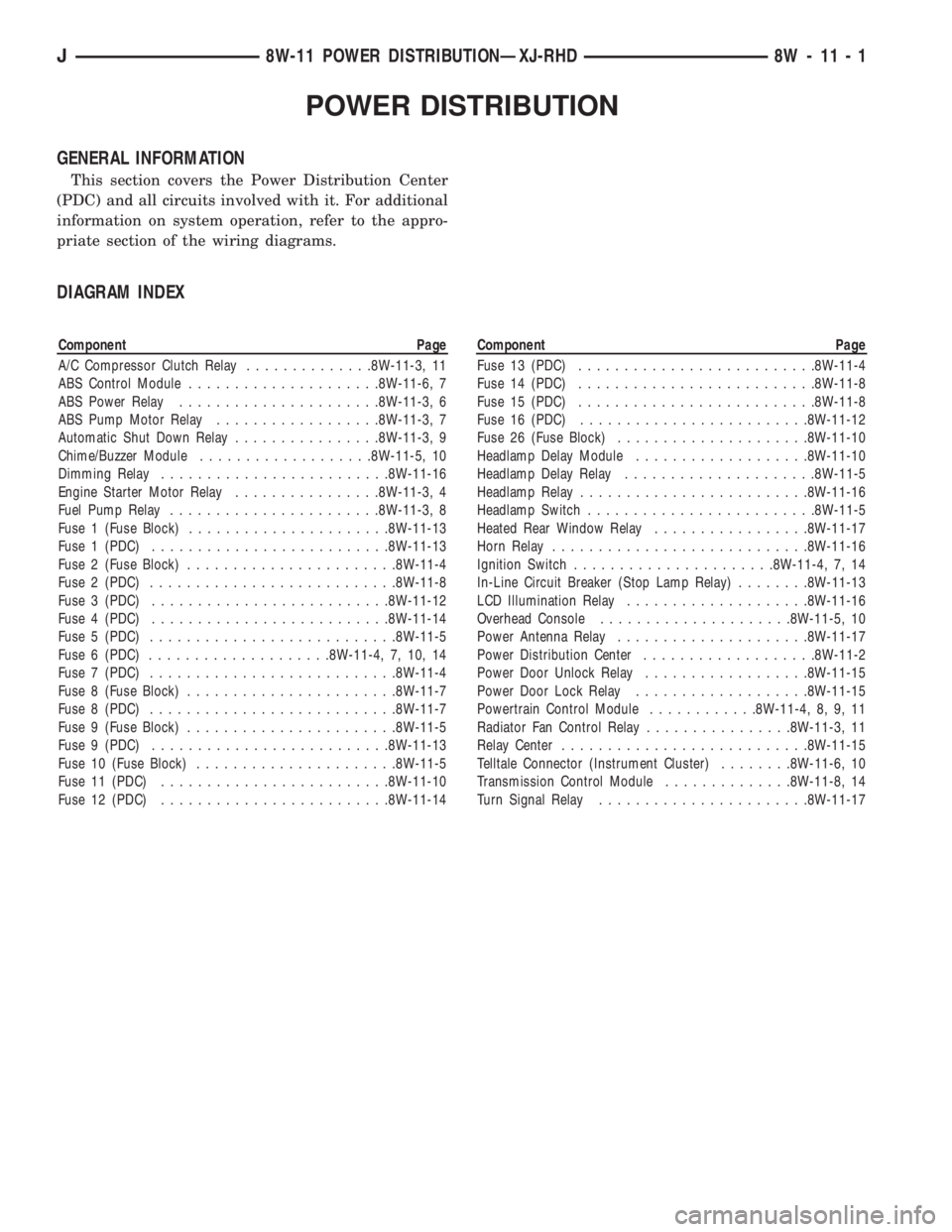
POWER DISTRIBUTION
GENERAL INFORMATION
This section covers the Power Distribution Center
(PDC) and all circuits involved with it. For additional
information on system operation, refer to the appro-
priate section of the wiring diagrams.
DIAGRAM INDEX
Component Page
A/C Compressor Clutch Relay..............8W-11-3, 11
ABS Control Module.....................8W-11-6, 7
ABS Power Relay......................8W-11-3, 6
ABS Pump Motor Relay..................8W-11-3, 7
Automatic Shut Down Relay................8W-11-3, 9
Chime/Buzzer Module...................8W-11-5, 10
Dimming Relay.........................8W-11-16
Engine Starter Motor Relay................8W-11-3, 4
Fuel Pump Relay.......................8W-11-3, 8
Fuse 1 (Fuse Block)......................8W-11-13
Fuse 1 (PDC)..........................8W-11-13
Fuse 2 (Fuse Block).......................8W-11-4
Fuse 2 (PDC)...........................8W-11-8
Fuse 3 (PDC)..........................8W-11-12
Fuse 4 (PDC)..........................8W-11-14
Fuse 5 (PDC)...........................8W-11-5
Fuse 6 (PDC)....................8W-11-4, 7, 10, 14
Fuse 7 (PDC)...........................8W-11-4
Fuse 8 (Fuse Block).......................8W-11-7
Fuse 8 (PDC)...........................8W-11-7
Fuse 9 (Fuse Block).......................8W-11-5
Fuse 9 (PDC)..........................8W-11-13
Fuse 10 (Fuse Block)......................8W-11-5
Fuse 11 (PDC).........................8W-11-10
Fuse 12 (PDC).........................8W-11-14Component Page
Fuse 13 (PDC)..........................8W-11-4
Fuse 14 (PDC)..........................8W-11-8
Fuse 15 (PDC)..........................8W-11-8
Fuse 16 (PDC).........................8W-11-12
Fuse 26 (Fuse Block).....................8W-11-10
Headlamp Delay Module...................8W-11-10
Headlamp Delay Relay.....................8W-11-5
Headlamp Relay.........................8W-11-16
Headlamp Switch.........................8W-11-5
Heated Rear Window Relay.................8W-11-17
Horn Relay............................8W-11-16
Ignition Switch......................8W-11-4, 7, 14
In-Line Circuit Breaker (Stop Lamp Relay)........8W-11-13
LCD Illumination Relay....................8W-11-16
Overhead Console.....................8W-11-5, 10
Power Antenna Relay.....................8W-11-17
Power Distribution Center...................8W-11-2
Power Door Unlock Relay..................8W-11-15
Power Door Lock Relay...................8W-11-15
Powertrain Control Module............8W-11-4, 8, 9, 11
Radiator Fan Control Relay................8W-11-3, 11
Relay Center...........................8W-11-15
Telltale Connector (Instrument Cluster)........8W-11-6, 10
Transmission Control Module..............8W-11-8, 14
Turn Signal Relay.......................8W-11-17
J8W-11 POWER DISTRIBUTIONÐXJ-RHD 8W - 11 - 1
Page 856 of 2198

FUEL/IGNITION
INDEX
page page
Automatic Shut Down (ASD) Relay............. 1
Battery Feed.............................. 1
Brake Switch Input......................... 5
Camshaft Position Sensor.................... 3
Crankshaft Position Sensor................... 3
Data Link Connector........................ 4
Diagram Index............................ 5
Engine Coolant Temperature Sensor............ 3
Fuel Injectors............................. 1
Fuel Pump Module......................... 2
Fuel Pump Relay.......................... 2
Heated Oxygen Sensor...................... 3Idle Air Control (IAC) Motor................... 2
Ignition Coil.............................. 2
Ignition Feed............................. 1
Ignition Switch............................ 1
Intake Air Temperature Sensor................ 4
Malfunction Indicator Lamp (MIL)............... 4
Manifold Absolute Pressure Sensor............. 4
Park/Neutral Position Switch.................. 4
Power (Device) Ground...................... 5
Tachometer Signal......................... 4
Throttle Position Sensor..................... 4
Vehicle Speed Sensor....................... 2
IGNITION SWITCH
Circuit A1 from fuse 11 in the power distribution
center (PDC), supplies battery voltage to the ignition
switch. Depending upon position, the ignition switch
powers circuits A21, A38, A41, or A48.
START POSITION
In the START position, the ignition switch connects
circuit A1 to circuit A41. Circuit A41 connects to the
coil side of the starter motor relay.
Additionally in the START position, the case
grounded ignition switch provides ground for the
brake lamp switch and the warning lamps in the in-
strument cluster.
START OR RUN POSITION
In the START or RUN position, the ignition switch
connects circuit A1 to circuit A21. Circuit A21 splices
to power the coil side of the Automatic Shut Down
(ASD) relay and the fuel pump relay.
RUN (ONLY) POSITION
When the ignition switch is in the RUN position, it
connects circuit A1 to circuit A38. Circuit A38 feeds
circuit L39.
ACCESSORY OR RUN POSITIONS
In the ACCESSORY or RUN positions, the ignition
switch connects circuit A1 to circuit A48. Circuit A48
connects to a bus bar in the fuse block.
AUTOMATIC SHUT DOWN (ASD) RELAY
When the ignition switch is in either the START or
RUN positions, it connects circuit A1 from fuse 6 in
the Power Distribution Center (PDC) to circuit A21.
Circuit A21 supplies battery voltage to the coil side of
the Automatic Shut Down (ASD) relay. The Power-train Control Module (PCM) provides ground for the
relay on circuit K51. Circuit K51 connects to cavity
51 of the PCM.
When the PCM grounds the ASD relay, contacts in-
side the relay close and connect circuit A18 from fuse
14 in the PDC to circuit A142. Circuit A142 splices to
the generator field terminal, fuel injectors, and igni-
tion coil. Circuit A142 also connects to cavity 57 of
the PCM.
HELPFUL INFORMATION
²Along with supplying voltage to the coil side of the
ASD relay, circuit A21 also supplies voltage to the
coil side of the fuel pump relay.
²Circuit A21 also connects to cavity 9 of the PCM.
BATTERY FEED
Circuit A14 from fuse 2 in the power distribution
center supplies battery voltage to cavity 3 of the
Powertrain Control Module (PCM).
HELPFUL INFORMATION
Circuit A14 also supplies power to the contact sides
of the fuel pump relay and fuse F2 in the PDC. Fuse
F2 powers circuit A18 which supplies voltage to the
contact side of the automatic shut down relay.
IGNITION FEED
When the ignition switch is in either the START or
RUN positions, it connects circuit A1 from fuse 6 in
the Power Distribution Center (PDC) to circuit A21.
Circuit A21 also connects to cavity 9 of the PCM and
provides the ignition input.
FUEL INJECTORS
When the Automatic Shut Down (ASD) relay con-
tacts close, they connect circuits A18 and A142. Cir-
J8W-30 FUEL/IGNITIONÐXJ-RHD 8W - 30 - 1
Page 857 of 2198

cuit A142 supplies voltage to the fuel injectors. Each
injector has a separate ground circuit controlled by
the PCM.
Circuit K11 provides ground for injector number
one. The K11 circuit connects to cavity 16 of the
PCM.
Circuit K12 provides ground for injector number
two. The K12 circuit connects to cavity 15 of the
PCM.
Circuit K13 provides ground for injector number
three. The K13 circuit connects to cavity 14 of the
PCM.
Circuit K14 provides ground for injector number
four. The K14 circuit connects to cavity 13 of the
PCM.
Circuit K15 provides ground for injector number
five. The K15 circuit connects to cavity 38 of the
PCM.
Circuit K16 provides ground for injector number
six. The K16 circuit connects to cavity 58 of the
PCM.
HELPFUL INFORMATION
²Circuit A142 splices to supply voltage to the fuel
injectors, ignition coil, PCM, generator.
²For information about fuel injector operation, refer
to Group 14.
IGNITION COIL
When the Automatic Shut Down (ASD) relay con-
tacts close, they connect circuits A18 and A142. Cir-
cuit A142 splices to supply voltage to the ignition
coil. The PCM controls the ground path for the igni-
tion coil on circuit K19. Circuit K19 connects to cav-
ity 19 of the PCM.
HELPFUL INFORMATION
Circuit A142 splices to supply voltage to the fuel
injectors, ignition coil, PCM, and generator.
FUEL PUMP RELAY
When the ignition switch is in either the START or
RUN positions, it connects circuit A1 from fuse 6 in
the Power Distribution Center (PDC) to circuit A21.
Circuit A21 supplies battery voltage to the coil side of
the fuel pump relay. The Powertrain Control Module
(PCM) provides ground for the relay on circuit K51.
Circuit K51 connects to cavity 51 of the PCM.
When the PCM grounds the fuel pump relay, con-
tacts inside the relay close and connect circuit A14
from fuse 14 in the PDC to circuit A141. Circuit A141
connects to circuit A241. Circuit A241 supplies volt-
age to the fuel pump motor (part of the in-tank fuel
pump module).
HELPFUL INFORMATION
²Circuit A14 also splices to supply battery voltage
to cavity 3 of the PCM.²Circuit A141 also supplies battery voltage to the
heated oxygen sensor.
FUEL PUMP MODULE
FUEL PUMP MOTOR
When the fuel pump relay contacts close, the relay
supplies voltage to the fuel pump motor. Circuit A141
from the relay supplies voltage to circuit A241. Cir-
cuit A241 connects to circuit F9 in the fuel pump mo-
tor. Circuit Z1 provides ground for the fuel pump
motor.
FUEL LEVEL SENSOR
The fuel level sensor is a variable resistor. Circuit
G4 connects the fuel level sensor to the fuel gauge in
the instrument cluster. Circuit F87 from fuse 26 in
the fuse block supplies voltage to the fuel gauge. The
fuel level sensor draws voltage from circuit F87
through the fuel gauge on circuit G4. Circuit G4 con-
nects to the fuel level sensor.
Circuit Z1 provides the ground path for the fuel
level sensor.
HELPFUL INFORMATION
As current flows through the coils in the fuel
gauge, it creates a magnetic field. One of the coils in
the gauge receives fixed current. The other coil is
connected to the level sensor. The magnetic field con-
trols the position of the fuel gauge pointer.
The fuel level sensor contains a variable resistor.
As the position of the float arm on the fuel level sen-
sor changes, the resistor changes the current flow
through second coil in the fuel gauge. A change in
current flow alters the magnetic field in the fuel
gauge, which changes the pointer position.
IDLE AIR CONTROL (IAC) MOTOR
The Powertrain Control Module (PCM) operates
the idle air control motor through 4 circuits - K39,
K40, K59, and K60. Each circuit connects to separate
cavities in the PCM connector.
²Circuit K39 connects to cavity 39 of the PCM
²Circuit K40 connects to cavity 40 of the PCM
²Circuit K59 connects to cavity 59 of the PCM
²Circuit K60 connects to cavity 60 of the PCM
VEHICLE SPEED SENSOR
Circuit K7 supplies 8 volts from the Powertrain
Control Module (PCM) to the vehicle speed sensor.
The K7 circuit connects to cavity 7 of the PCM.
Circuit G7 from the vehicle speed sensor provides
an input signal to the PCM. The G7 circuit connects
to cavity 47 of the PCM.
The PCM provides a ground for the vehicle speed
sensor signal (circuit G7) through circuit K4. Circuit
K4 connects to cavity 4 of the PCM.
8W - 30 - 2 8W-30 FUEL/IGNITIONÐXJ-RHDJ
Page 872 of 2198
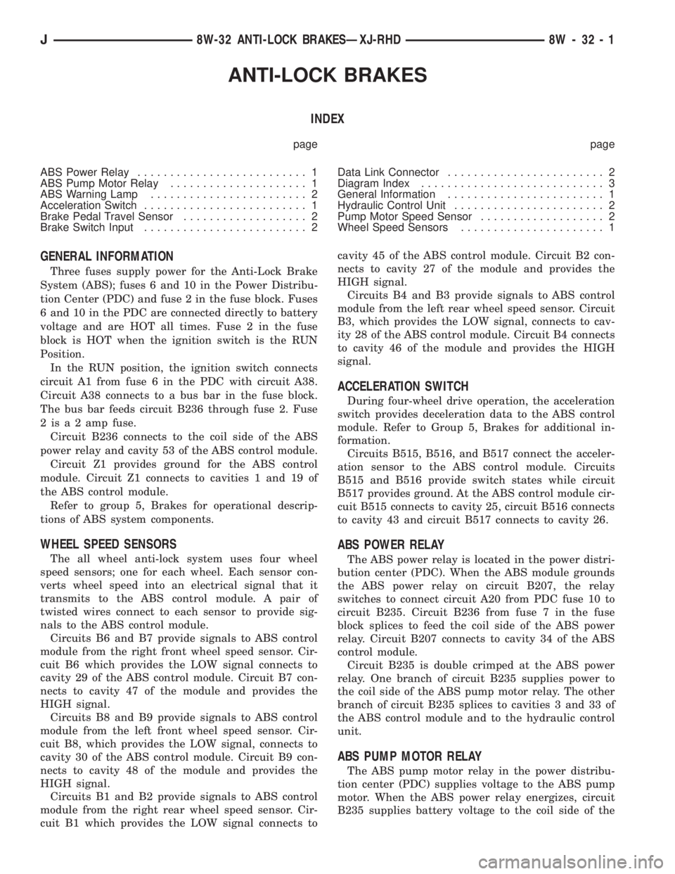
ANTI-LOCK BRAKES
INDEX
page page
ABS Power Relay.......................... 1
ABS Pump Motor Relay..................... 1
ABS Warning Lamp........................ 2
Acceleration Switch......................... 1
Brake Pedal Travel Sensor................... 2
Brake Switch Input......................... 2Data Link Connector........................ 2
Diagram Index............................ 3
General Information........................ 1
Hydraulic Control Unit....................... 2
Pump Motor Speed Sensor................... 2
Wheel Speed Sensors...................... 1
GENERAL INFORMATION
Three fuses supply power for the Anti-Lock Brake
System (ABS); fuses 6 and 10 in the Power Distribu-
tion Center (PDC) and fuse 2 in the fuse block. Fuses
6 and 10 in the PDC are connected directly to battery
voltage and are HOT all times. Fuse 2 in the fuse
block is HOT when the ignition switch is the RUN
Position.
In the RUN position, the ignition switch connects
circuit A1 from fuse 6 in the PDC with circuit A38.
Circuit A38 connects to a bus bar in the fuse block.
The bus bar feeds circuit B236 through fuse 2. Fuse
2 is a 2 amp fuse.
Circuit B236 connects to the coil side of the ABS
power relay and cavity 53 of the ABS control module.
Circuit Z1 provides ground for the ABS control
module. Circuit Z1 connects to cavities 1 and 19 of
the ABS control module.
Refer to group 5, Brakes for operational descrip-
tions of ABS system components.
WHEEL SPEED SENSORS
The all wheel anti-lock system uses four wheel
speed sensors; one for each wheel. Each sensor con-
verts wheel speed into an electrical signal that it
transmits to the ABS control module. A pair of
twisted wires connect to each sensor to provide sig-
nals to the ABS control module.
Circuits B6 and B7 provide signals to ABS control
module from the right front wheel speed sensor. Cir-
cuit B6 which provides the LOW signal connects to
cavity 29 of the ABS control module. Circuit B7 con-
nects to cavity 47 of the module and provides the
HIGH signal.
Circuits B8 and B9 provide signals to ABS control
module from the left front wheel speed sensor. Cir-
cuit B8, which provides the LOW signal, connects to
cavity 30 of the ABS control module. Circuit B9 con-
nects to cavity 48 of the module and provides the
HIGH signal.
Circuits B1 and B2 provide signals to ABS control
module from the right rear wheel speed sensor. Cir-
cuit B1 which provides the LOW signal connects tocavity 45 of the ABS control module. Circuit B2 con-
nects to cavity 27 of the module and provides the
HIGH signal.
Circuits B4 and B3 provide signals to ABS control
module from the left rear wheel speed sensor. Circuit
B3, which provides the LOW signal, connects to cav-
ity 28 of the ABS control module. Circuit B4 connects
to cavity 46 of the module and provides the HIGH
signal.
ACCELERATION SWITCH
During four-wheel drive operation, the acceleration
switch provides deceleration data to the ABS control
module. Refer to Group 5, Brakes for additional in-
formation.
Circuits B515, B516, and B517 connect the acceler-
ation sensor to the ABS control module. Circuits
B515 and B516 provide switch states while circuit
B517 provides ground. At the ABS control module cir-
cuit B515 connects to cavity 25, circuit B516 connects
to cavity 43 and circuit B517 connects to cavity 26.
ABS POWER RELAY
The ABS power relay is located in the power distri-
bution center (PDC). When the ABS module grounds
the ABS power relay on circuit B207, the relay
switches to connect circuit A20 from PDC fuse 10 to
circuit B235. Circuit B236 from fuse 7 in the fuse
block splices to feed the coil side of the ABS power
relay. Circuit B207 connects to cavity 34 of the ABS
control module.
Circuit B235 is double crimped at the ABS power
relay. One branch of circuit B235 supplies power to
the coil side of the ABS pump motor relay. The other
branch of circuit B235 splices to cavities 3 and 33 of
the ABS control module and to the hydraulic control
unit.
ABS PUMP MOTOR RELAY
The ABS pump motor relay in the power distribu-
tion center (PDC) supplies voltage to the ABS pump
motor. When the ABS power relay energizes, circuit
B235 supplies battery voltage to the coil side of the
J8W-32 ANTI-LOCK BRAKESÐXJ-RHD 8W - 32 - 1