center console JEEP CHEROKEE 1995 Service Repair Manual
[x] Cancel search | Manufacturer: JEEP, Model Year: 1995, Model line: CHEROKEE, Model: JEEP CHEROKEE 1995Pages: 2198, PDF Size: 82.83 MB
Page 148 of 2198
bubbles that are distributed throughout the hydrau-
lic system. This will make extra bleeding operations
necessary.
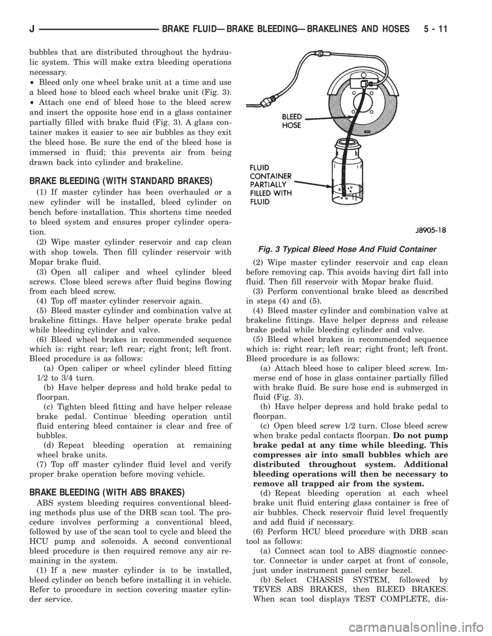
²Bleed only one wheel brake unit at a time and use
a bleed hose to bleed each wheel brake unit (Fig. 3).
²Attach one end of bleed hose to the bleed screw
and insert the opposite hose end in a glass container
partially filled with brake fluid (Fig. 3). A glass con-
tainer makes it easier to see air bubbles as they exit
the bleed hose. Be sure the end of the bleed hose is
immersed in fluid; this prevents air from being
drawn back into cylinder and brakeline.
BRAKE BLEEDING (WITH STANDARD BRAKES)
(1) If master cylinder has been overhauled or a
new cylinder will be installed, bleed cylinder on
bench before installation. This shortens time needed
to bleed system and ensures proper cylinder opera-
tion.
(2) Wipe master cylinder reservoir and cap clean
with shop towels. Then fill cylinder reservoir with
Mopar brake fluid.
(3) Open all caliper and wheel cylinder bleed
screws. Close bleed screws after fluid begins flowing
from each bleed screw.
(4) Top off master cylinder reservoir again.
(5) Bleed master cylinder and combination valve at
brakeline fittings. Have helper operate brake pedal
while bleeding cylinder and valve.
(6) Bleed wheel brakes in recommended sequence
which is: right rear; left rear; right front; left front.
Bleed procedure is as follows:
(a) Open caliper or wheel cylinder bleed fitting
1/2 to 3/4 turn.
(b) Have helper depress and hold brake pedal to
floorpan.
(c) Tighten bleed fitting and have helper release
brake pedal. Continue bleeding operation until
fluid entering bleed container is clear and free of
bubbles.
(d) Repeat bleeding operation at remaining
wheel brake units.
(7) Top off master cylinder fluid level and verify
proper brake operation before moving vehicle.
BRAKE BLEEDING (WITH ABS BRAKES)
ABS system bleeding requires conventional bleed-
ing methods plus use of the DRB scan tool. The pro-
cedure involves performing a conventional bleed,
followed by use of the scan tool to cycle and bleed the
HCU pump and solenoids. A second conventional
bleed procedure is then required remove any air re-
maining in the system.
(1) If a new master cylinder is to be installed,
bleed cylinder on bench before installing it in vehicle.
Refer to procedure in section covering master cylin-
der service.(2) Wipe master cylinder reservoir and cap clean
before removing cap. This avoids having dirt fall into
fluid. Then fill reservoir with Mopar brake fluid.
(3) Perform conventional brake bleed as described
in steps (4) and (5).
(4) Bleed master cylinder and combination valve at
brakeline fittings. Have helper depress and release
brake pedal while bleeding cylinder and valve.
(5) Bleed wheel brakes in recommended sequence
which is: right rear; left rear; right front; left front.
Bleed procedure is as follows:
(a) Attach bleed hose to caliper bleed screw. Im-
merse end of hose in glass container partially filled
with brake fluid. Be sure hose end is submerged in
fluid (Fig. 3).
(b) Have helper depress and hold brake pedal to
floorpan.
(c) Open bleed screw 1/2 turn. Close bleed screw
when brake pedal contacts floorpan.Do not pump
brake pedal at any time while bleeding. This
compresses air into small bubbles which are
distributed throughout system. Additional
bleeding operations will then be necessary to
remove all trapped air from the system.
(d) Repeat bleeding operation at each wheel
brake unit fluid entering glass container is free of
air bubbles. Check reservoir fluid level frequently
and add fluid if necessary.
(6) Perform HCU bleed procedure with DRB scan
tool as follows:
(a) Connect scan tool to ABS diagnostic connec-
tor. Connector is under carpet at front of console,
just under instrument panel center bezel.
(b) Select CHASSIS SYSTEM, followed by
TEVES ABS BRAKES, then BLEED BRAKES.
When scan tool displays TEST COMPLETE, dis-
Fig. 3 Typical Bleed Hose And Fluid Container
JBRAKE FLUIDÐBRAKE BLEEDINGÐBRAKELINES AND HOSES 5 - 11
Page 305 of 2198
DIAGNOSIS
COMPASS/DISPLAY SELF-DIAGNOSTIC TEST
This self-diagnostic test is used to determine that
the compass and all of its display segments are oper-
ating properly electrically. Initiate the self-diagnostic
test as follows:
(1) With the ignition switch in the OFF position,
simultaneously press and hold the COMP/TEMP but-
ton and the US/METRIC button.
(2) Turn ignition switch to the ON position.
(3) Continue to hold both buttons until the display
performs a walking segment test. In this test all of
the compass points are displayed, along with various
number combinations. These combinations verify that
all display segments are functional. If any segment
should fail to light during the test, the unit is faulty
and requires replacement. To repeat the test, momen-
tarily depress and release the COMP/TEMP button
one time.
(4) Momentarily depress and release the US/MET-
RIC button one time and all segments will light si-
multaneously for about 2 seconds. If any segment
should fail to light during the test, the unit is faulty
and requires replacement. To repeat the test, momen-
tarily depress and release the COMP/TEMP button
one time.
(5) Momentarily depress and release the US/MET-
RIC button one time or turn the ignition switch to
OFF to exit the self-diagnostic mode and return to
normal operation.
If the compass functions, but accuracy is sus-
pect, it may be necessary to perform a variation
adjustment. This procedure allows the unit to
accommodate variations in the earth's mag-
netic field strength based on geographic loca-
tion. See Compass Variation Adjustment, in this
group.
If the compass display has blanked out and
only CAL appears, demagnetizing may be nec-
essary to remove excessive residual magnetic
fields from the vehicle. See Compass Demagne-
tizing, in this group.
THERMOMETER DIAGNOSIS
The thermometer function is supported by a tem-
perature sensor, a wiring circuit and a portion of the
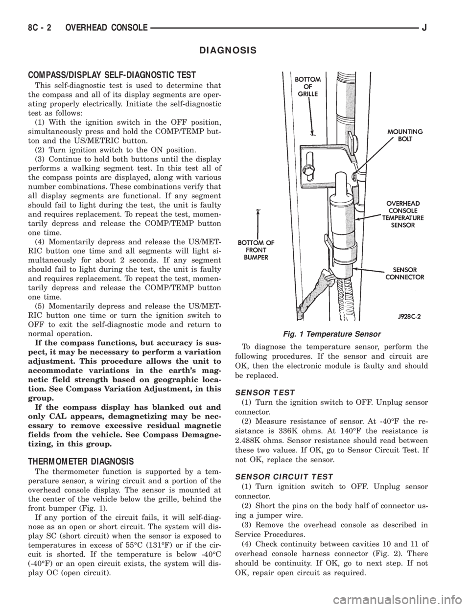
overhead console display. The sensor is mounted at
the center of the vehicle below the grille, behind the
front bumper (Fig. 1).
If any portion of the circuit fails, it will self-diag-
nose as an open or short circuit. The system will dis-
play SC (short circuit) when the sensor is exposed to
temperatures in excess of 55ÉC (131ÉF) or if the cir-
cuit is shorted. If the temperature is below -40ÉC
(-40ÉF) or an open circuit exists, the system will dis-
play OC (open circuit).To diagnose the temperature sensor, perform the
following procedures. If the sensor and circuit are
OK, then the electronic module is faulty and should
be replaced.
SENSOR TEST
(1) Turn the ignition switch to OFF. Unplug sensor
connector.
(2) Measure resistance of sensor. At -40ÉF the re-
sistance is 336K ohms. At 140ÉF the resistance is
2.488K ohms. Sensor resistance should read between
these two values. If OK, go to Sensor Circuit Test. If
not OK, replace the sensor.
SENSOR CIRCUIT TEST
(1) Turn ignition switch to OFF. Unplug sensor
connector.
(2) Short the pins on the body half of connector us-
ing a jumper wire.
(3) Remove the overhead console as described in
Service Procedures.
(4) Check continuity between cavities 10 and 11 of
overhead console harness connector (Fig. 2). There
should be continuity. If OK, go to next step. If not
OK, repair open circuit as required.
Fig. 1 Temperature Sensor
8C - 2 OVERHEAD CONSOLEJ
Page 309 of 2198
(4) With the degaussing tool still energized, slowly
back it away from the screw until the tool is at least
2 feet from the screw head, then unplug the tool.
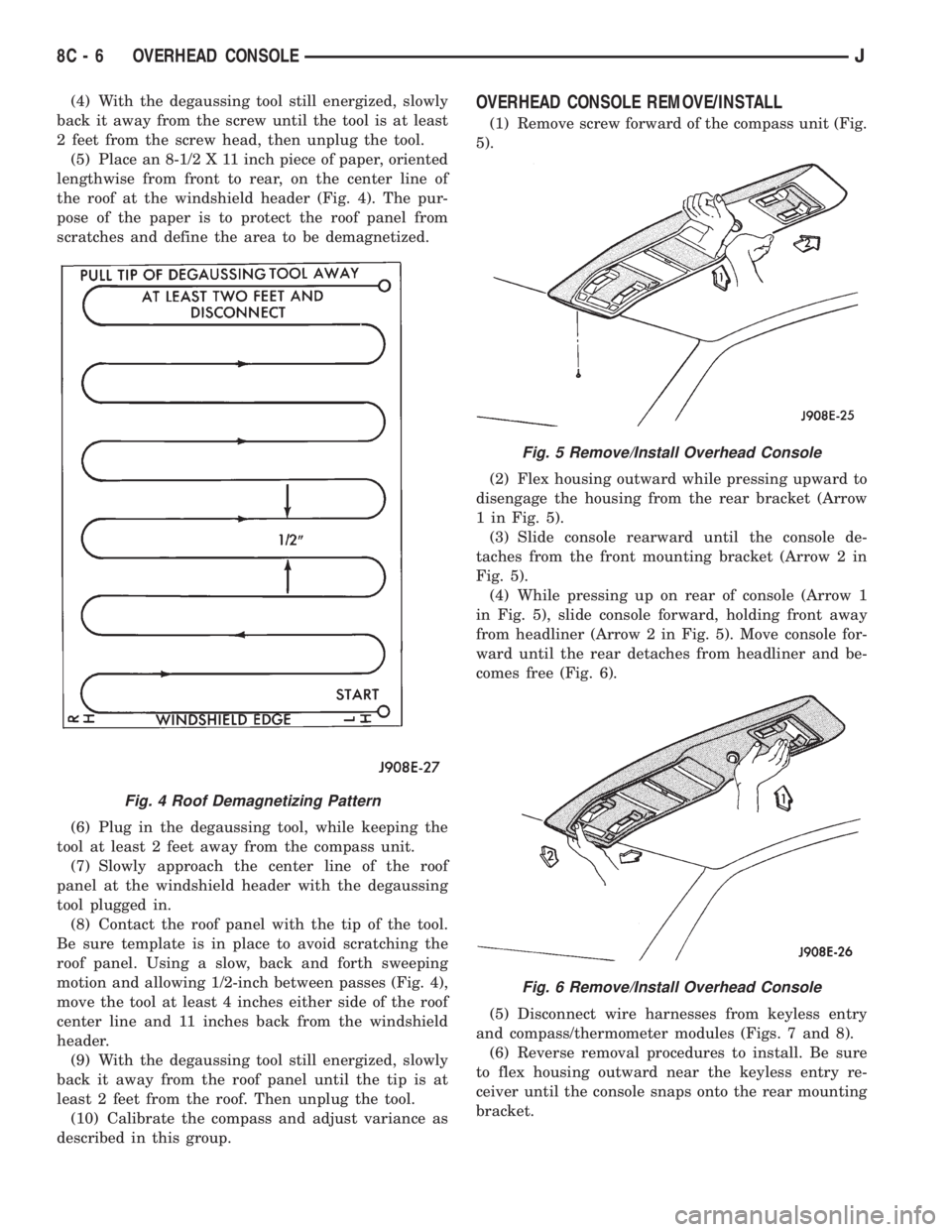
(5) Place an 8-1/2 X 11 inch piece of paper, oriented
lengthwise from front to rear, on the center line of
the roof at the windshield header (Fig. 4). The pur-
pose of the paper is to protect the roof panel from
scratches and define the area to be demagnetized.
(6) Plug in the degaussing tool, while keeping the
tool at least 2 feet away from the compass unit.
(7) Slowly approach the center line of the roof
panel at the windshield header with the degaussing
tool plugged in.
(8) Contact the roof panel with the tip of the tool.
Be sure template is in place to avoid scratching the
roof panel. Using a slow, back and forth sweeping
motion and allowing 1/2-inch between passes (Fig. 4),
move the tool at least 4 inches either side of the roof
center line and 11 inches back from the windshield
header.
(9) With the degaussing tool still energized, slowly
back it away from the roof panel until the tip is at
least 2 feet from the roof. Then unplug the tool.
(10) Calibrate the compass and adjust variance as
described in this group.OVERHEAD CONSOLE REMOVE/INSTALL
(1) Remove screw forward of the compass unit (Fig.
5).
(2) Flex housing outward while pressing upward to
disengage the housing from the rear bracket (Arrow
1 in Fig. 5).
(3) Slide console rearward until the console de-
taches from the front mounting bracket (Arrow 2 in
Fig. 5).
(4) While pressing up on rear of console (Arrow 1
in Fig. 5), slide console forward, holding front away
from headliner (Arrow 2 in Fig. 5). Move console for-
ward until the rear detaches from headliner and be-
comes free (Fig. 6).
(5) Disconnect wire harnesses from keyless entry
and compass/thermometer modules (Figs. 7 and 8).
(6) Reverse removal procedures to install. Be sure
to flex housing outward near the keyless entry re-
ceiver until the console snaps onto the rear mounting
bracket.
Fig. 4 Roof Demagnetizing Pattern
Fig. 5 Remove/Install Overhead Console
Fig. 6 Remove/Install Overhead Console
8C - 6 OVERHEAD CONSOLEJ
Page 310 of 2198
SUNGLASSES STORAGE BIN REMOVE/INSTALL
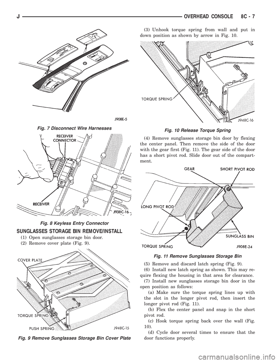
(1) Open sunglasses storage bin door.
(2) Remove cover plate (Fig. 9).(3) Unhook torque spring from wall and put in
down position as shown by arrow in Fig. 10.
(4) Remove sunglasses storage bin door by flexing
the center panel. Then remove the side of the door
with the gear first (Fig. 11). The gear side of the door
has a short pivot rod. Slide door out of the compart-
ment.
(5) Remove and discard latch spring (Fig. 9).
(6) Install new latch spring as shown. This may re-
quire flexing the housing in that area for clearance.
(7) Install new sunglasses storage bin door in the
open position as follows:
(a) Make sure the torque spring lines up with
the slot in the longer pivot rod, then insert the
longer pivot rod (Fig. 11).
(b) Flex the center panel and snap in the short
pivot rod.
(c) Hook torque spring back over the wall (Fig.
10).
(d) Cycle door several times to ensure that the
door functions properly.
Fig. 7 Disconnect Wire Harnesses
Fig. 8 Keyless Entry Connector
Fig. 9 Remove Sunglasses Storage Bin Cover Plate
Fig. 10 Release Torque Spring
Fig. 11 Remove Sunglasses Storage Bin
JOVERHEAD CONSOLE 8C - 7
Page 465 of 2198
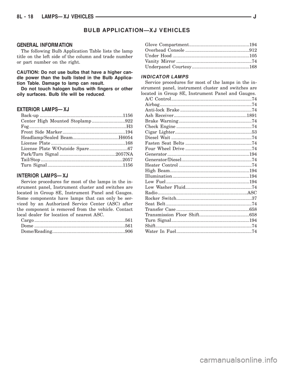
BULB APPLICATIONÐXJ VEHICLES
GENERAL INFORMATION
The following Bulb Application Table lists the lamp
title on the left side of the column and trade number
or part number on the right.
CAUTION: Do not use bulbs that have a higher can-
dle power than the bulb listed in the Bulb Applica-
tion Table. Damage to lamp can result.
Do not touch halogen bulbs with fingers or other
oily surfaces. Bulb life will be reduced.
EXTERIOR LAMPSÐXJ
Back-up .................................................................1156
Center High Mounted Stoplamp ..........................922
Fog ............................................................................H3
Front Side Marker .................................................194
Headlamp/Sealed Beam....................................H6054
License Plate ..........................................................168
License Plate W/Outside Spare ..............................67
Park/Turn Signal ............................................2057NA
Tail/Stop ................................................................2057
Turn Signal ...........................................................1156
INTERIOR LAMPSÐXJ
Service procedures for most of the lamps in the in-
strument panel, Instrument cluster and switches are
located in Group 8E, Instrument Panel and Gauges.
Some components have lamps that can only be ser-
viced by an Authorized Service Center (ASC) after
the component is removed from the vehicle. Contact
local dealer for location of nearest ASC.
Cargo .......................................................................561
Dome .......................................................................561
Dome/Reading.........................................................906Glove Compartment ...............................................194
Overhead Console ..................................................912
Under Hood ............................................................105
Vanity Mirror ...........................................................74
Underpanel Courtesy.............................................168
INDICATOR LAMPS
Service procedures for most of the lamps in the in-
strument panel, instrument cluster and switches are
located in Group 8E, Instrument Panel and Gauges.
A/C Control ...............................................................74
Airbag ........................................................................74
Anti-lock Brake ........................................................74
Ash Receiver .........................................................1891
Brake Warning .........................................................74
Check Engine ...........................................................74
Cigar Lighter ............................................................53
Diesel Wait ...............................................................74
Fasten Seat Belts ....................................................74
Four Wheel Drive ....................................................74
Generator ................................................................194
Generator/Diesel.......................................................74
Heater Control .........................................................74
High Beam..............................................................194
Illumination ............................................................194
Low Fuel .................................................................194
Low Washer Fluid....................................................74
Radio ......................................................................ASC
Rocker Switch...........................................................37
Seat Belt ...................................................................74
Transfer Case .........................................................658
Transmission Floor Shift.......................................658
Turn Signal.............................................................194
Shift ...........................................................................74
Water In Fuel ...........................................................74
8L - 18 LAMPSÐXJ VEHICLESJ
Page 488 of 2198
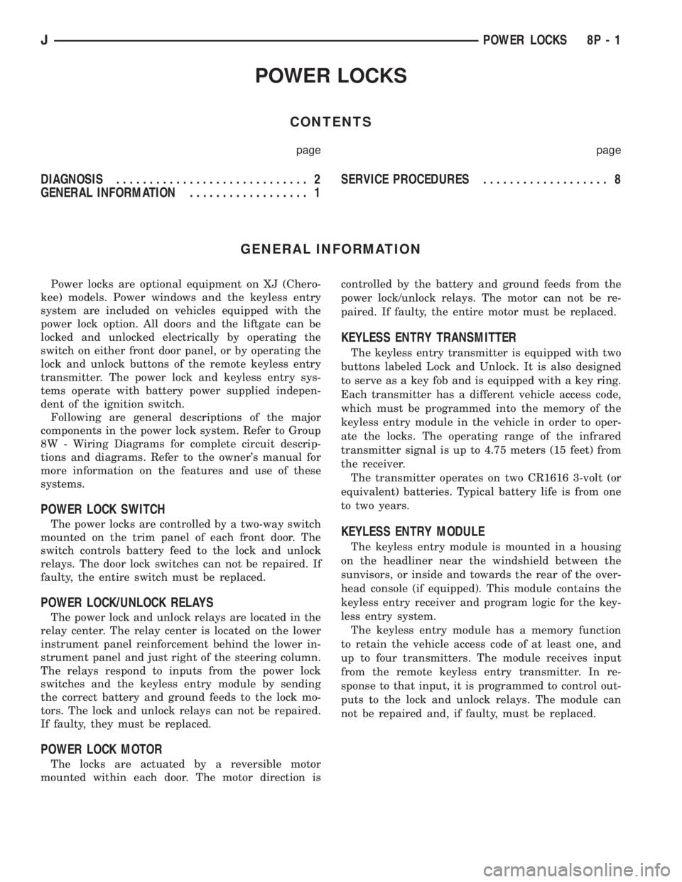
POWER LOCKS
CONTENTS
page page
DIAGNOSIS............................. 2
GENERAL INFORMATION.................. 1SERVICE PROCEDURES................... 8
GENERAL INFORMATION
Power locks are optional equipment on XJ (Chero-
kee) models. Power windows and the keyless entry
system are included on vehicles equipped with the
power lock option. All doors and the liftgate can be
locked and unlocked electrically by operating the
switch on either front door panel, or by operating the
lock and unlock buttons of the remote keyless entry
transmitter. The power lock and keyless entry sys-
tems operate with battery power supplied indepen-
dent of the ignition switch.
Following are general descriptions of the major
components in the power lock system. Refer to Group
8W - Wiring Diagrams for complete circuit descrip-
tions and diagrams. Refer to the owner's manual for
more information on the features and use of these
systems.
POWER LOCK SWITCH
The power locks are controlled by a two-way switch
mounted on the trim panel of each front door. The
switch controls battery feed to the lock and unlock
relays. The door lock switches can not be repaired. If
faulty, the entire switch must be replaced.
POWER LOCK/UNLOCK RELAYS
The power lock and unlock relays are located in the
relay center. The relay center is located on the lower
instrument panel reinforcement behind the lower in-
strument panel and just right of the steering column.
The relays respond to inputs from the power lock
switches and the keyless entry module by sending
the correct battery and ground feeds to the lock mo-
tors. The lock and unlock relays can not be repaired.
If faulty, they must be replaced.
POWER LOCK MOTOR
The locks are actuated by a reversible motor
mounted within each door. The motor direction iscontrolled by the battery and ground feeds from the
power lock/unlock relays. The motor can not be re-
paired. If faulty, the entire motor must be replaced.
KEYLESS ENTRY TRANSMITTER
The keyless entry transmitter is equipped with two
buttons labeled Lock and Unlock. It is also designed
to serve as a key fob and is equipped with a key ring.
Each transmitter has a different vehicle access code,
which must be programmed into the memory of the
keyless entry module in the vehicle in order to oper-
ate the locks. The operating range of the infrared
transmitter signal is up to 4.75 meters (15 feet) from
the receiver.
The transmitter operates on two CR1616 3-volt (or
equivalent) batteries. Typical battery life is from one
to two years.
KEYLESS ENTRY MODULE
The keyless entry module is mounted in a housing
on the headliner near the windshield between the
sunvisors, or inside and towards the rear of the over-
head console (if equipped). This module contains the
keyless entry receiver and program logic for the key-
less entry system.
The keyless entry module has a memory function
to retain the vehicle access code of at least one, and
up to four transmitters. The module receives input
from the remote keyless entry transmitter. In re-
sponse to that input, it is programmed to control out-
puts to the lock and unlock relays. The module can
not be repaired and, if faulty, must be replaced.
JPOWER LOCKS 8P - 1
Page 499 of 2198
(8) Reverse removal procedures to install. Be sure
to flex housing outward near the keyless entry mod-
ule until the console snaps onto the rear mounting
bracket.
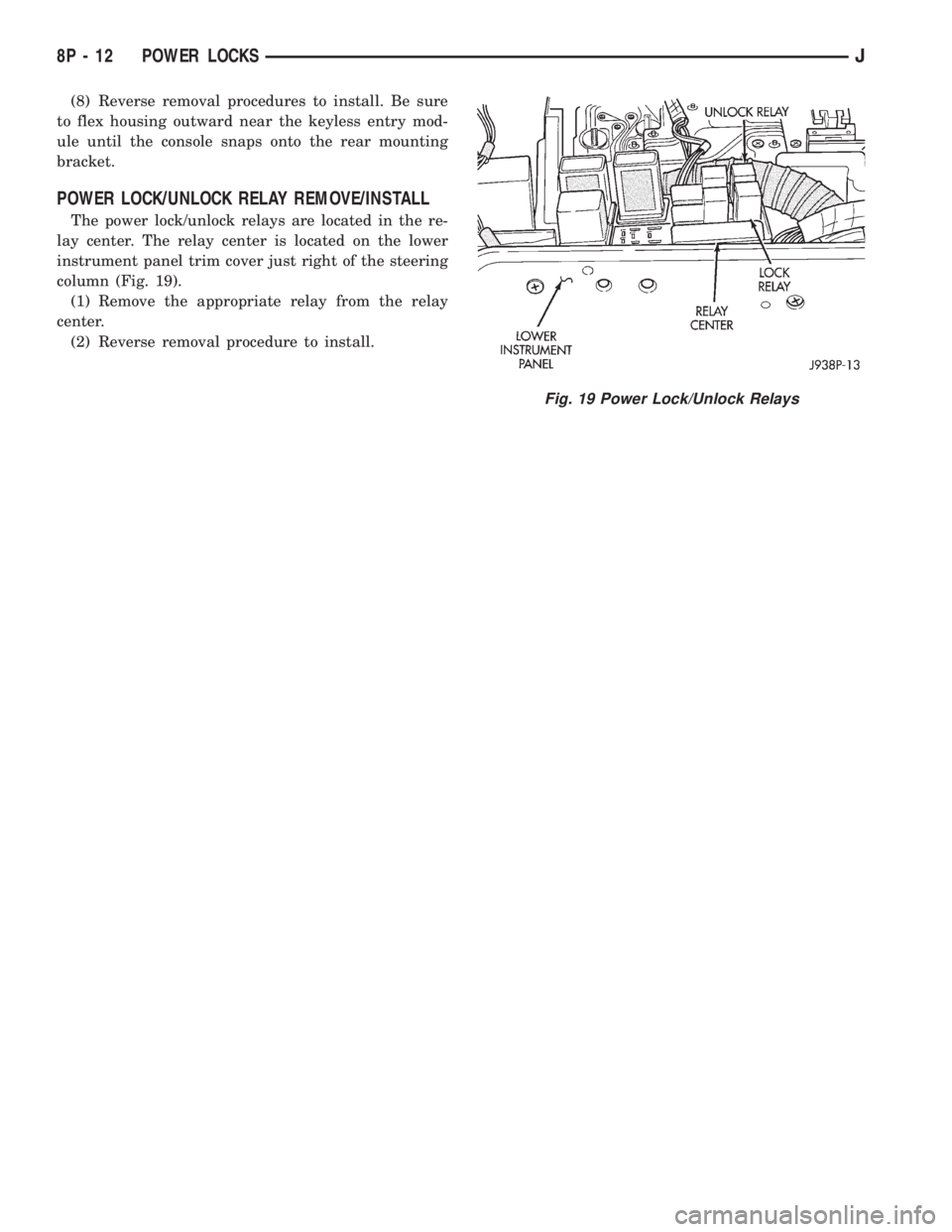
POWER LOCK/UNLOCK RELAY REMOVE/INSTALL
The power lock/unlock relays are located in the re-
lay center. The relay center is located on the lower
instrument panel trim cover just right of the steering
column (Fig. 19).
(1) Remove the appropriate relay from the relay
center.
(2) Reverse removal procedure to install.
Fig. 19 Power Lock/Unlock Relays
8P - 12 POWER LOCKSJ
Page 512 of 2198
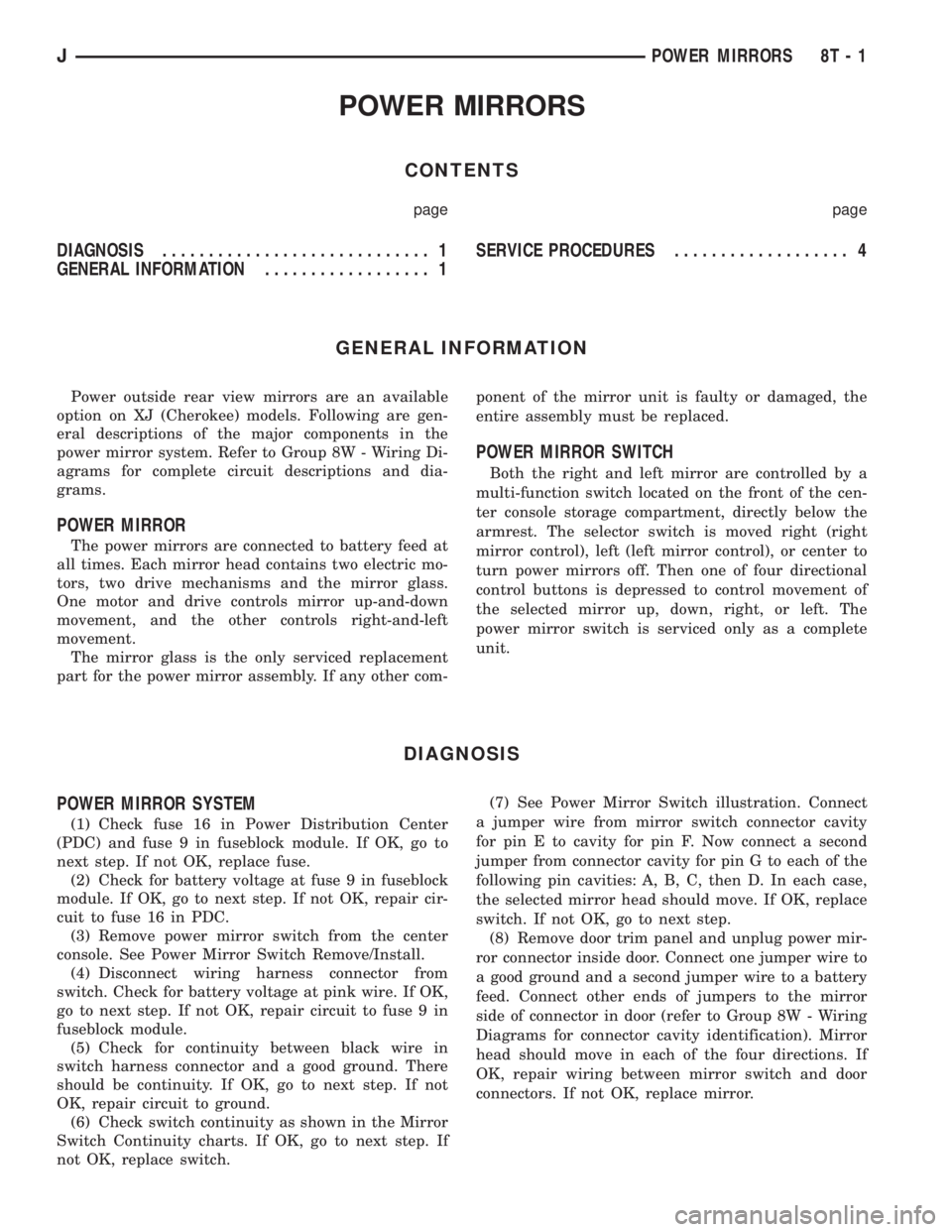
POWER MIRRORS
CONTENTS
page page
DIAGNOSIS............................. 1
GENERAL INFORMATION.................. 1SERVICE PROCEDURES................... 4
GENERAL INFORMATION
Power outside rear view mirrors are an available
option on XJ (Cherokee) models. Following are gen-
eral descriptions of the major components in the
power mirror system. Refer to Group 8W - Wiring Di-
agrams for complete circuit descriptions and dia-
grams.
POWER MIRROR
The power mirrors are connected to battery feed at
all times. Each mirror head contains two electric mo-
tors, two drive mechanisms and the mirror glass.
One motor and drive controls mirror up-and-down
movement, and the other controls right-and-left
movement.
The mirror glass is the only serviced replacement
part for the power mirror assembly. If any other com-ponent of the mirror unit is faulty or damaged, the
entire assembly must be replaced.
POWER MIRROR SWITCH
Both the right and left mirror are controlled by a
multi-function switch located on the front of the cen-
ter console storage compartment, directly below the
armrest. The selector switch is moved right (right
mirror control), left (left mirror control), or center to
turn power mirrors off. Then one of four directional
control buttons is depressed to control movement of
the selected mirror up, down, right, or left. The
power mirror switch is serviced only as a complete
unit.
DIAGNOSIS
POWER MIRROR SYSTEM
(1) Check fuse 16 in Power Distribution Center
(PDC) and fuse 9 in fuseblock module. If OK, go to
next step. If not OK, replace fuse.
(2) Check for battery voltage at fuse 9 in fuseblock
module. If OK, go to next step. If not OK, repair cir-
cuit to fuse 16 in PDC.
(3) Remove power mirror switch from the center
console. See Power Mirror Switch Remove/Install.
(4) Disconnect wiring harness connector from
switch. Check for battery voltage at pink wire. If OK,
go to next step. If not OK, repair circuit to fuse 9 in
fuseblock module.
(5) Check for continuity between black wire in
switch harness connector and a good ground. There
should be continuity. If OK, go to next step. If not
OK, repair circuit to ground.
(6) Check switch continuity as shown in the Mirror
Switch Continuity charts. If OK, go to next step. If
not OK, replace switch.(7) See Power Mirror Switch illustration. Connect
a jumper wire from mirror switch connector cavity
for pin E to cavity for pin F. Now connect a second
jumper from connector cavity for pin G to each of the
following pin cavities: A, B, C, then D. In each case,
the selected mirror head should move. If OK, replace
switch. If not OK, go to next step.
(8) Remove door trim panel and unplug power mir-
ror connector inside door. Connect one jumper wire to
a good ground and a second jumper wire to a battery
feed. Connect other ends of jumpers to the mirror
side of connector in door (refer to Group 8W - Wiring
Diagrams for connector cavity identification). Mirror
head should move in each of the four directions. If
OK, repair wiring between mirror switch and door
connectors. If not OK, replace mirror.
JPOWER MIRRORS 8T - 1
Page 515 of 2198
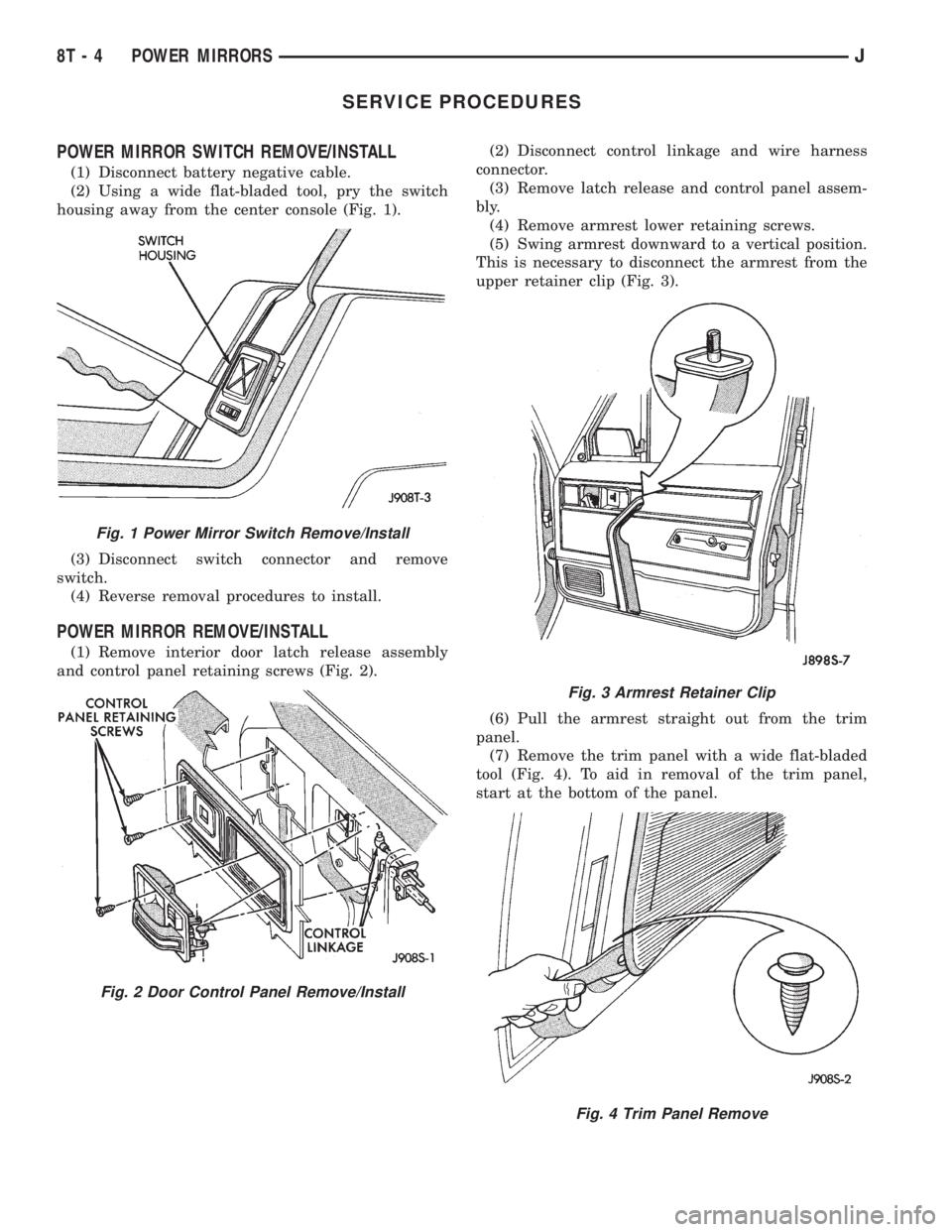
SERVICE PROCEDURES
POWER MIRROR SWITCH REMOVE/INSTALL
(1) Disconnect battery negative cable.
(2) Using a wide flat-bladed tool, pry the switch
housing away from the center console (Fig. 1).
(3) Disconnect switch connector and remove
switch.
(4) Reverse removal procedures to install.
POWER MIRROR REMOVE/INSTALL
(1) Remove interior door latch release assembly
and control panel retaining screws (Fig. 2).(2) Disconnect control linkage and wire harness
connector.
(3) Remove latch release and control panel assem-
bly.
(4) Remove armrest lower retaining screws.
(5) Swing armrest downward to a vertical position.
This is necessary to disconnect the armrest from the
upper retainer clip (Fig. 3).
(6) Pull the armrest straight out from the trim
panel.
(7) Remove the trim panel with a wide flat-bladed
tool (Fig. 4). To aid in removal of the trim panel,
start at the bottom of the panel.
Fig. 1 Power Mirror Switch Remove/Install
Fig. 2 Door Control Panel Remove/Install
Fig. 3 Armrest Retainer Clip
Fig. 4 Trim Panel Remove
8T - 4 POWER MIRRORSJ
Page 544 of 2198
POWER DISTRIBUTION
GENERAL INFORMATION
This section covers the Power Distribution Center
(PDC) and all circuits involved with it. For additional
information on system operation, refer to the appro-
priate section of the wiring diagrams.
DIAGRAM INDEX
Component Page
A/C Compressor Clutch Relay..............8W-11-3, 11
ABS Control Module.....................8W-11-6, 7
ABS Power Relay......................8W-11-3, 6
ABS Pump Motor Relay..................8W-11-3, 7
Automatic Shut Down Relay................8W-11-3, 9
Chime/Buzzer Module..................8W-11-10, 14
Circuit Breaker Cavity 16 (Fuse Block)..........8W-11-13
Combination Flasher......................8W-11-17
Daytime Running Lamp Module.............8W-11-5, 10
Diode D101............................8W-11-6
Engine Starter Motor Relay................8W-11-3, 4
Fuel Pump Relay.......................8W-11-3, 8
Fuse 1 (PDC)..........................8W-11-13
Fuse 3 (PDC)..........................8W-11-12
Fuse 4 (Fuse Block)......................8W-11-14
Fuse 4 (PDC)..........................8W-11-15
Fuse 5 (PDC)..........................8W-11-14
Fuse 6 (PDC)....................8W-11-4, 7, 10, 15
Fuse 7 (Fuse Block).......................8W-11-7
Fuse 7 (PDC)...........................8W-11-4
Fuse 8 (PDC)...........................8W-11-7
Fuse 9 (Fuse Block)......................8W-11-12
Fuse 9 (PDC)..........................8W-11-13
Fuse 10 (PDC)........................8W-11-6, 8
Fuse 11 (Fuse Block).....................8W-11-13
Fuse 11 (PDC).........................8W-11-10
Fuse 12 (PDC).........................8W-11-15Component Page
Fuse 13 (PDC)..........................8W-11-4
Fuse 14 (PDC)..........................8W-11-8
Fuse 15 (Fuse Block).....................8W-11-14
Fuse 15 (PDC)..........................8W-11-8
Fuse 16 (PDC).........................8W-11-12
Fuse 17 (Fuse Block).....................8W-11-10
Headlamp Delay Module.................8W-11-10, 14
Headlamp Switch........................8W-11-14
Headlamp Dimmer Switch..................8W-11-14
Horn Rear Window Relay..................8W-11-17
Horn Relay............................8W-11-17
Ignition Switch...................8W-11-4, 7, 10, 15
In-Line Circuit Breaker (Stop Lamp Relay)........8W-11-13
LCD Illumination Relay....................8W-11-17
Overhead Console.....................8W-11-10, 14
Powertrain Control Module..........8W-11-4, 5, 8, 9, 11
Power Distribution Center...................8W-11-2
Power Door Lock Relay...................8W-11-16
Power Door Unlock Relay..................8W-11-16
Radiator Fan Control Relay................8W-11-3, 11
Remote Keyless Entry Module.............8W-11-10, 12
Relay Center...........................8W-11-16
Telltale Connector (I.P. Cluster)..........8W-11-6, 10, 12
Torque Converter Clutch (TCC) Relay...........8W-11-15
Transmission Control Module...............8W-11-5, 8
J8W-11 POWER DISTRIBUTIONÐXJ VEHICLES 8W - 11 - 1