four wheel drive JEEP CHEROKEE 1995 Service Repair Manual
[x] Cancel search | Manufacturer: JEEP, Model Year: 1995, Model line: CHEROKEE, Model: JEEP CHEROKEE 1995Pages: 2198, PDF Size: 82.83 MB
Page 10 of 2198
JUMP STARTING, TOWING AND HOISTING
INDEX
page page
Four-Wheel-Drive Vehicle Towing............. 12
Ground Clearance and Ramp Angle............ 11
Hoisting Recommendations.................. 10
Jump Starting Procedure..................... 9Towing Recommendations................... 10
Towing When Keys Are Not Available.......... 13
Two-Wheel-Drive Vehicle TowingÐXJ.......... 11
JUMP STARTING PROCEDURE
WARNING: DO NOT ATTEMPT TO PUSH OR TOW A
VEHICLE TO START THE ENGINE. UNBURNED
FUEL COULD ENTER THE EXHAUST CATALYTIC
CONVERTER AND IGNITE AFTER THE ENGINE IS
STARTED. THIS COULD CAUSE THE CONVERTER
TO OVERHEAT AND RUPTURE.
WARNING: REVIEW ALL SAFETY PRECAUTIONS
AND WARNINGS IN GROUP 8A, BATTERY/START-
ING/CHARGING SYSTEMS DIAGNOSTICS.
DO NOT JUMP START A FROZEN BATTERY, PER-
SONAL INJURY CAN RESULT.
DO NOT JUMP START WHEN MAINTENANCE
FREE BATTERY INDICATOR DOT IS YELLOW OR
BRIGHT COLOR.
DO NOT JUMP START A VEHICLE WHEN THE
BATTERY FLUID IS BELOW THE TOP OF LEAD
PLATES.
DO NOT ALLOW JUMPER CABLE CLAMPS TO
TOUCH EACH OTHER WHEN CONNECTED TO A
BOOSTER SOURCE.
DO NOT USE OPEN FLAME NEAR BATTERY.
REMOVE METALLIC JEWELRY WORN ON HANDS
OR WRISTS TO AVOID INJURY BY ACCIDENTAL
ARCING OF BATTERY CURRENT.
WHEN USING A HIGH OUTPUT BOOSTING DE-
VICE, DO NOT ALLOW BATTERY VOLTAGE TO EX-
CEED 16 VOLTS. REFER TO INSTRUCTIONS
PROVIDED WITH DEVICE BEING USED.
CAUTION: When using another vehicle as a
booster, do not allow vehicles to touch. Electrical
systems can be damaged on either vehicle.
TO JUMP START A DISABLED VEHICLE:
(1) Raise hood on disabled vehicle and visually in-
spect engine compartment for:
²Battery cable clamp condition, clean if necessary.
²Frozen battery.
²Yellow or bright color test indicator, if equipped.
²Low battery fluid level.
²Generator drive belt condition and tension.²Fuel fumes or leakage, correct if necessary.
CAUTION: If the cause of starting problem on dis-
abled vehicle is severe, damage to booster vehicle
charging system can result.
(2) When using another vehicle as a booster
source, turn off all accessories, place gear selector in
park or neutral, set park brake and operate engine at
1200 rpm.
(3) On disabled vehicle, place gear selector in park
or neutral and set park brake. Turn off all accesso-
ries.
(4) Connect jumper cables to booster battery. RED
clamp to positive terminal (+). BLACK clamp to neg-
ative terminal (-). DO NOT allow clamps at opposite
end of cables to touch, electrical arc will result. Re-
view all warnings in this procedure.
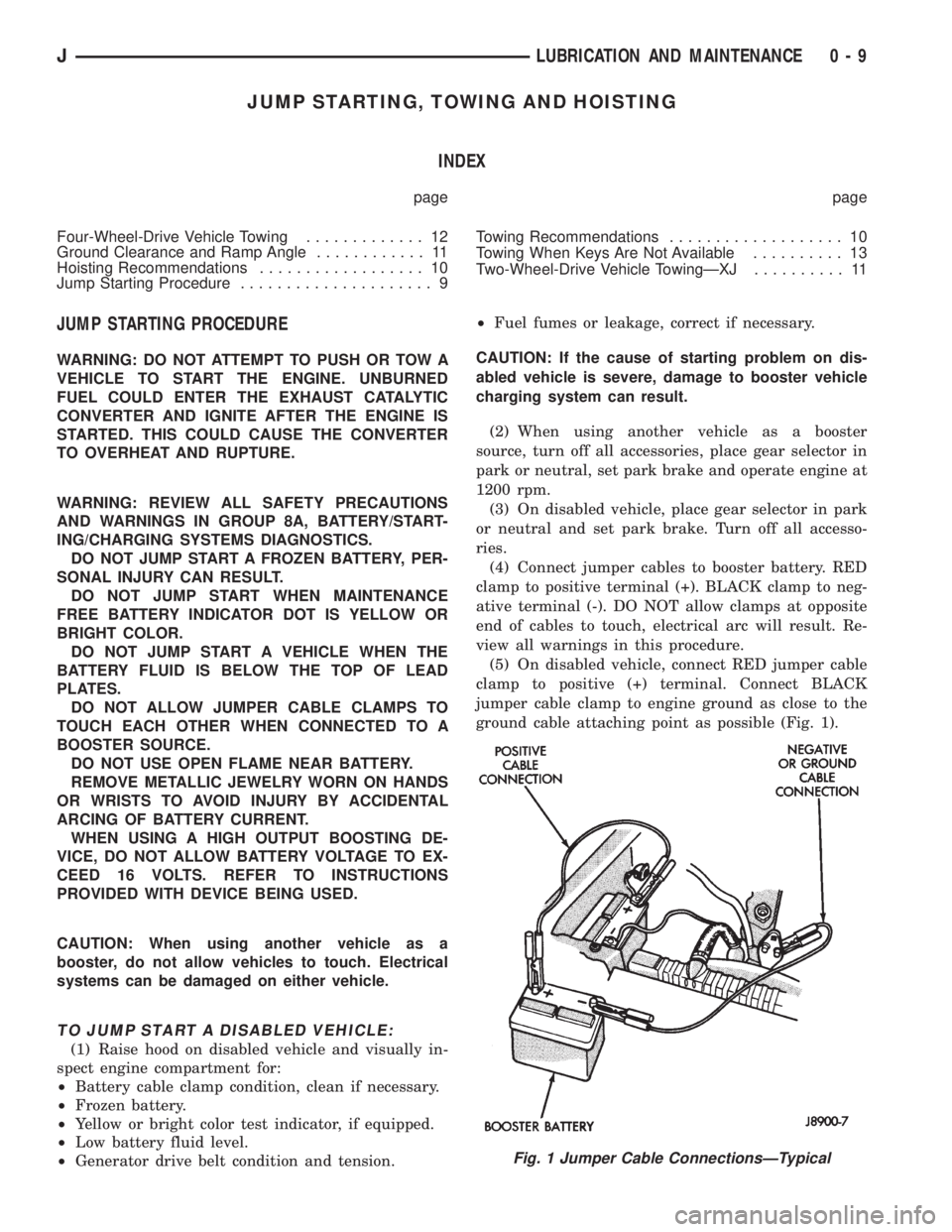
(5) On disabled vehicle, connect RED jumper cable
clamp to positive (+) terminal. Connect BLACK
jumper cable clamp to engine ground as close to the
ground cable attaching point as possible (Fig. 1).
Fig. 1 Jumper Cable ConnectionsÐTypical
JLUBRICATION AND MAINTENANCE 0 - 9
Page 13 of 2198
TOWING-FRONT END LIFTED (SLING-TYPE)
CAUTION: Many vehicles are equipped with air
dams, spoilers, and/or ground effect panels. To
avoid component damage, a wheel-lift towing vehi-
cle or a flat-bed hauling vehicle is recommended.
If a 2WD XJ vehicle cannot be towed with the rear
wheels lifted, it can be towed with the front wheels
lifted.
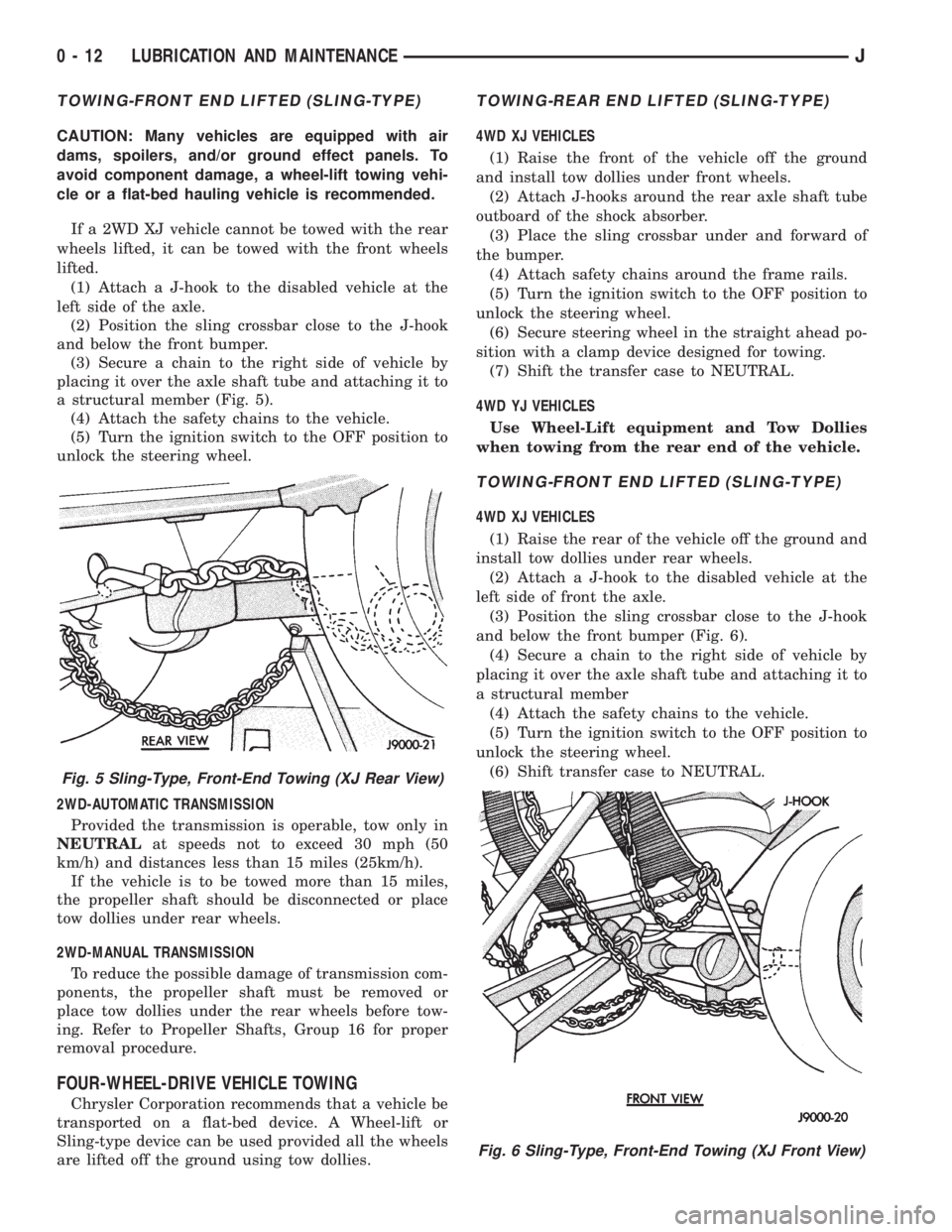
(1) Attach a J-hook to the disabled vehicle at the
left side of the axle.
(2) Position the sling crossbar close to the J-hook
and below the front bumper.
(3) Secure a chain to the right side of vehicle by
placing it over the axle shaft tube and attaching it to
a structural member (Fig. 5).
(4) Attach the safety chains to the vehicle.
(5) Turn the ignition switch to the OFF position to
unlock the steering wheel.
2WD-AUTOMATIC TRANSMISSION
Provided the transmission is operable, tow only in
NEUTRALat speeds not to exceed 30 mph (50
km/h) and distances less than 15 miles (25km/h).
If the vehicle is to be towed more than 15 miles,
the propeller shaft should be disconnected or place
tow dollies under rear wheels.
2WD-MANUAL TRANSMISSION
To reduce the possible damage of transmission com-
ponents, the propeller shaft must be removed or
place tow dollies under the rear wheels before tow-
ing. Refer to Propeller Shafts, Group 16 for proper
removal procedure.
FOUR-WHEEL-DRIVE VEHICLE TOWING
Chrysler Corporation recommends that a vehicle be
transported on a flat-bed device. A Wheel-lift or
Sling-type device can be used provided all the wheels
are lifted off the ground using tow dollies.
TOWING-REAR END LIFTED (SLING-TYPE)
4WD XJ VEHICLES
(1) Raise the front of the vehicle off the ground
and install tow dollies under front wheels.
(2) Attach J-hooks around the rear axle shaft tube
outboard of the shock absorber.
(3) Place the sling crossbar under and forward of
the bumper.
(4) Attach safety chains around the frame rails.
(5) Turn the ignition switch to the OFF position to
unlock the steering wheel.
(6) Secure steering wheel in the straight ahead po-
sition with a clamp device designed for towing.
(7) Shift the transfer case to NEUTRAL.
4WD YJ VEHICLES
Use Wheel-Lift equipment and Tow Dollies
when towing from the rear end of the vehicle.
TOWING-FRONT END LIFTED (SLING-TYPE)
4WD XJ VEHICLES
(1) Raise the rear of the vehicle off the ground and
install tow dollies under rear wheels.
(2) Attach a J-hook to the disabled vehicle at the
left side of front the axle.
(3) Position the sling crossbar close to the J-hook
and below the front bumper (Fig. 6).
(4) Secure a chain to the right side of vehicle by
placing it over the axle shaft tube and attaching it to
a structural member
(4) Attach the safety chains to the vehicle.
(5) Turn the ignition switch to the OFF position to
unlock the steering wheel.
(6) Shift transfer case to NEUTRAL.
Fig. 5 Sling-Type, Front-End Towing (XJ Rear View)
Fig. 6 Sling-Type, Front-End Towing (XJ Front View)
0 - 12 LUBRICATION AND MAINTENANCEJ
Page 14 of 2198
4WD YJ VEHICLES
(1) Raise the rear of the vehicle off the ground and
install tow dollies under rear wheels.
CAUTION: Use tow chains with T-hooks for con-
necting to the disabled vehicle's frame rails. Never
use J-hooks.
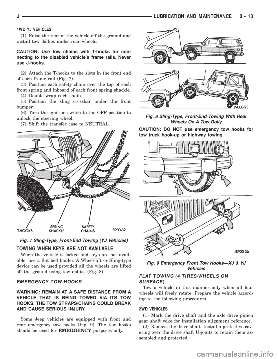
(2) Attach the T-hooks to the slots in the front end
of each frame rail (Fig. 7).
(3) Position each safety chain over the top of each
front spring and inboard of each front spring shackle.
(4) Double wrap each chain.
(5) Position the sling crossbar under the front
bumper.
(6) Turn the ignition switch to the OFF position to
unlock the steering wheel.
(7) Shift the transfer case to NEUTRAL.
TOWING WHEN KEYS ARE NOT AVAILABLE
When the vehicle is locked and keys are not avail-
able, use a flat bed hauler. A Wheel-lift or Sling-type
device can be used provided all the wheels are lifted
off the ground using tow dollies (Fig. 8).
EMERGENCY TOW HOOKS
WARNING: REMAIN AT A SAFE DISTANCE FROM A
VEHICLE THAT IS BEING TOWED VIA ITS TOW
HOOKS. THE TOW STRAPS/CHAINS COULD BREAK
AND CAUSE SERIOUS INJURY.
Some Jeep vehicles are equipped with front and
rear emergency tow hooks (Fig. 9). The tow hooks
should be used forEMERGENCYpurposes only.CAUTION: DO NOT use emergency tow hooks for
tow truck hook-up or highway towing.
FLAT TOWING (4 TIRES/WHEELS ON
SURFACE)
Tow a vehicle in this manner only when all four
wheels will freely rotate. Prepare the vehicle accord-
ing to the following procedures.
2WD VEHICLES
(1) Mark the drive shaft and the axle drive pinion
gear shaft yoke for installation alignment reference.
(2) Remove the drive shaft. Install a protective cov-
ering over the drive shaft U-joints to retain them as-
sembled and protected.
Fig. 7 Sling-Type, Front-End Towing (YJ Vehicles)
Fig. 8 Sling-Type, Front-End Towing With Rear
Wheels On A Tow Dolly
Fig. 9 Emergency Front Tow HooksÐXJ & YJ
Vehicles
JLUBRICATION AND MAINTENANCE 0 - 13
Page 37 of 2198
the opposite wheel. Wheels are attached to a hub/
bearings which bolts to the knuckles. The hub/bear-
ing is not serviceable and is replaced as a unit.
Steering knuckles pivot on replaceable ball studs at-
tached to the axle tube yokes.
The upper and lower suspension arms are different
lengths, with bushings at both ends. They bolt the
axle assembly to the body. The lower arms uses
shims at the body mount to allow for adjustment of
caster and drive shaft pinion angle. The suspension
arm travel is limited through the use of jounce
bumpers in compression and shocks absorbers in re-
bound.
Suspension components which use rubber bushings
should be tightened at vehicle ride height. This will
prevent premature failure of the bushing and main-
tain ride comfort. Bushings must never be lubricated.
The coil springs control ride quality and maintain
proper ride height. The coil springs mount up in the
fender shield which is part of the unitized body
bracket. A rubber isolator is located between the top
of the spring and the frame. The bottom of the spring
seats on a axle pad and is retained with a clip.
The shock absorbers dampen jounce and rebound of
the vehicle over various road conditions. The top of
the shock absorbers are bolted to the body. The bot-
tom of the shocks are bolted to the axle spring
bracket.
The stabilizer bar is used to minimize vehicle body
roll during turns. The spring steel bar helps to con-
trol the vehicle body in relationship to the suspen-
sion. The bar extends across the front underside of
the chassis and connects to the body rails. Links are
connected from the bar to the axle brackets. Stabi-
lizer bar mounts are isolated by rubber bushings.
The track bar is used to minimize front axle side-
to-side movement. The bar is attached to a frame rail
bracket with a ball stud and isolated with a bushing
at the axle bracket.
TUBE AXLE (2WD VEHICLES)
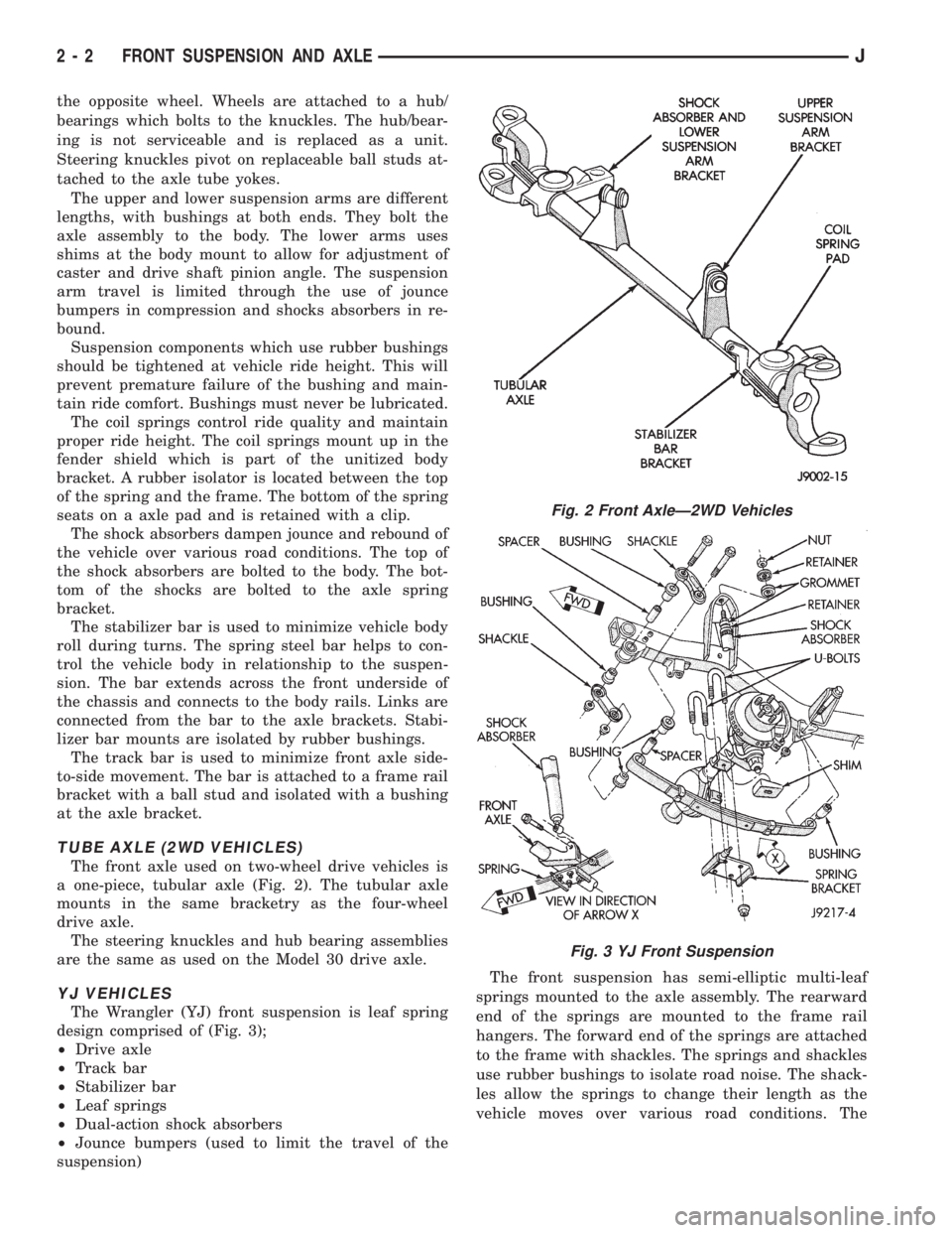
The front axle used on two-wheel drive vehicles is
a one-piece, tubular axle (Fig. 2). The tubular axle
mounts in the same bracketry as the four-wheel
drive axle.
The steering knuckles and hub bearing assemblies
are the same as used on the Model 30 drive axle.
YJ VEHICLES
The Wrangler (YJ) front suspension is leaf spring
design comprised of (Fig. 3);
²Drive axle
²Track bar
²Stabilizer bar
²Leaf springs
²Dual-action shock absorbers
²Jounce bumpers (used to limit the travel of the
suspension)The front suspension has semi-elliptic multi-leaf
springs mounted to the axle assembly. The rearward
end of the springs are mounted to the frame rail
hangers. The forward end of the springs are attached
to the frame with shackles. The springs and shackles
use rubber bushings to isolate road noise. The shack-
les allow the springs to change their length as the
vehicle moves over various road conditions. The
Fig. 2 Front AxleÐ2WD Vehicles
Fig. 3 YJ Front Suspension
2 - 2 FRONT SUSPENSION AND AXLEJ
Page 57 of 2198
MODEL 30 AXLE AND TUBE AXLE (2WD)
INDEX
page page
Axle Bushing Replacement.................. 34
Axle ShaftÐCardan U-Joint.................. 26
Backlash and Contact Pattern Analysis......... 45
Cleaning/Inspection........................ 37
Differential and Pinion Measurement........... 40
Differential Assembly....................... 38
Differential Disassembly.................... 35
Differential Installation...................... 44
Differential Removal....................... 34
Differential Shim Pack Measurement and
Adjustment............................ 43
Drive Axle Assembly ReplacementÐXJ Vehicles . . 23
Drive Axle Assembly ReplacementÐYJ Vehicles . . 24Final Assembly........................... 46
Hub Bearing and Axle Shaft................. 25
Information.............................. 22
Inner Axle Shaft Oil Seal Replacement......... 35
Lubricant Change......................... 23
Lubricant Specifications..................... 22
Pinion Gear Assembly/Installation............. 42
Pinion Gear Depth Information............... 39
Pinion Removal/Disassembly................. 36
Pinion Seal Replacement................... 25
Steering Knuckle and Ball Studs.............. 32
Vacuum Disconnect AxleÐYJ Vehicles......... 27
INFORMATION
The Model 30 front axles consists of a cast iron dif-
ferential housing with axle shaft tubes extending
from either side. The tubes are pressed into the dif-
ferential housing and welded.
The integral type housing, hypoid gear design has
the centerline of the pinion set above the centerline
of the ring gear.
The axle has a fitting for a vent hose used to re-
lieve internal pressure caused by lubricant vaporiza-
tion and internal expansion.
The axles are equipped with semi-floating axle
shafts, meaning that loads are supported by the hub
bearings. The axle shafts are retained by nuts at the
hub bearings. The hub bearings are bolted to the
steering knuckle at the outboard end of the axle tube
yoke. The hub bearings are serviced as an assembly.
The axles are equipped with ABS brake sensors.
The sensors are attached to the knuckle assemblies
and tone rings are pressed on the axle shaft.Use
care when removing axle shafts as NOT to dam-
age the tone wheel or the sensor.
The stamped steel cover provides a means for in-
spection and servicing the differential.
The Model 30 axle has the assembly part number
and gear ratio listed on a tag. The tag is attached to
the housing cover. Build date identification codes are
stamped on the axle shaft tube cover side.
The differential case is a one-piece design. The dif-
ferential pinion mate shaft is retained with a roll
pin. Differential bearing preload and ring gear back-
lash is adjusted by the use of shims (select thick-
ness). The shims are located between the differential
bearing cones and case. Pinion bearing preload is set
and maintained by the use of collapsible spacer.
COMMAND-TRACÐYJ VEHICLES
The Command-Trac system is a vacuum disconnect
axle. The system has a two-piece axle shaft coupled
together by a shift collar. For two-wheel drive opera-
tion, the vacuum motor and shift fork disengages the
axle shaft splines. For four-wheel drive operation, the
vacuum motor and shift fork engages the axle
splines.
SELEC-TRACÐXJ VEHICLES
The Selec-Trac system is a non-disconnect axle.
Shifting from two-wheel to four-wheel drive is done
at the transfer case.
For XJ vehicles equipped withSelec-Tracand
ABS brake system, refer to Group 5ÐBrakes for ad-
ditional service information.
LUBRICANT SPECIFICATIONS
Multi-purpose, hypoid gear lubricant should be
used for Model 30 axles. The lubricant should have
MIL-L-2105C and API GL 5 quality specifications.
MOPARtHypoid Gear Lubricant conforms to both of
these specifications.
²The factory fill for the Model 30 axle is SAE Ther-
mally Stable 80W-90 gear lubricant.Do not use
heavier weight lubricant, this will cause axle
engagement difficulties.
²The factory installed lubricant quantity for the
NON-DISCONNECT TYPE AXLE is 1.48 L (3.13
pts.).
²The factory installed lubricant quantity for the
VACUUM-DISCONNECT TYPE AXLE is 1.65 L (3.76
pts.).
Refer to Group 0, Lubrication and Maintenance for
additional information regarding temperature range,
viscosity and fluid level.
2 - 22 FRONT SUSPENSION AND AXLEJ
Page 100 of 2198
(7) Disconnect the brake hose at the axle junction
block.Do not disconnect the wheel cylinder tub-
ing fittings.
(8) Disconnect the track bar at the axle bracket.
(9) Support the axle with a hydraulic jack under
the differential. Raise the axle just enough to relieve
the axle weight from the springs.
(10) Remove the spring U-bolts from the plate
brackets.
(11) Loosen BUT DO NOT REMOVE the bolts that
attach the spring front pivot at the frame rail brack-
ets. This will allow the springs to pivot without bind-
ing on the bushings.
(12) Disconnect shackle from the springs and lower
the springs to the surface.
(13) Lower the jack enough to remove the axle.
INSTALLATION
CAUTION: Suspension components with rubber
bushings should be tightened with the vehicle at
normal height. It is important to have the springs
supporting the weight of the vehicle when the fas-
teners are torqued. If springs are not at their normal
ride position, vehicle ride comfort could be affected
and premature bushing wear may occur. Rubber
bushings must never be lubricated.
(1) Support the axle on a hydraulic jack under the
differential. Position the axle under the vehicle.
(2) Raise the springs and install the spring shackle
bolts.Do not tighten at this time.
(3) Lower the axle and align the spring center
bolts with the locating holes in the axle pads and
plate brackets.
(4) Install the spring U-bolts through the plate
brackets and tighten to 122 Nzm (90 ft. lbs.) torque.
(5) Connect the track bar to the axle bracket and
install the bolt. Do not tighten at this time.
It is important that the springs support the
weight of the vehicle when the track bar is con-
nected. If the springs are not at their usual po-
sition, vehicle ride comfort could be affected.
(6) Connect the brake hose at the axle junction
block.
(7) Install the shock absorbers to the axle brackets
and tighten to 61 Nzm (45 ft. lbs.) torque.
(8) Connect the parking brake cables at the equal-
izer or backing plate.
(9) Connect the vent hose to the tube fitting.
(10) Align the reference marks and connect the
drive shaft to the axle yoke. Tighten the U-joint
clamp bolts to 19 Nzm (14 ft. lbs.) torque.
(11) Check differential lubricant and add if neces-
sary.
(12) Install the wheel and tire.
(13) Bleed the brakes.
(14) Remove the supports and lower the vehicle.(15) Tighten the spring front pivot bolt/nut to 142
Nzm (105 ft. lbs.) torque. Tighten the spring shackle
bolt/nut to 135 Nzm (100 ft. lbs.) torque.
(16) Tighten the track bar bolt at the axle bracket
to 142 Nzm (105 ft. lbs.) torque.
PINION SHAFT SEAL REPLACEMENT
REMOVAL
(1) Raise and support the vehicle.
(2) Remove wheel and tire assemblies.
(3) Mark the drive shaft yoke and pinion yoke for
installation alignment reference.
(4) Remove the drive shaft from the yoke.
(5) Rotate the pinion gear three or four times.
Make sure brakes are not dragging during this
procedure.
(6) Measure the amount of torque (in Newton-
meters or inch-pounds) necessary to rotate the pinion
gear with a torque wrench. Note the torque for in-
stallation reference.It must be known to properly
adjust the pinion gear bearing preload torque
after seal installation.
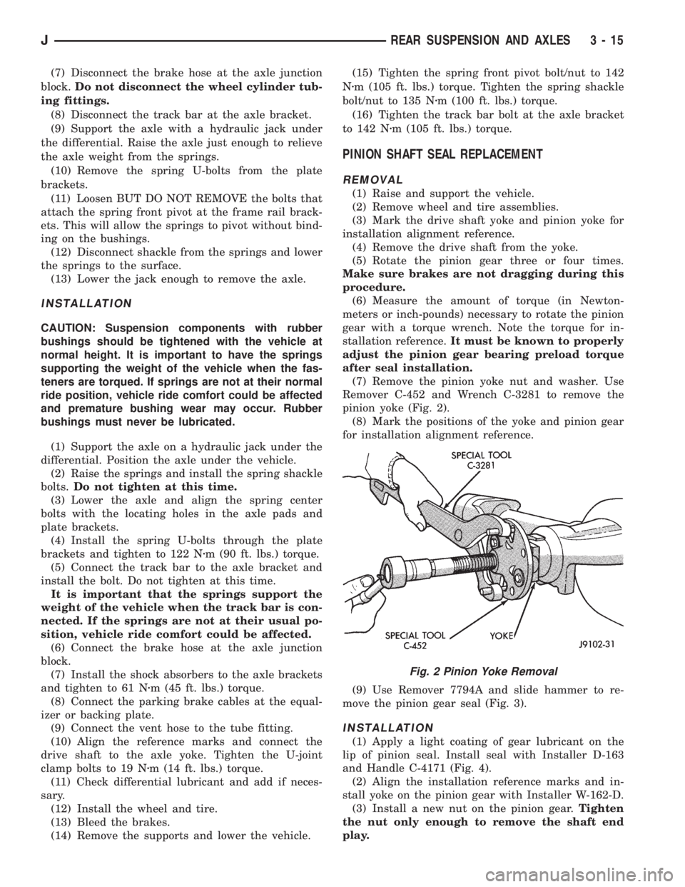
(7) Remove the pinion yoke nut and washer. Use
Remover C-452 and Wrench C-3281 to remove the
pinion yoke (Fig. 2).
(8) Mark the positions of the yoke and pinion gear
for installation alignment reference.
(9) Use Remover 7794A and slide hammer to re-
move the pinion gear seal (Fig. 3).
INSTALLATION
(1) Apply a light coating of gear lubricant on the
lip of pinion seal. Install seal with Installer D-163
and Handle C-4171 (Fig. 4).
(2) Align the installation reference marks and in-
stall yoke on the pinion gear with Installer W-162-D.
(3) Install a new nut on the pinion gear.Tighten
the nut only enough to remove the shaft end
play.
Fig. 2 Pinion Yoke Removal
JREAR SUSPENSION AND AXLES 3 - 15
Page 189 of 2198
(4) Install new spring nuts on wheel studs.
(5) Install wheel and lower vehicle.
DISC BRAKE ROTOR THICKNESS
Rotor minimum usable thickness is 22.7 mm (0.89
in.). This dimension is either cast, or stamped on the
rotor hub, or outer edge.
Measure rotor thickness at the center of the brake-
shoe contact surface.
Replace the rotor if worn below minimum thick-
ness. Also replace the rotor if refinishing would re-
duce thickness below the allowable minimum.
DISC BRAKE ROTOR RUNOUT
Check rotor lateral runout whenever pedal pulsa-
tion, or rapid, uneven brakelining wear has occurred.
On 4-wheel drive models, the rotor must be se-
curely clamped to the hub to ensure an accurate
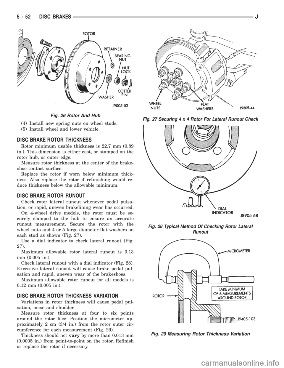
runout measurement. Secure the rotor with the
wheel nuts and 4 or 5 large diameter flat washers on
each stud as shown (Fig. 27).
Use a dial indicator to check lateral runout (Fig.
27).
Maximum allowable rotor lateral runout is 0.13
mm (0.005 in.).
Check lateral runout with a dial indicator (Fig. 28).
Excessive lateral runout will cause brake pedal pul-
sation and rapid, uneven wear of the brakeshoes.
Maximum allowable rotor runout for all models is
0.12 mm (0.005 in.).
DISC BRAKE ROTOR THICKNESS VARIATION
Variations in rotor thickness will cause pedal pul-
sation, noise and shudder.
Measure rotor thickness at four to six points
around the rotor face. Position the micrometer ap-
proximately 2 cm (3/4 in.) from the rotor outer cir-
cumference for each measurement (Fig. 29).
Thickness should notvaryby more than 0.013 mm
(0.0005 in.) from point-to-point on the rotor. Refinish
or replace the rotor if necessary.
Fig. 26 Rotor And HubFig. 27 Securing4x4Rotor For Lateral Runout Check
Fig. 28 Typical Method Of Checking Rotor Lateral
Runout
Fig. 29 Measuring Rotor Thickness Variation
5 - 52 DISC BRAKESJ
Page 314 of 2198
CRANKSHAFT POSITION SENSOR
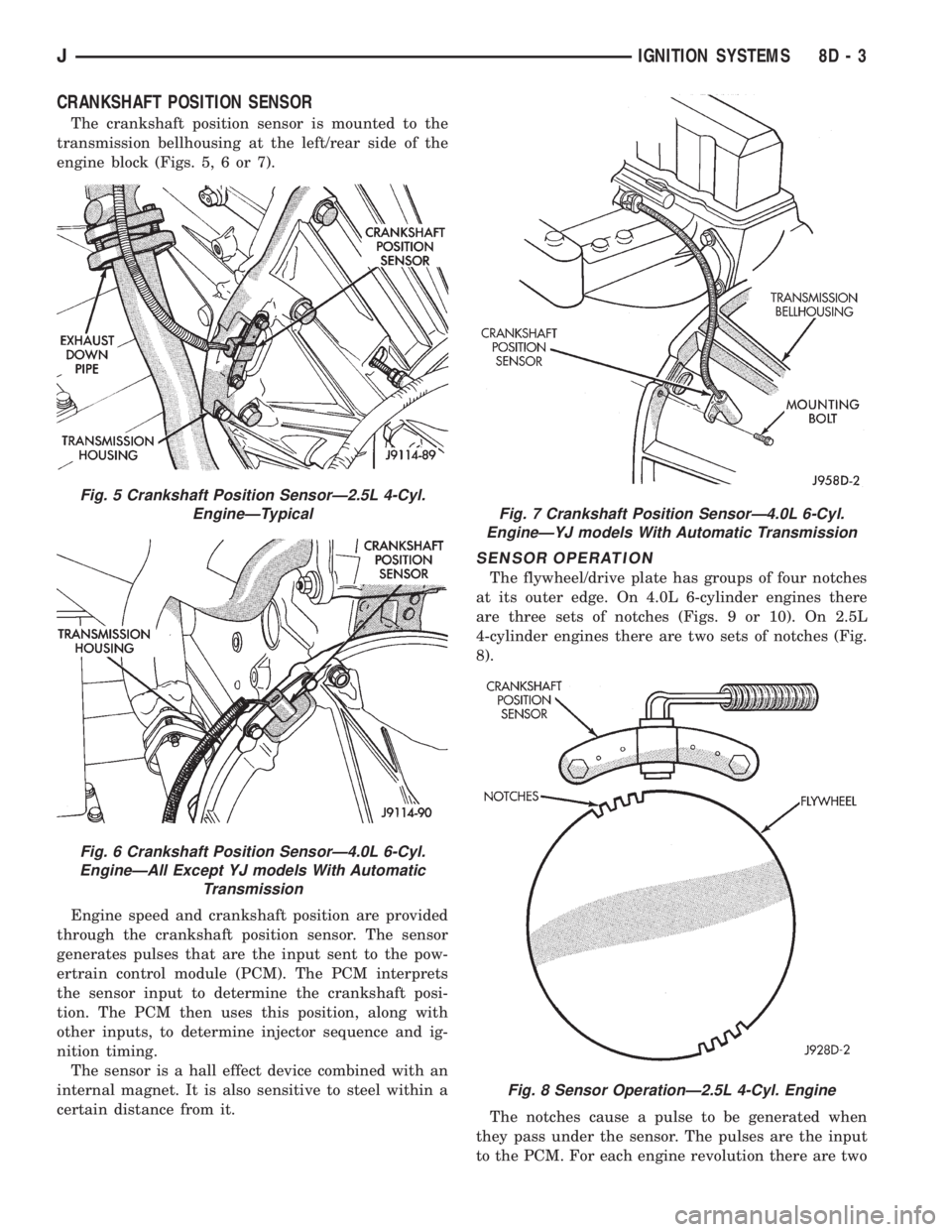
The crankshaft position sensor is mounted to the
transmission bellhousing at the left/rear side of the
engine block (Figs. 5, 6 or 7).
Engine speed and crankshaft position are provided
through the crankshaft position sensor. The sensor
generates pulses that are the input sent to the pow-
ertrain control module (PCM). The PCM interprets
the sensor input to determine the crankshaft posi-
tion. The PCM then uses this position, along with
other inputs, to determine injector sequence and ig-
nition timing.
The sensor is a hall effect device combined with an
internal magnet. It is also sensitive to steel within a
certain distance from it.
SENSOR OPERATION
The flywheel/drive plate has groups of four notches
at its outer edge. On 4.0L 6-cylinder engines there
are three sets of notches (Figs. 9 or 10). On 2.5L
4-cylinder engines there are two sets of notches (Fig.
8).
The notches cause a pulse to be generated when
they pass under the sensor. The pulses are the input
to the PCM. For each engine revolution there are two
Fig. 5 Crankshaft Position SensorÐ2.5L 4-Cyl.
EngineÐTypical
Fig. 6 Crankshaft Position SensorÐ4.0L 6-Cyl.
EngineÐAll Except YJ models With Automatic
Transmission
Fig. 7 Crankshaft Position SensorÐ4.0L 6-Cyl.
EngineÐYJ models With Automatic Transmission
Fig. 8 Sensor OperationÐ2.5L 4-Cyl. Engine
JIGNITION SYSTEMS 8D - 3
Page 344 of 2198
INSTRUMENT PANEL AND GAUGES
GROUP INDEX
INSTRUMENT PANEL AND GAUGESÐXJ...... 1INSTRUMENT PANEL AND GAUGESÐYJ..... 24
INSTRUMENT PANEL AND GAUGESÐXJ
CONTENTS
page page
DIAGNOSIS............................. 5
GENERAL INFORMATION.................. 1SERVICE PROCEDURES.................. 17
SPECIFICATIONS........................ 23
GENERAL INFORMATION
Following are general descriptions of major instru-
ment panel components. Refer to Group 8W - Wiring
Diagrams for complete circuit descriptions and dia-
grams.
INSTRUMENT PANEL
Modular instrument panel construction allows all
gauges and controls to be serviced from the front of
the panel. In addition, most instrument panel wiring
or heater and air conditioning components can be ac-
cessed without complete instrument panel removal. If
necessary, the instrument panel can be rolled-down
and removed from the vehicle as an assembly.
Removal of the instrument cluster bezel allows ac-
cess to the cluster assembly, most switches, the cli-
mate controls, and the radio. Removal of the cluster
assembly allows access to the individual gauges, illu-
mination and indicator lamp bulbs, printed circuits,
and most wiring.
Removal of the lower instrument panel allows ac-
cess to heater and air conditioning components, the
fuseblock module, the relay center, and other wiring
and electrical components. Those models equipped
with a driver's-side airbag restraint have a knee
blocker and reinforcement behind the driver's-side
lower instrument panel.
The instrument panel layout is mirror image for
left-hand and right-hand drive vehicles. In most
cases, the diagnosis and service procedures found in
this group are applicable to either vehicle. Although,most illustrations represent only the typical left-hand
drive version. Exceptions are clearly identified as
Right-Hand Drive (RHD).
INSTRUMENT CLUSTERS
Two basic instrument cluster options are offered on
XJ (Cherokee) models. One is referred to as a low-
line cluster, and the other is referred to as a high-
line cluster. Each cluster is divided into two areas:
the gauge area, and the tell-tale area. Each area is
served by a separate printed circuit and wiring con-
nector. Some variations of each cluster exist due to
optional equipment and regulatory requirements.
The low-line cluster includes the following gauges:
²fuel gauge
²speedometer/odometer.
The low-line cluster includes provisions for the fol-
lowing indicator lamps:
²anti-lock brake system lamp
²brake warning lamp
²coolant temperature warning lamp
²four-wheel drive indicator lamps
²generator warning lamp
²headlamp high beam indicator lamp
²low oil pressure warning lamp
²low washer fluid warning lamp
²malfunction indicator (Check Engine) lamp
²seat belt reminder lamp
²turn signal indicator lamps
²upshift indicator lamp.
JINSTRUMENT PANEL AND GAUGES 8E - 1
Page 345 of 2198
The high-line cluster includes the following gauges:
²coolant temperature gauge
²fuel gauge
²oil pressure gauge
²speedometer/odometer
²tachometer
²trip odometer
²voltmeter.
The high-line cluster includes provisions for the fol-
lowing indicator lamps:
²anti-lock brake system lamp
²brake warning lamp
²four-wheel drive indicator lamps
²headlamp high beam indicator lamp
²low fuel warning lamp
²low washer fluid warning lamp
²malfunction indicator (Check Engine) lamp
²seat belt reminder lamp
²turn signal indicator lamps
²upshift indicator lamp.
GAUGES
With the ignition switch in the ON or START posi-
tion, voltage is supplied to all gauges through the in-
strument cluster gauge area printed circuit. With the
ignition switch in the OFF position, voltage is not
supplied to the gauges. A gauge pointer may remain
within the gauge scale after the ignition switch is
OFF. However, the gauges do not accurately indicate
any vehicle condition unless the ignition switch is
ON.
All gauges except the odometer are air core mag-
netic units. Two fixed electromagnetic coils are lo-
cated within the gauge. These coils are wrapped at
right angles to each other around a movable perma-
nent magnet. The movable magnet is suspended
within the coils on one end of a shaft. The gauge nee-
dle is attached to the other end of the shaft.
One of the coils has a fixed current flowing through
it to maintain a constant magnetic field strength.
Current flow through the second coil changes, which
causes changes in its magnetic field strength. The
current flowing through the second coil can be
changed by:
²a variable resistor-type sending unit (fuel level,
coolant temperature, or oil pressure)
²changes in electrical system voltage (voltmeter)
²electronic control circuitry (speedometer/odometer,
tachometer).
The gauge needle moves as the movable permanent
magnet aligns itself to the changing magnetic fields
created around it by the electromagnets.
COOLANT TEMPERATURE GAUGE
The coolant temperature gauge gives an indication
of engine coolant temperature. The coolant tempera-
ture sending unit is a thermistor that changes elec-
trical resistance with changes in engine coolanttemperature. High sending unit resistance causes
low coolant temperature readings. Low resistance
causes high coolant temperature readings.
The gauge will read at the high end of the scale
when the ignition switch is turned to the START po-
sition. This is caused by the bulb test circuit wiring
provision. The same wiring is used for the high-line
cluster with a coolant temperature gauge and the
low-line cluster with a coolant temperature warning
lamp. Sending unit resistance values are shown in a
chart in Specifications.
FUEL GAUGE
The fuel gauge gives an indication of the level of
fuel in the fuel tank. The fuel gauge sending unit has
a float attached to a swing-arm in the fuel tank. The
float moves up or down within the fuel tank as fuel
level changes. As the float moves, an electrical con-
tact on the swing-arm wipes across a resistor coil,
which changes sending unit resistance. High sending
unit resistance causes low fuel level readings. Low
resistance causes high fuel level readings. Sending
unit resistance values are shown in a chart in Spec-
ifications.
OIL PRESSURE GAUGE
The oil pressure gauge gives an indication of en-
gine oil pressure. The combination oil pressure send-
ing unit contains a flexible diaphragm. The
diaphragm moves in response to changes in engine
oil pressure. As the diaphragm moves, sending unit
resistance increases or decreases. High resistance on
the gauge side of the sending unit causes high oil
pressure readings. Low resistance causes low oil
pressure readings. Sending unit resistance values are
shown in a chart in Specifications.
SPEEDOMETER/ODOMETER
The speedometer/odometer gives an indication of
vehicle speed and travel distance. The speedometer
receives a vehicle speed pulse signal from the Vehicle
Speed Sensor (VSS). An electronic integrated circuit
contained within the speedometer reads and analyzes
the pulse signal. It then adjusts the ground path re-
sistance of one electromagnet in the gauge to control
needle movement. It also sends signals to an electric
stepper motor to control movement of the odometer
number rolls. Frequency values for the pulse signal
are shown in a chart in Specifications.
The VSS is mounted to an adapter near the trans-
mission (two-wheel drive) or transfer case (four-wheel
drive) output shaft. The sensor is driven through the
adapter by a speedometer pinion gear. The adapter
and pinion vary with transmission, transfer case,
axle ratio and tire size. Refer to Group 21 - Trans-
mission and Transfer Case for more information.
8E - 2 INSTRUMENT PANEL AND GAUGESÐXJJ