fuel filter location JEEP CHEROKEE 1995 Service Repair Manual
[x] Cancel search | Manufacturer: JEEP, Model Year: 1995, Model line: CHEROKEE, Model: JEEP CHEROKEE 1995Pages: 2198, PDF Size: 82.83 MB
Page 16 of 2198
ENGINE MAINTENANCE
INDEX
page page
Accessory Drive Belt....................... 21
Air Cleaner Element....................... 18
Air-Conditioner Compressor.................. 21
Battery................................. 20
Crankcase Ventilation System................ 19
Emission Control System................... 20
Engine Break-In.......................... 15
Engine Cooling System..................... 18
Engine Oil.............................. 15Engine Oil Change and Filter Replacement...... 16
Engine Oil Filter.......................... 17
Engine Supports.......................... 21
Exhaust System.......................... 21
Fuel Filter............................... 19
Fuel Usage StatementÐGas Engines.......... 19
Ignition Cables, Distributor Cap and Rotor....... 20
Rubber and Plastic Component Inspection....... 20
Spark Plugs............................. 20
ENGINE BREAK-IN
CAUTION: Wide open throttle operation in low
gears, before engine break-in period is complete,
can damage engine.
After first starting a new engine, allow it to idle for
15 seconds before shifting into a drive gear. Also:
²Drive the vehicle at varying speeds less than 88
km/h (55 mph) for the first 480 km (300 miles).
²Avoid fast acceleration and sudden stops.
²Do not drive at full-throttle for extended periods of
time.
²Do not drive at constant speeds.
²Do not idle the engine excessively.
A special break-in engine oil is not required. The
original engine oil installed is a high quality, energy
conserving lubricant. Special break-in oils are not
recommended. These oils could interfere with the
normal piston ring seating process.
New engines tend to consume more fuel and oil un-
til after the break-in period has ended.
ENGINE OIL
WARNING: NEW OR USED ENGINE OIL CAN BE IR-
RITATING TO THE SKIN. AVOID PROLONGED OR
REPEATED SKIN CONTACT WITH ENGINE OIL.
CONTAMINANTS IN USED ENGINE OIL, CAUSED BY
INTERNAL COMBUSTION, CAN BE HAZARDOUS TO
YOUR HEALTH. THOROUGHLY WASH EXPOSED
SKIN WITH SOAP AND WATER.
DO NOT WASH SKIN WITH GASOLINE, DIESEL
FUEL, THINNER, OR SOLVENTS, HEALTH PROB-
LEMS CAN RESULT.
DO NOT POLLUTE, DISPOSE OF USED ENGINE
OIL PROPERLY. CONTACT YOUR DEALER OR GOV-
ERNMENT AGENCY FOR LOCATION OF COLLEC-
TION CENTER IN YOUR AREA.
ENGINE OIL SPECIFICATION
CAUTION: Do not use non-detergent or straight
mineral oil when adding or changing crankcase lu-
bricant. Engine failure can result.
API SERVICE GRADE CERTIFIED
Use an engine oil that is API Service Grade Certi-
fied or an oil that conforms to the API Service Grade
SH or SH/CD. MOPAR provides engine oils that con-
form to all of these service grades.
SAE VISCOSITY
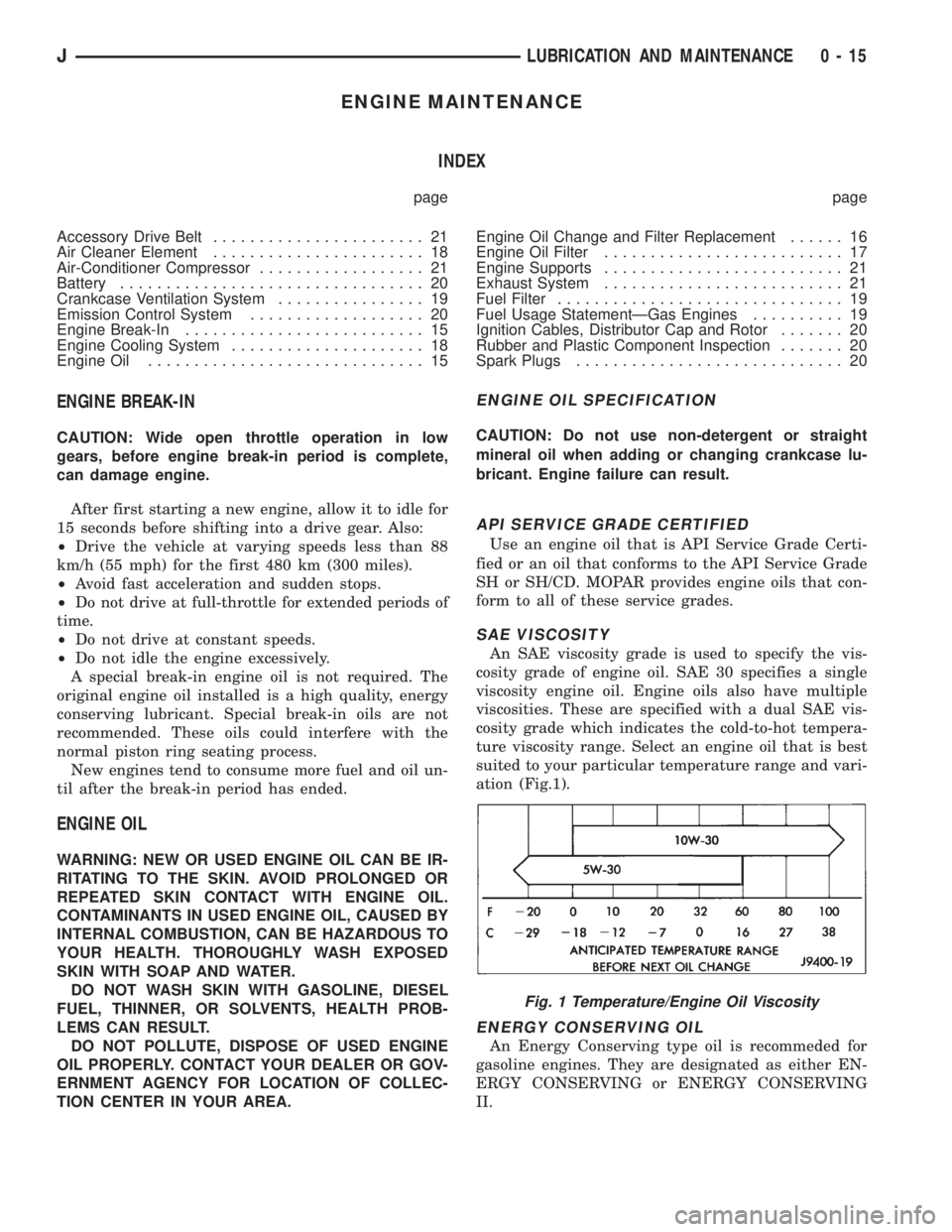
An SAE viscosity grade is used to specify the vis-
cosity grade of engine oil. SAE 30 specifies a single
viscosity engine oil. Engine oils also have multiple
viscosities. These are specified with a dual SAE vis-
cosity grade which indicates the cold-to-hot tempera-
ture viscosity range. Select an engine oil that is best
suited to your particular temperature range and vari-
ation (Fig.1).
ENERGY CONSERVING OIL
An Energy Conserving type oil is recommeded for
gasoline engines. They are designated as either EN-
ERGY CONSERVING or ENERGY CONSERVING
II.
Fig. 1 Temperature/Engine Oil Viscosity
JLUBRICATION AND MAINTENANCE 0 - 15
Page 19 of 2198
USED ENGINE OIL DISPOSAL
Care should be exercised when disposing used en-
gine oil after it has been drained from a vehicle en-
gine. Refer to the WARNING listed above.
ENGINE COOLING SYSTEM
WARNINGS AND PRECAUTIONS
WARNING: ANTIFREEZE IS AN ETHYLENE GLYCOL
BASE COOLANT AND IS HARMFUL IF SWAL-
LOWED OR INHALED. IF SWALLOWED, DRINK
TWO GLASSES OF WATER AND INDUCE VOMIT-
ING. IF INHALED, MOVE TO FRESH AIR AREA.
SEEK MEDICAL ATTENTION IMMEDIATELY. DO NOT
STORE IN OPEN OR UNMARKED CONTAINERS.
WASH SKIN AND CLOTHING THOROUGHLY AFTER
COMING IN CONTACT WITH ETHYLENE GLYCOL.
KEEP OUT OF REACH OF CHILDREN.
DISPOSE OF GLYCOL BASE COOLANT PROP-
ERLY, CONTACT YOUR DEALER OR GOVERNMENT
AGENCY FOR LOCATION OF COLLECTION CENTER
IN YOUR AREA.
DO NOT OPEN A COOLING SYSTEM WHEN THE
ENGINE IS AT RUNNING TEMPERATURE, PER-
SONAL INJURY CAN RESULT.
AVOID RADIATOR COOLING FAN WHEN ENGINE
COMPARTMENT RELATED SERVICE IS PER-
FORMED, PERSONAL INJURY CAN RESULT.
CAUTION: Do not use straight antifreeze as engine
coolant, inadequate engine running temperatures
can result.
Do not operate vehicle without proper concentra-
tion of recommended ethylene glycol coolant, high
running temperatures and cooling system corrosion
can result.
The engine cooling system will develop internal
pressure of 97 to 123 kPa (14 to 18 psi) at normal op-
erating temperature. Allow the vehicle approximately
one half hour to cool off before opening the cooling
system. As an indicator of pressure, squeeze the up-
per radiator hose between index finger and thumb. If
it collapses with little effort the system would have
low internal pressure and should be safe to open to
the first safety notch of the radiator cap. Refer to
Group 7, Cooling System.
COOLING SYSTEM INSPECTION
Coolant level should be inspected when other en-
gine compartment service is performed or when cool-
ant leak is suspected. With the engine at normal
operating temperature, observe the coolant level in
thecoolant recovery bottle. The coolant level mustbe at least above the ADD mark and preferably at
the FULL mark. Add coolant to the coolant recovery
bottleonly, if necessary.
Cooling system freeze protection should be tested
at the onset of the winter season or every 12 months.
Service is required if coolant is low, contaminated,
rusty or freeze protection is inadequate. To properly
test cooling system, see Group 7, Cooling System.
The cooling system factory fill is a mixture of 50%
Ethylene Glycol based antifreeze and 50% water. Us-
ing a suitable hydrometer, measure antifreeze con-
centration in the radiator when the engine is cool. If
the cooling system has recently been serviced, allow
coolant to circulate for at least 20 minutes before
taking hydrometer reading. Properly mixed coolant
will protect the cooling system to -37ÉC (-35ÉF). If the
freeze protection is above -28ÉC (-20ÉF), drain enough
coolant from the cooling system to allow room to add
antifreeze to achieve adequate protection. A mix table
on the coolant container indicates the amount of an-
tifreeze required to winterize the cooling system
based on the capacity, see Capacity Chart in General
Information section of this group.
ANTIFREEZE SPECIFICATION
Chrysler Corporation recommends the use of Mo-
par Antifreeze/Coolant or a high quality, ethylene
glycol base antifreeze/coolant, with a silicate inhibi-
tor.
COOLING SYSTEM SERVICE
The cooling system should be drained, flushed and
filled with the proper coolant mixture at the inter-
vals described in the Lubrication and Maintenance
Schedules. Refer to General Information section of
this group. For proper service instructions see Group
7, Cooling System.
AIR CLEANER ELEMENT
The air cleaner element should be serviced at the
intervals described in the Lubrication and Mainte-
nance Schedules sections of this group. Additional in-
formation can be found in Group 14, Fuel System
and Group 25, Emission System. Inspect all air
cleaner hoses or tubes for damage or leaks when
other engine compartment service is performed. Re-
place faulty components.
FILTER ELEMENT SERVICE/REPLACEMENT
CAUTION: The air cleaner cover must be installed
properly for the emissions system and engine con-
troller to function correctly.
Do not immerse paper air filter element in clean-
ing solvents, damage can result.
(1) Remove the air cleaner cover from the body/
housing (Fig. 9).
0 - 18 LUBRICATION AND MAINTENANCEJ
Page 1093 of 2198
minutes). The use of a locating dowel is recom-
mended during assembly to prevent smearing the
material off location.
Mopar Gasket Maker should be applied sparingly
to one gasket surface. The sealant diameter should
be 1.00 mm (0.04 inch) or less. Be certain the mate-
rial surrounds each mounting hole. Excess material
can easily be wiped off. Components should be
torqued in place within 15 minutes. The use of a lo-
cating dowel is recommended during assembly to pre-
vent smearing the material off location.
ENGINE PERFORMANCE
To provide best vehicle performance and lowest ve-
hicle emissions, it is most important that the tune-up
be done accurately. Use the specifications listed on
the Vehicle Emission Control Information label found
on the engine compartment hood.
(1) Test battery specific gravity. Add water, if nec-
essary. Clean and tighten battery connections.
(2) Test cranking amperage draw (refer to Group
8B, Battery/Starter Service for the proper proce-
dures).
(3) Tighten the intake manifold bolts (refer to
Group 11, Exhaust System and Intake Manifold for
the proper specifications).
(4) Perform cylinder compression test:
(a) Check engine oil level and add oil, if neces-
sary.
(b) Drive the vehicle until engine reaches normal
operating temperature.
(c) Select a route free from traffic and other
forms of congestion, observe all traffic laws and
briskly accelerate through the gears several times.
The higher engine speed may help clean out valve
seat deposits which can prevent accurate compres-
sion readings.
CAUTION: DO NOT overspeed the engine.
(d) Remove all spark plugs from engine. As spark
plugs are being removed, check electrodes for ab-
normal firing indicatorsÐfouled, hot, oily, etc.
Record cylinder number of spark plug for future
reference.
(e) Disconnect coil wire from distributor and se-
cure to good ground to prevent a spark from start-
ing a fire.
(f) Be sure throttle blades are fully open during
the compression check.
(g) Insert compression gage adaptor into the
No.1 spark plug hole. Crank engine until maximum
pressure is reached on gauge. Record this pressure
as No.1 cylinder pressure.
(h) Repeat Step 4g for all remaining cylinders.
(i) Compression should not be less than 689 kPa
(100 psi) and not vary more than 172 kPa (25 psi)
from cylinder to cylinder.(j) If cylinder(s) have abnormally low compres-
sion pressures, repeat steps 4a through 4h.
(k) If the same cylinder(s) repeat an abnormally
low reading, it could indicate the existence of a
problem in the cylinder.
The recommended compression pressures are
to be used only as a guide to diagnosing engine
problems. An engine should NOT be disassem-
bled to determine the cause of low compression
unless some malfunction is present.
(5) Clean or replace spark plugs as necessary. Ad-
just gap (refer to Group 8D, Ignition System for gap
adjustment and torque).
(6) Test resistance of spark plug cables (refer to
Group 8D, Ignition System).
(7) Inspect the primary wire. Test coil output volt-
age, primary and secondary resistance. Replace parts
as necessary (refer to Group 8D, Ignition System and
make necessary adjustment).
(8) Perform a combustion analysis.
(9) Test fuel pump for pressure (refer to Group 14,
Fuel System for the proper specifications).
(10) Inspect air filter element (refer to Group 0,
Lubrication and Maintenance for the proper proce-
dure).
(11) Inspect crankcase ventilation system (refer to
Group 0, Lubrication and Maintenance for the proper
procedure).
(12) For emission controls refer to Group 25, Emis-
sion Controls System for service procedures.
(13) Inspect and adjust accessory belt drives (refer
to Group 7, Cooling System for the proper adjust-
ments).
(14) Road test vehicle as a final test.
HONING CYLINDER BORES
Before honing, stuff plenty of clean shop towels un-
der the bores and over the crankshaft to keep abra-
sive materials from entering the crankshaft area.
(1) Used carefully, the Cylinder Bore Sizing Hone
C-823 equipped with 220 grit stones, is the best tool
for this job. In addition to deglazing, it will reduce
taper and out-of-round as well as removing light
scuffing, scoring or scratches. Usually a few strokes
will clean up a bore and maintain the required lim-
its.
CAUTION: DO NOT use rigid type hones to remove
cylinder wall glaze.
(2) Deglazing of the cylinder walls may be done if
the cylinder bore is straight and round. Use a cylin-
der surfacing hone, Honing Tool C-3501, equipped
with 280 grit stones (C-3501-3810). 20-60 strokes, de-
pending on the bore condition, will be sufficient to
provide a satisfactory surface. Using honing oil
C-3501-3880 or a light honing oil available from ma-
jor oil distributors.
9 - 2 ENGINESJ
Page 1105 of 2198
The digits of the code identify:
(1) 1st DigitÐThe year (4 = 1994).
(2) 2nd & 3rd DigitsÐThe month (01 - 12).
(3) 4th & 5th DigitsÐThe engine type/fuel system/
compression ratio (HX = A 2.5 liter (150 CID) 9.1:1
compression ratio engine with a multi-point fuel in-
jection system).
(4) 6th & 7th DigitsÐThe day of engine build (01 -
31).
FOR EXAMPLE:Code * 401HX23 * identifies a
2.5 liter (150 CID) engine with a multi-point fuel in-
jection system, 9.1:1 compression ratio and built on
January 23, 1994.
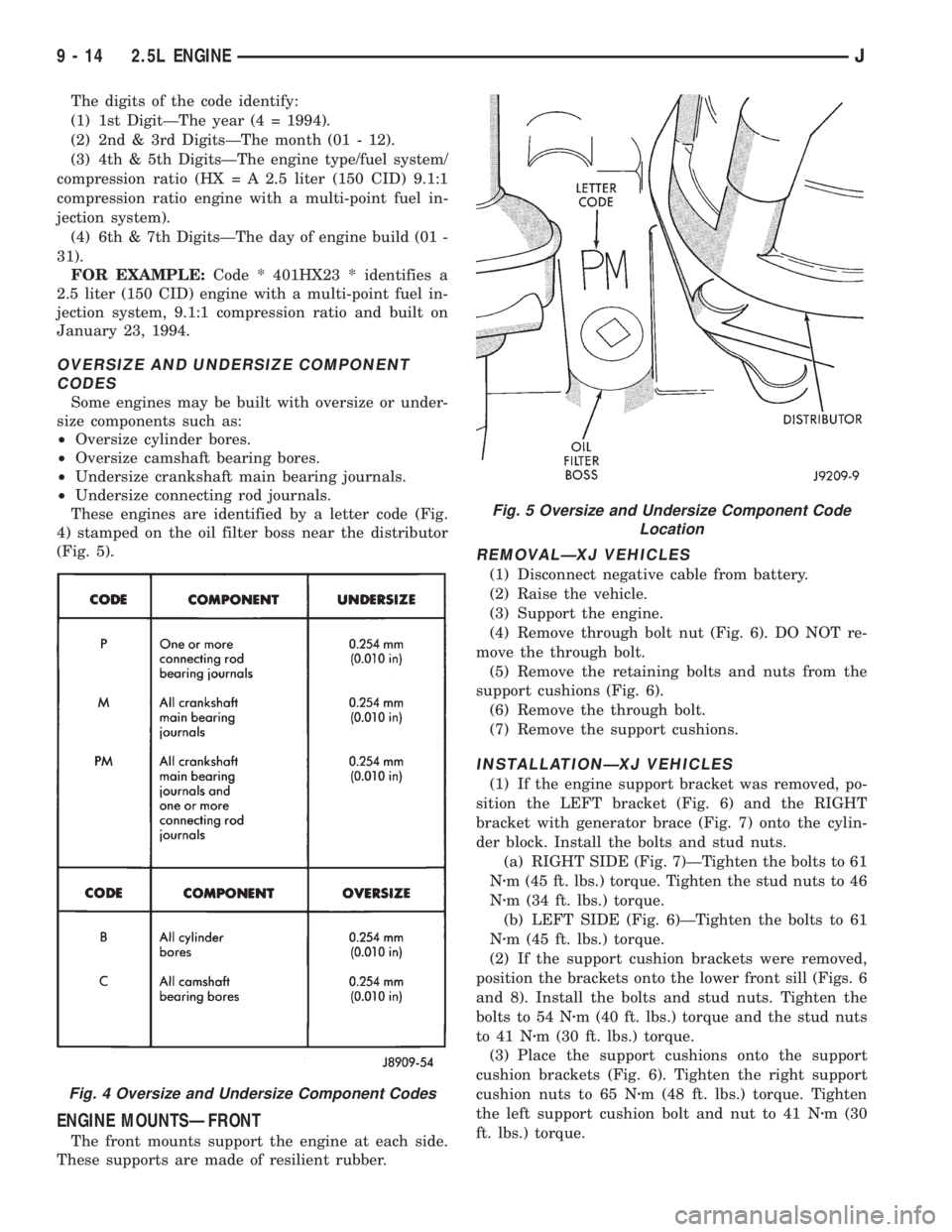
OVERSIZE AND UNDERSIZE COMPONENT
CODES
Some engines may be built with oversize or under-
size components such as:
²Oversize cylinder bores.
²Oversize camshaft bearing bores.
²Undersize crankshaft main bearing journals.
²Undersize connecting rod journals.
These engines are identified by a letter code (Fig.
4) stamped on the oil filter boss near the distributor
(Fig. 5).
ENGINE MOUNTSÐFRONT
The front mounts support the engine at each side.
These supports are made of resilient rubber.
REMOVALÐXJ VEHICLES
(1) Disconnect negative cable from battery.
(2) Raise the vehicle.
(3) Support the engine.
(4) Remove through bolt nut (Fig. 6). DO NOT re-
move the through bolt.
(5) Remove the retaining bolts and nuts from the
support cushions (Fig. 6).
(6) Remove the through bolt.
(7) Remove the support cushions.
INSTALLATIONÐXJ VEHICLES
(1) If the engine support bracket was removed, po-
sition the LEFT bracket (Fig. 6) and the RIGHT
bracket with generator brace (Fig. 7) onto the cylin-
der block. Install the bolts and stud nuts.
(a) RIGHT SIDE (Fig. 7)ÐTighten the bolts to 61
Nzm (45 ft. lbs.) torque. Tighten the stud nuts to 46
Nzm (34 ft. lbs.) torque.
(b) LEFT SIDE (Fig. 6)ÐTighten the bolts to 61
Nzm (45 ft. lbs.) torque.
(2) If the support cushion brackets were removed,
position the brackets onto the lower front sill (Figs. 6
and 8). Install the bolts and stud nuts. Tighten the
bolts to 54 Nzm (40 ft. lbs.) torque and the stud nuts
to 41 Nzm (30 ft. lbs.) torque.
(3) Place the support cushions onto the support
cushion brackets (Fig. 6). Tighten the right support
cushion nuts to 65 Nzm (48 ft. lbs.) torque. Tighten
the left support cushion bolt and nut to 41 Nzm (30
ft. lbs.) torque.
Fig. 4 Oversize and Undersize Component Codes
Fig. 5 Oversize and Undersize Component Code
Location
9 - 14 2.5L ENGINEJ
Page 1110 of 2198
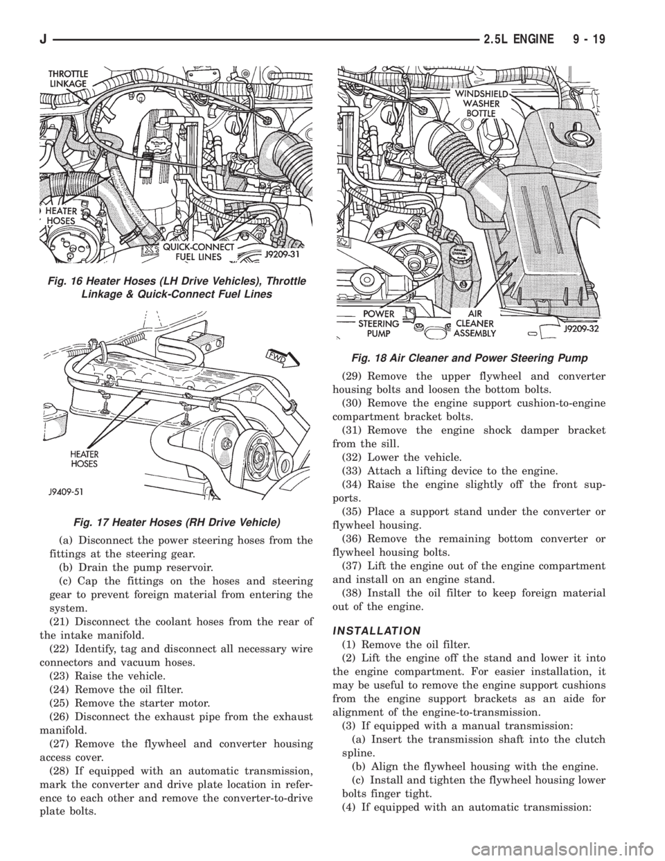
(a) Disconnect the power steering hoses from the
fittings at the steering gear.
(b) Drain the pump reservoir.
(c) Cap the fittings on the hoses and steering
gear to prevent foreign material from entering the
system.
(21) Disconnect the coolant hoses from the rear of
the intake manifold.
(22) Identify, tag and disconnect all necessary wire
connectors and vacuum hoses.
(23) Raise the vehicle.
(24) Remove the oil filter.
(25) Remove the starter motor.
(26) Disconnect the exhaust pipe from the exhaust
manifold.
(27) Remove the flywheel and converter housing
access cover.
(28) If equipped with an automatic transmission,
mark the converter and drive plate location in refer-
ence to each other and remove the converter-to-drive
plate bolts.(29) Remove the upper flywheel and converter
housing bolts and loosen the bottom bolts.
(30) Remove the engine support cushion-to-engine
compartment bracket bolts.
(31) Remove the engine shock damper bracket
from the sill.
(32) Lower the vehicle.
(33) Attach a lifting device to the engine.
(34) Raise the engine slightly off the front sup-
ports.
(35) Place a support stand under the converter or
flywheel housing.
(36) Remove the remaining bottom converter or
flywheel housing bolts.
(37) Lift the engine out of the engine compartment
and install on an engine stand.
(38) Install the oil filter to keep foreign material
out of the engine.
INSTALLATION
(1) Remove the oil filter.
(2) Lift the engine off the stand and lower it into
the engine compartment. For easier installation, it
may be useful to remove the engine support cushions
from the engine support brackets as an aide for
alignment of the engine-to-transmission.
(3) If equipped with a manual transmission:
(a) Insert the transmission shaft into the clutch
spline.
(b) Align the flywheel housing with the engine.
(c) Install and tighten the flywheel housing lower
bolts finger tight.
(4) If equipped with an automatic transmission:
Fig. 16 Heater Hoses (LH Drive Vehicles), Throttle
Linkage & Quick-Connect Fuel Lines
Fig. 17 Heater Hoses (RH Drive Vehicle)
Fig. 18 Air Cleaner and Power Steering Pump
J2.5L ENGINE 9 - 19
Page 1273 of 2198
MULTI-PORT FUEL INJECTION (MFI)ÐCOMPONENT REMOVAL/INSTALLATION
INDEX
page page
Accelerator Pedal and Throttle Cable........... 58
Air Cleaner Element....................... 59
Air Cleaner Housing....................... 58
Air Conditioning (A/C) Clutch Relay............ 58
Automatic Shutdown (ASD) Relay............. 59
Brake Switch............................ 59
Camshaft Position Sensor................... 60
Crankshaft Position Sensor.................. 60
Engine Coolant Temperature Sensor........... 60
Fuel Filter............................... 60
Fuel Injector............................. 60
Fuel Pressure Regulator.................... 61
Fuel Pump Module........................ 61
Fuel Pump Relay......................... 61
Fuel Rail Assembly........................ 62
Fuel System Pressure Release Procedure....... 62
Fuel Tank Pressure Relief/Rollover Valve........ 62Fuel Tanks.............................. 62
Fuel Tubes/Lines/Hoses and Clamps........... 62
Idle Air Control (IAC) Motor.................. 62
Ignition Coil............................. 62
Intake Manifold........................... 63
Intake Manifold Air Temperature Sensor......... 60
Manifold Absolute Pressure (Map) Sensor....... 63
Oxygen (O2S) Sensor...................... 63
Park Neutral Switch....................... 63
Power Steering Pressure SwitchÐ2.5L
Engine Only............................ 63
Powertrain Control Module (PCM)............. 64
Quick-Connect Fittings..................... 64
Throttle Body............................ 64
Throttle Position Sensor (TPS)............... 65
Torque Converter Clutch Relay............... 65
Vehicle Speed Sensor...................... 66
ACCELERATOR PEDAL AND THROTTLE CABLE
Refer to the Accelerator Pedal and Throttle Cable
section of this group for removal/installation proce-
dures.
AIR CONDITIONING (A/C) CLUTCH RELAY
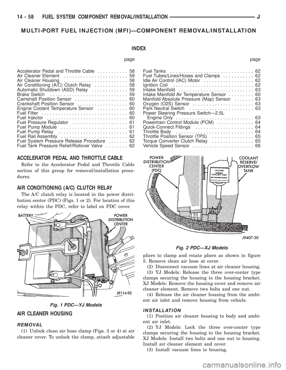
The A/C clutch relay is located in the power distri-
bution center (PDC) (Figs. 1 or 2). For location of this
relay within the PDC, refer to label on PDC cover.
AIR CLEANER HOUSING
REMOVAL
(1) Unlock clean air hose clamp (Figs. 3 or 4) at air
cleaner cover. To unlock the clamp, attach adjustablepliers to clamp and rotate pliers as shown in figure
5. Remove clean air hose at cover.
(2) Disconnect vacuum lines at air cleaner housing.
(3) YJ Models: Release the three over-center type
clamps securing the housing to the housing bracket.
XJ Models: Remove the housing cover and remove air
cleaner element. Remove two bolts and one nut.
(4) Release the air cleaner housing from the ambi-
ent air inlet and remove housing from vehicle.
INSTALLATION
(1) Position air cleaner housing to body and ambi-
ent air inlet.
(2) YJ Models: Lock the three over-center type
clamps securing the housing to the housing bracket.
XJ Models: Install two bolts and one nut to housing.
Install air cleaner element and cover.
(3) Install vacuum lines to housing.
Fig. 1 PDCÐYJ Models
Fig. 2 PDCÐXJ Models
14 - 58 FUEL SYSTEM COMPONENT REMOVAL/INSTALLATIONJ
Page 1275 of 2198
CAMSHAFT POSITION SENSOR
For removal/installation procedures, refer to Group
8D, Ignition System. See Camshaft Position Sensor.
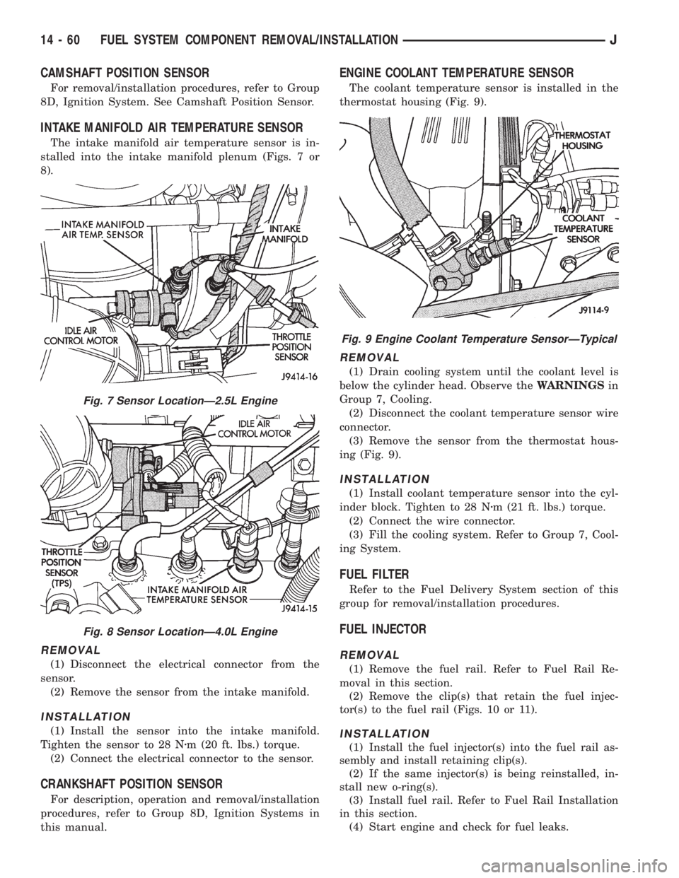
INTAKE MANIFOLD AIR TEMPERATURE SENSOR
The intake manifold air temperature sensor is in-
stalled into the intake manifold plenum (Figs. 7 or
8).
REMOVAL
(1) Disconnect the electrical connector from the
sensor.
(2) Remove the sensor from the intake manifold.
INSTALLATION
(1) Install the sensor into the intake manifold.
Tighten the sensor to 28 Nzm (20 ft. lbs.) torque.
(2) Connect the electrical connector to the sensor.
CRANKSHAFT POSITION SENSOR
For description, operation and removal/installation
procedures, refer to Group 8D, Ignition Systems in
this manual.
ENGINE COOLANT TEMPERATURE SENSOR
The coolant temperature sensor is installed in the
thermostat housing (Fig. 9).
REMOVAL
(1) Drain cooling system until the coolant level is
below the cylinder head. Observe theWARNINGSin
Group 7, Cooling.
(2) Disconnect the coolant temperature sensor wire
connector.
(3) Remove the sensor from the thermostat hous-
ing (Fig. 9).
INSTALLATION
(1) Install coolant temperature sensor into the cyl-
inder block. Tighten to 28 Nzm (21 ft. lbs.) torque.
(2) Connect the wire connector.
(3) Fill the cooling system. Refer to Group 7, Cool-
ing System.
FUEL FILTER
Refer to the Fuel Delivery System section of this
group for removal/installation procedures.
FUEL INJECTOR
REMOVAL
(1) Remove the fuel rail. Refer to Fuel Rail Re-
moval in this section.
(2) Remove the clip(s) that retain the fuel injec-
tor(s) to the fuel rail (Figs. 10 or 11).
INSTALLATION
(1) Install the fuel injector(s) into the fuel rail as-
sembly and install retaining clip(s).
(2) If the same injector(s) is being reinstalled, in-
stall new o-ring(s).
(3) Install fuel rail. Refer to Fuel Rail Installation
in this section.
(4) Start engine and check for fuel leaks.
Fig. 7 Sensor LocationÐ2.5L Engine
Fig. 8 Sensor LocationÐ4.0L Engine
Fig. 9 Engine Coolant Temperature SensorÐTypical
14 - 60 FUEL SYSTEM COMPONENT REMOVAL/INSTALLATIONJ
Page 1966 of 2198
CLUSTER GROUND; INSTRUMENT
CLUSTER (XJ-RHD)................8W-40-2
CLUSTER ILLUMINATION LAMPS . . 8E-16,8E-26,
8E-34,8E-4
CLUSTER, INSTRUMENT; INSTRUMENT
CLUSTER (XJ).....................8W-40-1
CLUSTER, INSTRUMENT; INSTRUMENT
CLUSTER (XJ-RHD)................8W-40-1
CLUSTER, INSTRUMENT; INSTRUMENT
CLUSTER (YJ).....................8W-40-1
CLUSTER (LHD), HIGH-LINE GAUGE.......8E-9
CLUSTER (LHD), TELL-TALE............8E-10
CLUSTER, LOW-LINE GAUGE............8E-8
CLUSTER, MAIN.....................8E-30
CLUSTERS, INSTRUMENT..........8E-24,8E-1
CLUTCH, A/C COMPRESSOR............24-15
CLUTCH AND BRAKE PACK
REQUIREMENTS, AW-4...............21-341
CLUTCH AND BRAKE PEDAL BUSHINGS . . . 0-22
CLUTCH ASSEMBLY, COMPRESSOR......24-20
CLUTCH COMPONENT LUBRICATION......6-10
CLUTCH COMPONENTS..................6-1
CLUTCH, COMPRESSOR...............24-16
CLUTCH CONTAMINATION...............6-3
CLUTCH COVER AND DISC
INSTALLATION........................6-10
CLUTCH COVER AND DISC REMOVAL.....6-10
CLUTCH COVER AND DISC RUNOUT.......6-3
CLUTCH DIAGNOSIS.....................6-3
CLUTCH DISC AND PLATE THICKNESS,
AW-4 .............................21-338
CLUTCH FLUID LEVEL..................6-14
CLUTCH HOUSING MISALIGNMENT........6-4
CLUTCH HOUSING REPLACEMENT........6-13
CLUTCH HYDRAULIC LINKAGE
INSTALLATION........................6-14
CLUTCH HYDRAULIC LINKAGE REMOVAL . . 6-13
CLUTCH INSPECTION, TORQUE
CONVERTER STATOR................21-199
CLUTCH LINKAGE FLUID.................6-1
CLUTCH MASTER CYLINDER............0-22
CLUTCH MISALIGNMENT................6-3
CLUTCH OPERATION....................6-2
CLUTCH OVERHAUL, DIRECT..........21-228
CLUTCH OVERHAUL, OVERDRIVE
PLANETARY GEAR...................21-218
CLUTCH OVERHAUL, SUN GEAR AND
NO. 1 ONE-WAY....................21-238
CLUTCH PEDAL INSTALLATION..........6-15
CLUTCH PEDAL REMOVAL..............6-15
CLUTCH RELAY, A/C COMPRESSOR . 24-15,24-16
CLUTCH RELAY, AIR CONDITIONING
(A/C)..............................14-58
CLUTCH RELAY TEST, TORQUE
CONVERTER........................14-48
CLUTCH RELAY, TORQUE CONVERTER....14-65
CLUTCH RELAYÐPCM OUTPUT, AIR
CONDITIONING (A/C)..................14-26
CLUTCH RELAYÐPCM OUTPUT, TORQUE
CONVERTER........................14-29
CLUTCH SAFETY PRECAUTIONS..........6-10
CLUTCH SERVICE
.....................6-10
CLUTCH SWITCH, FIN SENSING
CYCLING
......................24-15,24-31
CLUTCH (TCC) SOLENOID AND RELAY,
TORQUE CONVERTER; FUEL/IGNITION
(XJ)
.............................8W-30-4
CLUTCH (TCC) SOLENOID AND RELAY,
TORQUE CONVERTER; TRANSMISSION
CONTROLS (YJ)
...................8W-31-1
CLUTCH (TCC) SOLENOID AND
RELAYÐ2.5L ENGINE ONLY, TORQUE
CONVERTER; TRANSMISSION
CONTROLS (XJ)
...................8W-31-1
CLUTCHÐLOW-REVERSE DRUMÐREAR
SUPPORT OVERHAUL, OVERRUNNING
. . . 21-125
CODE DECODING, VEHICLE
...........Intro.-5
CODE DESIGNATIONS, VEHICLE
........Intro.-1
CODE (DTC), DIAGNOSTIC TROUBLE
.....14-54
CODE, GENERATOR DIAGNOSTIC
TROUBLE
...........................8A-22
CODE IDENTIFICATION, WIRE; WIRING
DIAGRAMSÐGENERAL INFORMATION
(XJ)
...............................8W-1
CODE PLATE, VEHICLE
...............Intro.-4
CODE, SPEED CONTROL DIAGNOSTIC
TROUBLE
...........................8H-5CODES AND DIMENSIONS,
DESIGNATIONS, LABELS/PLATES.......Intro.-1
COIL, EVAPORATOR..................24-30
COIL, IGNITION; FUEL SYSTEM.........14-62
COIL, IGNITION; FUEL/IGNITION (XJ) . . . 8W-30-2
COIL, IGNITION; FUEL/IGNITION (YJ) . . . 8W-30-2
COIL, IGNITION; IGNITION SYSTEMS....8D-22,
8D-4,8D-9
COIL, IGNITION; FUEL/IGNITION
(XJ-RHD).........................8W-30-2
COIL RESISTANCE, IGNITION............8D-9
COIL SPRING........................2-14
COILÐPCM OUTPUT, IGNITION.........14-28
COLD CRANKING SPECIFICATIONS, 2.5L
STARTING SYSTEM...................8A-23
COLD CRANKING SPECIFICATIONS, 4.0L
STARTING SYSTEM...................8A-23
COLUMN ASSEMBLY REPLACEMENT.....19-52
COLUMN COMPONENT SERVICE........19-54
COLUMN GENERAL SERVICEÐXJ,
STEERING..........................19-47
COLUMN, NON-TILT STEERING..........19-60
COLUMN REPLACEMENT..............19-58
COLUMN, TILT STEERING..............19-66
COLUMNÐXJ, STEERING..............19-78
COLUMNÐYJ, STEERING.........19-58,19-78
COMBINATION BUZZER; INTERIOR
LIGHTING (YJ)....................8W-44-1
COMBINATION FLASHER; TURN SIGNALS
(XJ).............................8W-52-1
COMBINATION VALVE..................5-34
COMBINATION VALVE INSTALLATION
(WITH ABS), MASTER CYLINDER.........5-20
COMBINATION VALVE REMOVAL (WITH
ABS), MASTER CYLINDER..............5-17
COMBINATION VALVE REPLACEMENT
(NON-ABS)..........................5-16
COMBUSTION PRESSURE LEAKAGE
TEST, CYLINDER.......................9-6
COMBUSTION PRESSURE LEAKAGE
TEST DIAGNOSIS, CYLINDER.............9-7
COMFORT SWITCH, TRANSMISSION;
TRANSMISSION CONTROLS (XJ-RHD) . . 8W-31-1
COMPASS...........................8C-1
COMPASS/DISPLAY SELF-DIAGNOSTIC
TEST...............................8C-2
COMPASS/THERMOMETER DIAGNOSIS....8C-4
COMPENSATION, CALIPER OPERATION
AND WEAR..........................5-45
COMPONENTSÐYJ, EVAPORATIVE
HOUSING............................24-6
COMPONENTSÐYJ, INSTRUMENT
PANEL............................23-152
COMPONENTSÐYJ VEHICLES, BODY....23-102
COMPRESSION PRESSURE TEST,
CYLINDER............................9-5
COMPRESSOR.......................24-19
COMPRESSOR, A/C; AIR CONDITIONING/
HEATER (YJ)......................8W-42-2
COMPRESSOR, AIR-CONDITIONER........0-21
COMPRESSOR CLUTCH...............24-16
COMPRESSOR CLUTCH, A/C............24-15
COMPRESSOR CLUTCH ASSEMBLY......24-20
COMPRESSOR CLUTCH RELAY, A/C . 24-15,24-16
COMPRESSOR SERVICE...............24-19
CONDENSER, A/C
....................24-34
CONDENSER FILTER DRIERÐ2.5L
ENGINES
...........................24-27
CONDENSERÐ4.0L ENGINES
...........24-28
CONDITION, CHECKING FLUID LEVEL
....21-182
CONDITIONING (A/C) CLUTCH RELAY,
AIR
...............................14-58
CONDITIONING (A/C) CLUTCH
RELAYÐPCM OUTPUT, AIR
............14-26
CONDITIONING (A/C) CONTROLSÐPCM
INPUT, AIR
.........................14-21
CONDITIONING, AIR
..................24-37
CONDITIONING CONTROLSÐXJ
VEHICLES, AIR
......................24-15
CONDITIONING CONTROLSÐYJ
VEHICLES, AIR
......................24-16
CONDITIONING, HEATER AND AIR; AIR
CONDITIONING/HEATER (YJ)
.........8W-42-2
CONDITIONING OPERATION, AIR; AIR
CONDITIONING/HEATER (XJ)
.........8W-42-2
CONDITIONING OPERATION, AIR; AIR
CONDITIONING/HEATER (XJ-RHD)
.....8W-42-2CONDITIONING PERFORMANCE TESTS,
AIR ...............................24-12
CONDITIONING SCHEMATICÐXJ, AIR.....24-5
CONDITIONING TEST PROCEDURES,
HEATING AND AIR....................24-15
CONDITIONS, NORMAL OPERATING........5-3
CONNECTING ROD BEARING FITTING
CHART..........................9-41,9-83
CONNECTING RODS, PISTONS.......9-39,9-81
CONNECTIONS, INTERMITTENT AND
POOR; WIRING DIAGRAMSÐGENERAL
INFORMATION (XJ)...................8W-4
CONNECTIONS, RADIO ILLUMINATION
RELAY..............................8F-4
CONNECTIONS, STARTER RELAY........8A-15
CONNECTOR, ABS DIAGNOSTIC.......5-35,5-3
CONNECTOR AND TERMINAL
REPLACEMENT; WIRING DIAGRAMSÐ
GENERAL INFORMATION (XJ)...........8W-7
CONNECTOR, DATA LINK; ANTI-LOCK
BRAKES (XJ)......................8W-32-2
CONNECTOR, DATA LINK; ANTI-LOCK
BRAKES (XJ-RHD).................8W-32-2
CONNECTOR, DATA LINK; ANTI-LOCK
BRAKES (YJ)......................8W-32-2
CONNECTOR, DATA LINK; FUEL/IGNITION
(XJ).............................8W-30-5
CONNECTOR, DATA LINK; FUEL/IGNITION
(YJ).............................8W-30-5
CONNECTOR, DATA LINK;
TRANSMISSION CONTROLS (XJ-RHD) . . 8W-31-1
CONNECTOR, DATA LINK; FUEL/IGNITION
(XJ-RHD)..........................8W-30-4
CONNECTOR LOCATIONS; CONNECTOR
LOCATIONS (XJ)...................8W-90-1
CONNECTOR LOCATIONS; CONNECTOR
LOCATIONS (XJ-RHD)...............8W-90-1
CONNECTOR LOCATIONS; CONNECTOR
LOCATIONS (YJ)...................8W-90-1
CONNECTOR LOCATIONS; CONNECTOR
PIN OUTS (XJ)....................8W-80-1
CONNECTOR LOCATIONS; CONNECTOR
PIN OUTS (XJ-RHD)................8W-80-1
CONNECTOR LOCATIONS; CONNECTOR
PIN OUTS (YJ)....................8W-80-1
CONNECTOR LOCATIONS; WIRING
DIAGRAMS (XJ)......................8W-1
CONNECTOR LOCATIONS; WIRING
DIAGRAMS (XJ-RHD)..................8W-1
CONNECTOR LOCATIONS; WIRING
DIAGRAMS (YJ)......................8W-1
CONNECTOR, POWERTRAIN CONTROL
MODULE (PCM) 60-WAY...............14-40
CONNECTOR REPLACEMENT; WIRING
DIAGRAMSÐGENERAL INFORMATION
(XJ)...............................8W-6
CONNECTORÐPCM INPUT, DATA LINK . . . 14-22
CONNECTORÐPCM OUTPUT, DATA LINK . . 14-27
CONNECTORS; WIRING DIAGRAMSÐ
GENERAL INFORMATION (XJ)...........8W-2
CONNECTORS (RHD), CLUSTER.........8E-11
CONNECTORS, TERMINAL/CONNECTOR
REPAIRÐMOLEX; WIRING
DIAGRAMSÐGENERAL INFORMATION
(XJ)...............................8W-6
CONSOLE, OVERHEAD; OVERHEAD
CONSOLE (XJ)....................8W-49-1
CONSOLE, OVERHEAD; OVERHEAD
CONSOLE (XJ-RHD)................8W-49-1
CONSOLE REMOVE/INSTALL, OVERHEAD . . . 8C-6
CONSOLE SHIFT, DISASSEMBLYÐ
COLUMN OR........................19-60
CONSOLEÐXJ, FULL FLOOR...........23-95
CONSOLEÐXJ, MINI-FLOOR............23-94
CONSOLEÐXJ, OVERHEAD; BODY
COMPONENTSÐXJ VEHICLES..........23-93
CONSOLEÐXJ, OVERHEAD; LAMPS......8L-17
CONSOLESÐYJ, FLOOR..............23-155
CONTACT PATTERN ANALYSIS,
BACKLASH; FRONT SUSPENSION AND
AXLE...............................2-45
CONTACT PATTERN ANALYSIS,
BACKLASH; REAR SUSPENSION AND
AXLES
..............................3-27
CONTACT/CLOCKSPRING, HORN
.........8G-4
CONTAMINATED BRAKELINING
............5-7
CONTAMINATION, BRAKE FLUID
.......5-10,5-7
CONTAMINATION, CLUTCH
...............6-3
JINDEX 5
Description Group-Page Description Group-Page Description Group-Page