steering wheel JEEP CHEROKEE 1995 Service Repair Manual
[x] Cancel search | Manufacturer: JEEP, Model Year: 1995, Model line: CHEROKEE, Model: JEEP CHEROKEE 1995Pages: 2198, PDF Size: 82.83 MB
Page 5 of 2198
MAINTENANCE SCHEDULES
INTRODUCTION
There are two maintenance schedules that show
proper service intervals for Jeep Cherokee and Jeep
Wrangler vehicles. Use the schedule that best de-
scribes the conditions the vehicle is operated under.
When mileage and time is listed, follow the interval
that occurs first.
ScheduleÐAlists all the scheduled maintenance
to be performed under normal operating conditions.
ScheduleÐBis a schedule for vehicles that are
usually operated under one or more of the following
conditions.
²Frequent short trip driving less than 5 miles (8
km).
²Frequent driving in dusty conditions.
²Trailer towing or heavy load hauling.
²Frequent long periods of engine idling.
²Sustained high speed operation.
²Desert operation.
²Frequent starting and stopping.
²Cold climate operation.
²Off road driving.
²Commercial service.
²Snow plow operation.
²More than half of vehicle operation occurs in
heavy city traffic during hot weather (above 90É F).
AT EACH STOP FOR GASOLINE
²Check engine oil level and add as required.
²Check windshield washer solvent and add as re-
quired.
ONCE A MONTH
²Check tire pressure and look for unusual tire wear
or damage.
²Check fluid levels of coolant reservoir, brake mas-
ter cylinder, power steering and transmission. Add
fluid as required.
²Check all lights and other electrical items for cor-
rect operation.
²Inspect battery and clean and tighten terminals as
required.
²Check rubber seals on each side of the radiator for
proper fit.
AT EACH OIL CHANGE
²Inspect exhaust system.
²Inspect brake hoses.
²Rotate the tires at each oil change interval shown
on ScheduleÐA: (7,500 Miles) or every other interval
shown on ScheduleÐB: (6,000 Miles).
²Check engine coolant level, hoses, and clamps.
²Lubricate 4x4 steering linkage.
²Lubricate propeller shaft universal joints and slip
spline, if equipped.After completion of off-road (4WD) operation, the
underside of the vehicle should be thoroughly in-
spected. Examine threaded fasteners for looseness.
HARSH SURFACE ENVIRONMENTS
After vehicle operation in a harsh surface environ-
ment, the following components should be inspected
and cleaned as soon as possible:
²Brake drums.
²Brake linings.
²Front wheel bearings (2WD vehicles only).
²Axle coupling joints.
This will prevent wear and/or unpredictable brake
action.
EMISSION CONTROL SYSTEM MAINTENANCE
The schedule emission maintenance listed inbold
typeon the following schedules, must be done at the
mileage specified to assure the continued proper
functioning of the emission control system. These,
and all other maintenance services included in this
manual, should be done to provide the best vehicle
performance and reliability. More frequent mainte-
nance may be needed for vehicles in severe operating
conditions such as dusty areas and very short trip
driving.
SCHEDULEÐA
7,500 MILES (12 000 KM) OR AT 6 MONTHS
²Change engine oil.
²Replace engine oil filter.
²Lubricate steering linkage (4x4).
15,000 MILES (24 000 KM) OR AT 12 MONTHS
²Change engine oil.
²Replace engine oil filter.
²Lubricate steering linkage.
22,500 MILES (36 000 KM) OR AT 18 MONTHS
²Change engine oil.
²Replace engine oil filter.
²Lubricate steering linkage (4x4).
²Inspect brake linings.
30,000 MILES (48 000 KM) OR AT 24 MONTHS
²Replace air cleaner element.
²Replace spark plugs.
²Adjust belt tension on non-automatic tensioning
drive belts.
²Change engine oil.
²Replace engine oil filter.
²Lubricate steering linkage.
²Drain and refill automatic transmission.
²Drain and refill transfer case.
0 - 4 LUBRICATION AND MAINTENANCEJ
Page 7 of 2198
SCHEDULEÐB
3,000 MILES (4 800KM)
²Change engine oil.
²Replace engine oil filter.
6,000 MILES (9 600KM)
²Change engine oil.
²Replace engine oil filter.
²Lubricate steering linkage (4x4).
9,000 MILES (14 400KM)
²Change engine oil.
²Replace engine oil filter.
12,000 MILES (19 200KM)
²Change engine oil.
²Replace engine oil filter.
²Drain and refill automatic transmission.
²Change front and rear axle fluid.*
²Lubricate steering linkage (4x4).
²Inspect brake linings.
15,000 MILES (24 000KM)
²Change engine oil.
²Replace engine oil filter.
²Lubricate steering linkage (4x2).
²Inspect air cleaner element, replace as necessary.
18,000 MILES (29 000KM)
²Change engine oil.
²Replace engine oil filter.
²Drain and refill Manual transmission fluid.
²Lubricate steering linkage (4x4).
21,000 MILES (34 000KM)
²Change engine oil.
²Replace engine oil filter.
24,000 MILES (38 000KM)
²Change engine oil.
²Replace engine oil filter.
²Lubricate steering linkage (4x4).
²Drain and refill automatic transmission.
²Change front and rear axle fluid.*
²Inspect brake linings.
²Inspect front wheel bearings, Clean and repack if
required (4x2).
27,000 MILES (43 000KM)
²Change engine oil.
²Replace engine oil filter.
30,000 MILES (48 000KM)
²Change engine oil.
²Replace engine oil filter.
²Lubricate steering linkage joints.
²Replace spark plugs.
²Replace air cleaner element.²Adjust drive belts.
²Drain and refill transfer case fluid.
33,000 MILES (53 000KM)
²Change engine oil.
²Replace engine oil filter.
36,000 MILES (58 000KM)
²Change engine oil.
²Replace engine oil filter.
²Lubricate steering linkage (4x4).
²Drain and refill automatic transmission.
²Drain and refill manual transmission fluid.
²Change front and rear axle fluid.*
²Inspect brake linings.
39,000 MILES (62 000KM)
²Change engine oil.
²Replace engine oil filter.
42,000 MILES (67 000KM)
²Change engine oil.
²Replace engine oil filter.
²Lubricate steering linkage (4x4).
45,000 MILES (72 000KM)
²Change engine oil.
²Replace engine oil filter.
²Lubricate steering linkage (4x2).
²Inspect air cleaner element, replace as necessary.
48,000 MILES (77 000KM)
²Change engine oil.
²Replace engine oil filter.
²Lubricate steering linkage (4x4).
²Drain and refill automatic transmission.
²Change front and rear axle fluid.*
²Inspect brake linings.
51,000 MILES (82 000KM)
²Change engine oil.
²Replace engine oil filter.
²Flush and replace engine coolant.
54,000 MILES (86 400KM)
²Change engine oil.
²Replace engine oil filter.
²Lubricate steering linkage (4x4).
²Drain and refill Manual transmission fluid.
57,000 MILES (91 000KM)
²Change engine oil.
²Replace engine oil filter.
60,000 MILES (96 000KM)
²Change engine oil.
²Replace engine oil filter.
²Lubricate steering linkage joints.
²Replace spark plugs.
0 - 6 LUBRICATION AND MAINTENANCEJ
Page 11 of 2198
CAUTION: Do not crank starter motor on disabled
vehicle for more than 15 seconds, starter will over-
heat and could fail.
(6) Allow battery in disabled vehicle to charge to at
least 12.4 volts (75%charge) before attempting to
start engine. If engine does not start within 15 sec-
onds, stop cranking engine and allow starter to cool
(15 min.), before cranking again.
DISCONNECT CABLE CLAMPS AS FOLLOWS:
²Disconnect BLACK cable clamp from engine
ground on disabled vehicle.
²When using a Booster vehicle, disconnect BLACK
cable clamp from battery negative terminal. Discon-
nect RED cable clamp from battery positive terminal.
²Disconnect RED cable clamp from battery positive
terminal on disabled vehicle.
PORTABLE STARTING UNIT
There are many types of portable starting units
available for starting engines. Follow the manufac-
turer's instructions and observe the listed precau-
tions when involved in any engine starting
procedure.
HOISTING RECOMMENDATIONS
Refer to the Owner's Manual for emergency vehicle
lifting procedures.
FLOOR JACK
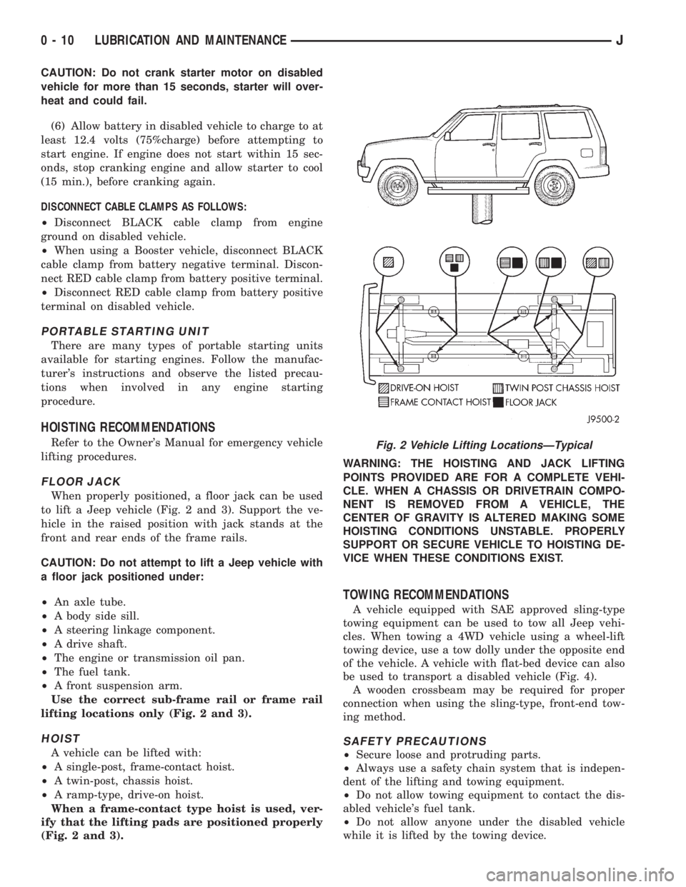
When properly positioned, a floor jack can be used
to lift a Jeep vehicle (Fig. 2 and 3). Support the ve-
hicle in the raised position with jack stands at the
front and rear ends of the frame rails.
CAUTION: Do not attempt to lift a Jeep vehicle with
a floor jack positioned under:
²An axle tube.
²A body side sill.
²A steering linkage component.
²A drive shaft.
²The engine or transmission oil pan.
²The fuel tank.
²A front suspension arm.
Use the correct sub-frame rail or frame rail
lifting locations only (Fig. 2 and 3).
HOIST
A vehicle can be lifted with:
²A single-post, frame-contact hoist.
²A twin-post, chassis hoist.
²A ramp-type, drive-on hoist.
When a frame-contact type hoist is used, ver-
ify that the lifting pads are positioned properly
(Fig. 2 and 3).WARNING: THE HOISTING AND JACK LIFTING
POINTS PROVIDED ARE FOR A COMPLETE VEHI-
CLE. WHEN A CHASSIS OR DRIVETRAIN COMPO-
NENT IS REMOVED FROM A VEHICLE, THE
CENTER OF GRAVITY IS ALTERED MAKING SOME
HOISTING CONDITIONS UNSTABLE. PROPERLY
SUPPORT OR SECURE VEHICLE TO HOISTING DE-
VICE WHEN THESE CONDITIONS EXIST.
TOWING RECOMMENDATIONS
A vehicle equipped with SAE approved sling-type
towing equipment can be used to tow all Jeep vehi-
cles. When towing a 4WD vehicle using a wheel-lift
towing device, use a tow dolly under the opposite end
of the vehicle. A vehicle with flat-bed device can also
be used to transport a disabled vehicle (Fig. 4).
A wooden crossbeam may be required for proper
connection when using the sling-type, front-end tow-
ing method.
SAFETY PRECAUTIONS
²Secure loose and protruding parts.
²Always use a safety chain system that is indepen-
dent of the lifting and towing equipment.
²Do not allow towing equipment to contact the dis-
abled vehicle's fuel tank.
²Do not allow anyone under the disabled vehicle
while it is lifted by the towing device.
Fig. 2 Vehicle Lifting LocationsÐTypical
0 - 10 LUBRICATION AND MAINTENANCEJ
Page 12 of 2198
²Do not allow passengers to ride in a vehicle being
towed.
²Always observe state and local laws regarding tow-
ing regulations.²Do not tow a vehicle in a manner that could jeop-
ardize the safety of the operator, pedestrians or other
motorists.
²Do not attach tow chains, T-hooks, J-hooks, or a
tow sling to a bumper, steering linkage, drive shafts
or a non-reinforced frame hole.
GROUND CLEARANCE AND RAMP ANGLE
GROUND CLEARANCE
CAUTION: If vehicle is towed with wheels removed,
install lug nuts to retain brake drums.
A towed vehicle should be raised until lifted wheels
are a minimum 100 mm (4 in) from the ground. Be
sure there is adequate ground clearance at the oppo-
site end of the vehicle, especially when towing over
rough terrain or steep rises in the road. If necessary,
remove the wheels from the lifted end of the vehicle
and lower the vehicle closer to the ground, to in-
crease the ground clearance at the opposite end of
the vehicle. Install lug nuts on wheel attaching studs
to retain brake drums.
FLAT-BED TOWING RAMP ANGLE
If a vehicle with flat-bed towing equipment is used,
the approach ramp angle should not exceed 15 de-
grees.
TWO-WHEEL-DRIVE VEHICLE TOWINGÐXJ
Chrysler Corporation recommends that a vehicle be
towed with the rear end lifted, whenever possible.
TOWING-REAR END LIFTED (SLING-TYPE)
CAUTION: Do not use steering column lock to se-
cure steering wheel during towing operation.
2WD XJ vehicles can be towed with the front
wheels on the surface for extended distances at
speeds not exceeding 48 km/h (30 mph).
(1) Attach J-hooks around the axle shaft tube out-
board of the shock absorber.
(2) Place the sling crossbar under and forward of
the bumper.
(3) Attach safety chains around the frame rails.
(4) Turn the ignition switch to the OFF position to
unlock the steering wheel.
(5) Secure steering wheel in the straight ahead po-
sition with a clamp device designed for towing.
(6) Verify that steering components are in good
condition.
(7) Shift the transmission to NEUTRAL.
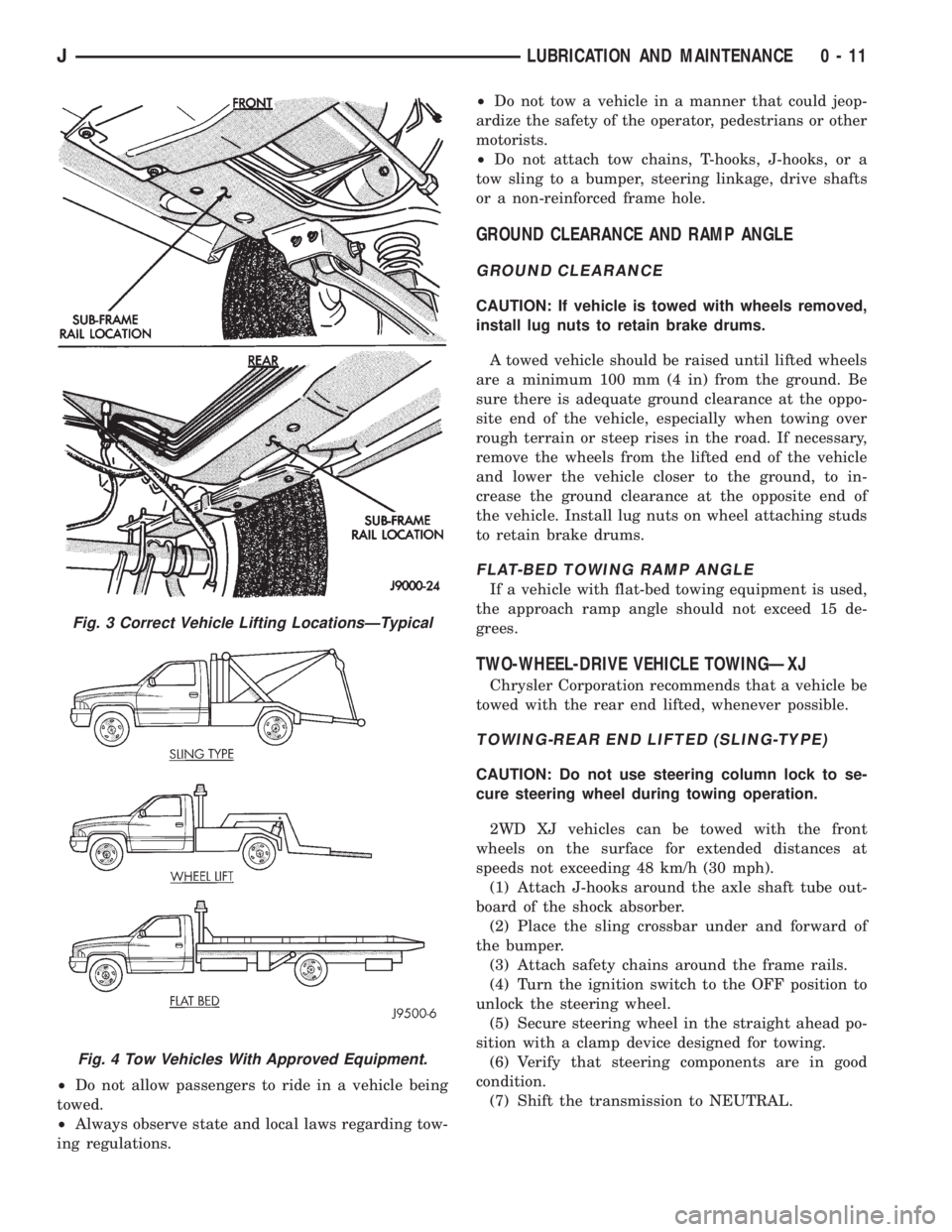
Fig. 3 Correct Vehicle Lifting LocationsÐTypical
Fig. 4 Tow Vehicles With Approved Equipment.
JLUBRICATION AND MAINTENANCE 0 - 11
Page 13 of 2198
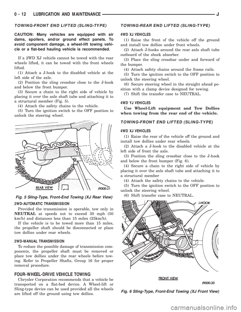
TOWING-FRONT END LIFTED (SLING-TYPE)
CAUTION: Many vehicles are equipped with air
dams, spoilers, and/or ground effect panels. To
avoid component damage, a wheel-lift towing vehi-
cle or a flat-bed hauling vehicle is recommended.
If a 2WD XJ vehicle cannot be towed with the rear
wheels lifted, it can be towed with the front wheels
lifted.
(1) Attach a J-hook to the disabled vehicle at the
left side of the axle.
(2) Position the sling crossbar close to the J-hook
and below the front bumper.
(3) Secure a chain to the right side of vehicle by
placing it over the axle shaft tube and attaching it to
a structural member (Fig. 5).
(4) Attach the safety chains to the vehicle.
(5) Turn the ignition switch to the OFF position to
unlock the steering wheel.
2WD-AUTOMATIC TRANSMISSION
Provided the transmission is operable, tow only in
NEUTRALat speeds not to exceed 30 mph (50
km/h) and distances less than 15 miles (25km/h).
If the vehicle is to be towed more than 15 miles,
the propeller shaft should be disconnected or place
tow dollies under rear wheels.
2WD-MANUAL TRANSMISSION
To reduce the possible damage of transmission com-
ponents, the propeller shaft must be removed or
place tow dollies under the rear wheels before tow-
ing. Refer to Propeller Shafts, Group 16 for proper
removal procedure.
FOUR-WHEEL-DRIVE VEHICLE TOWING
Chrysler Corporation recommends that a vehicle be
transported on a flat-bed device. A Wheel-lift or
Sling-type device can be used provided all the wheels
are lifted off the ground using tow dollies.
TOWING-REAR END LIFTED (SLING-TYPE)
4WD XJ VEHICLES
(1) Raise the front of the vehicle off the ground
and install tow dollies under front wheels.
(2) Attach J-hooks around the rear axle shaft tube
outboard of the shock absorber.
(3) Place the sling crossbar under and forward of
the bumper.
(4) Attach safety chains around the frame rails.
(5) Turn the ignition switch to the OFF position to
unlock the steering wheel.
(6) Secure steering wheel in the straight ahead po-
sition with a clamp device designed for towing.
(7) Shift the transfer case to NEUTRAL.
4WD YJ VEHICLES
Use Wheel-Lift equipment and Tow Dollies
when towing from the rear end of the vehicle.
TOWING-FRONT END LIFTED (SLING-TYPE)
4WD XJ VEHICLES
(1) Raise the rear of the vehicle off the ground and
install tow dollies under rear wheels.
(2) Attach a J-hook to the disabled vehicle at the
left side of front the axle.
(3) Position the sling crossbar close to the J-hook
and below the front bumper (Fig. 6).
(4) Secure a chain to the right side of vehicle by
placing it over the axle shaft tube and attaching it to
a structural member
(4) Attach the safety chains to the vehicle.
(5) Turn the ignition switch to the OFF position to
unlock the steering wheel.
(6) Shift transfer case to NEUTRAL.
Fig. 5 Sling-Type, Front-End Towing (XJ Rear View)
Fig. 6 Sling-Type, Front-End Towing (XJ Front View)
0 - 12 LUBRICATION AND MAINTENANCEJ
Page 14 of 2198
4WD YJ VEHICLES
(1) Raise the rear of the vehicle off the ground and
install tow dollies under rear wheels.
CAUTION: Use tow chains with T-hooks for con-
necting to the disabled vehicle's frame rails. Never
use J-hooks.
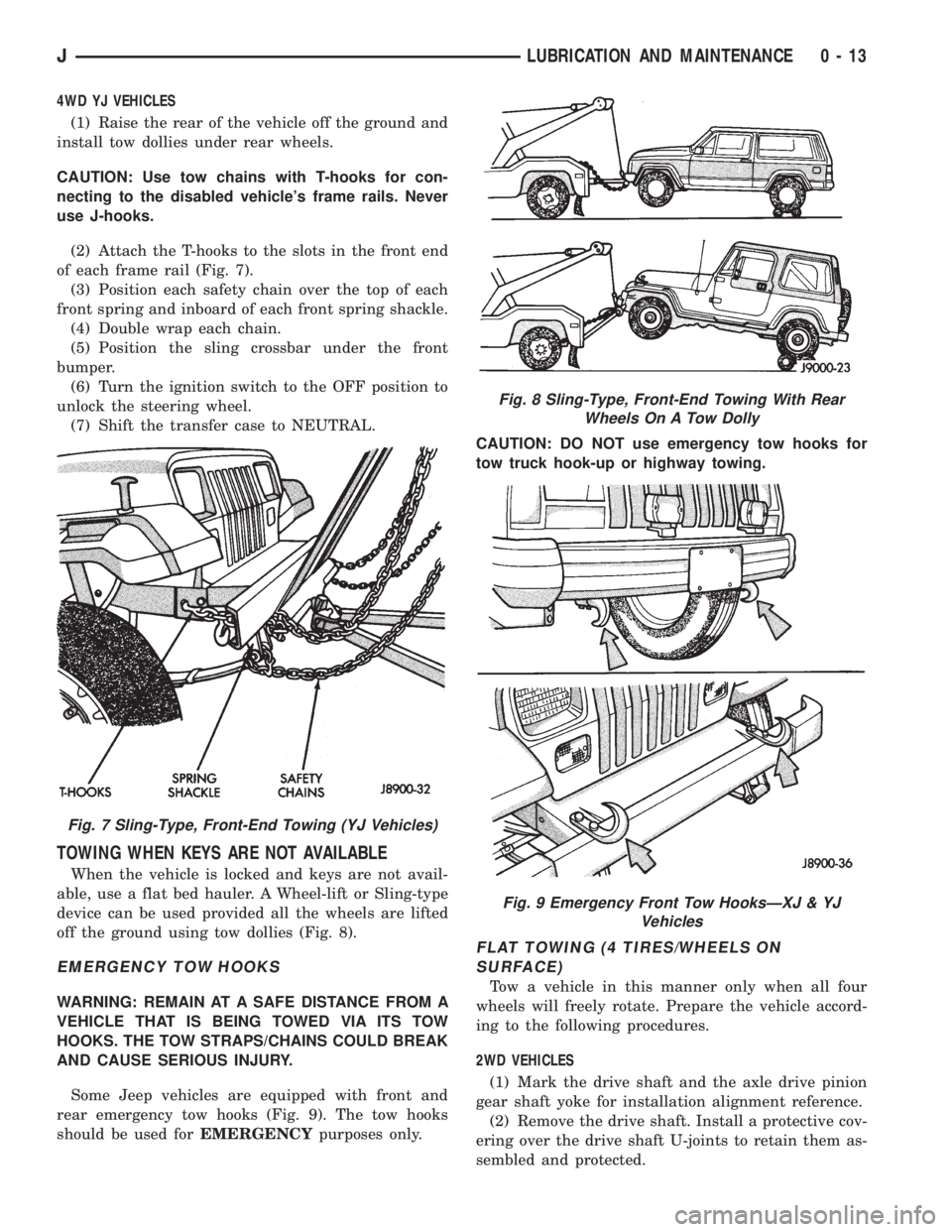
(2) Attach the T-hooks to the slots in the front end
of each frame rail (Fig. 7).
(3) Position each safety chain over the top of each
front spring and inboard of each front spring shackle.
(4) Double wrap each chain.
(5) Position the sling crossbar under the front
bumper.
(6) Turn the ignition switch to the OFF position to
unlock the steering wheel.
(7) Shift the transfer case to NEUTRAL.
TOWING WHEN KEYS ARE NOT AVAILABLE
When the vehicle is locked and keys are not avail-
able, use a flat bed hauler. A Wheel-lift or Sling-type
device can be used provided all the wheels are lifted
off the ground using tow dollies (Fig. 8).
EMERGENCY TOW HOOKS
WARNING: REMAIN AT A SAFE DISTANCE FROM A
VEHICLE THAT IS BEING TOWED VIA ITS TOW
HOOKS. THE TOW STRAPS/CHAINS COULD BREAK
AND CAUSE SERIOUS INJURY.
Some Jeep vehicles are equipped with front and
rear emergency tow hooks (Fig. 9). The tow hooks
should be used forEMERGENCYpurposes only.CAUTION: DO NOT use emergency tow hooks for
tow truck hook-up or highway towing.
FLAT TOWING (4 TIRES/WHEELS ON
SURFACE)
Tow a vehicle in this manner only when all four
wheels will freely rotate. Prepare the vehicle accord-
ing to the following procedures.
2WD VEHICLES
(1) Mark the drive shaft and the axle drive pinion
gear shaft yoke for installation alignment reference.
(2) Remove the drive shaft. Install a protective cov-
ering over the drive shaft U-joints to retain them as-
sembled and protected.
Fig. 7 Sling-Type, Front-End Towing (YJ Vehicles)
Fig. 8 Sling-Type, Front-End Towing With Rear
Wheels On A Tow Dolly
Fig. 9 Emergency Front Tow HooksÐXJ & YJ
Vehicles
JLUBRICATION AND MAINTENANCE 0 - 13
Page 29 of 2198
CHASSIS AND BODY COMPONENTS
INDEX
page page
Body Components........................ 32
Chassis Component and Wheel Bearing
Lubricants............................. 28
Front Wheel Bearings...................... 28
Headlamps.............................. 33
Manual Steering Gear...................... 30Power Brake System....................... 30
Power Steering System..................... 29
Speedometer Cable....................... 33
Steering Linkage.......................... 28
Tires................................... 32
CHASSIS COMPONENT AND WHEEL BEARING
LUBRICANTS
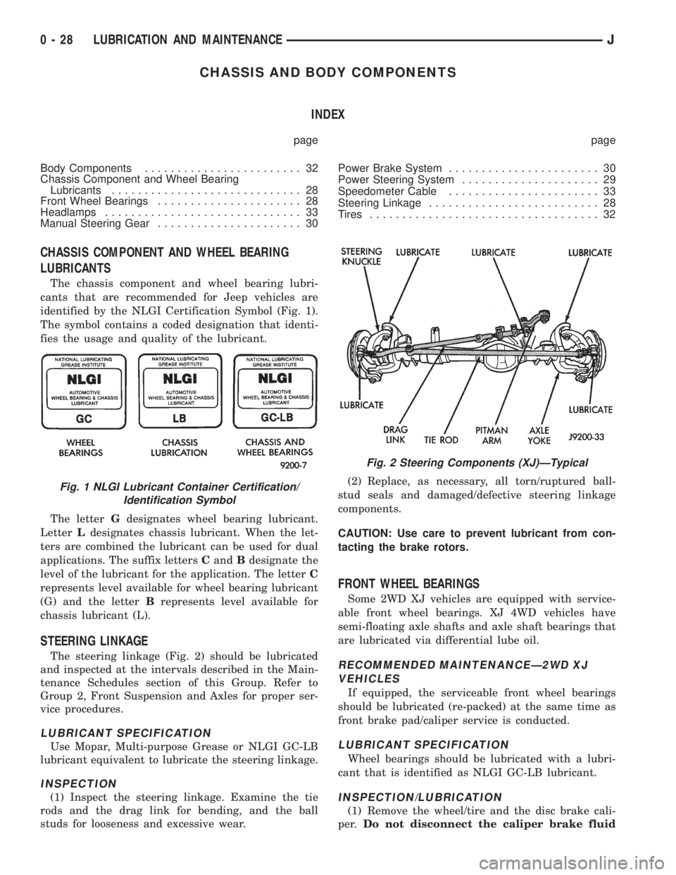
The chassis component and wheel bearing lubri-
cants that are recommended for Jeep vehicles are
identified by the NLGI Certification Symbol (Fig. 1).
The symbol contains a coded designation that identi-
fies the usage and quality of the lubricant.
The letterGdesignates wheel bearing lubricant.
LetterLdesignates chassis lubricant. When the let-
ters are combined the lubricant can be used for dual
applications. The suffix lettersCandBdesignate the
level of the lubricant for the application. The letterC
represents level available for wheel bearing lubricant
(G) and the letterBrepresents level available for
chassis lubricant (L).
STEERING LINKAGE
The steering linkage (Fig. 2) should be lubricated
and inspected at the intervals described in the Main-
tenance Schedules section of this Group. Refer to
Group 2, Front Suspension and Axles for proper ser-
vice procedures.
LUBRICANT SPECIFICATION
Use Mopar, Multi-purpose Grease or NLGI GC-LB
lubricant equivalent to lubricate the steering linkage.
INSPECTION
(1) Inspect the steering linkage. Examine the tie
rods and the drag link for bending, and the ball
studs for looseness and excessive wear.(2) Replace, as necessary, all torn/ruptured ball-
stud seals and damaged/defective steering linkage
components.
CAUTION: Use care to prevent lubricant from con-
tacting the brake rotors.
FRONT WHEEL BEARINGS
Some 2WD XJ vehicles are equipped with service-
able front wheel bearings. XJ 4WD vehicles have
semi-floating axle shafts and axle shaft bearings that
are lubricated via differential lube oil.
RECOMMENDED MAINTENANCEÐ2WD XJ
VEHICLES
If equipped, the serviceable front wheel bearings
should be lubricated (re-packed) at the same time as
front brake pad/caliper service is conducted.
LUBRICANT SPECIFICATION
Wheel bearings should be lubricated with a lubri-
cant that is identified as NLGI GC-LB lubricant.
INSPECTION/LUBRICATION
(1) Remove the wheel/tire and the disc brake cali-
per.Do not disconnect the caliper brake fluid
Fig. 1 NLGI Lubricant Container Certification/
Identification Symbol
Fig. 2 Steering Components (XJ)ÐTypical
0 - 28 LUBRICATION AND MAINTENANCEJ
Page 30 of 2198
hose unless the caliper must also be removed
for maintenance.Support the caliper with a
hanger to prevent brake fluid hose damage.
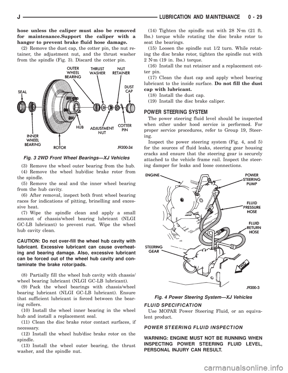
(2) Remove the dust cap, the cotter pin, the nut re-
tainer, the adjustment nut, and the thrust washer
from the spindle (Fig. 3). Discard the cotter pin.
(3) Remove the wheel outer bearing from the hub.
(4) Remove the wheel hub/disc brake rotor from
the spindle.
(5) Remove the seal and the inner wheel bearing
from the hub cavity.
(6) After removal, inspect both front wheel bearing
races for indications of pitting, brinelling and exces-
sive heat.
(7) Wipe the spindle clean and apply a small
amount of chassis/wheel bearing lubricant (NLGI
GC-LB lubricant) to prevent rust. Wipe the wheel
hub cavity clean.
CAUTION: Do not over-fill the wheel hub cavity with
lubricant. Excessive lubricant can cause overheat-
ing and bearing damage. Also, excessive lubricant
can be forced out of the wheel hub cavity and con-
taminate the brake rotor/pads.
(8) Partially fill the wheel hub cavity with chassis/
wheel bearing lubricant (NLGI GC-LB lubricant).
(9) Pack the wheel bearings with chassis/wheel
bearing lubricant (NLGI GC-LB lubricant). Ensure
that sufficient lubricant is forced between the bear-
ing rollers.
(10) Install the wheel inner bearing in the wheel
hub and install a replacement seal.
(11) Clean the disc brake rotor contact surfaces, if
necessary.
(12) Install the wheel hub/disc brake rotor on the
spindle.
(13) Install the wheel outer bearing, the thrust
washer, and the spindle nut.(14) Tighten the spindle nut with 28 Nzm (21 ft.
lbs.) torque while rotating the disc brake rotor to
seat the bearings.
(15) Loosen the spindle nut 1/2 turn. While rotat-
ing the disc brake rotor, tighten the spindle nut with
2Nzm (19 in. lbs.) torque.
(16) Install the nut retainer and a replacement cot-
ter pin.
(17) Clean the dust cap and apply wheel bearing
lubricant to the inside surface.Do not fill the dust
cap with lubricant.
(18) Install the dust cap.
(19) Install the disc brake caliper.
POWER STEERING SYSTEM
The power steering fluid level should be inspected
when other under hood service is performed. For
proper service procedures, refer to Group 19, Steer-
ing.
Inspect the power steering system (Fig. 4, and 5)
for the sources of fluid leaks, steering gear housing
cracks and ensure that the steering gear is securely
attached to the vehicle frame rail. Inspect the steer-
ing damper for leaks and loose connections.
FLUID SPECIFICATION
Use MOPAR Power Steering Fluid, or an equiva-
lent product.
POWER STEERING FLUID INSPECTION
WARNING: ENGINE MUST NOT BE RUNNING WHEN
INSPECTING POWER STEERING FLUID LEVEL,
PERSONAL INJURY CAN RESULT.
Fig. 3 2WD Front Wheel BearingsÐXJ Vehicles
Fig. 4 Power Steering SystemÐXJ Vehicles
JLUBRICATION AND MAINTENANCE 0 - 29
Page 37 of 2198
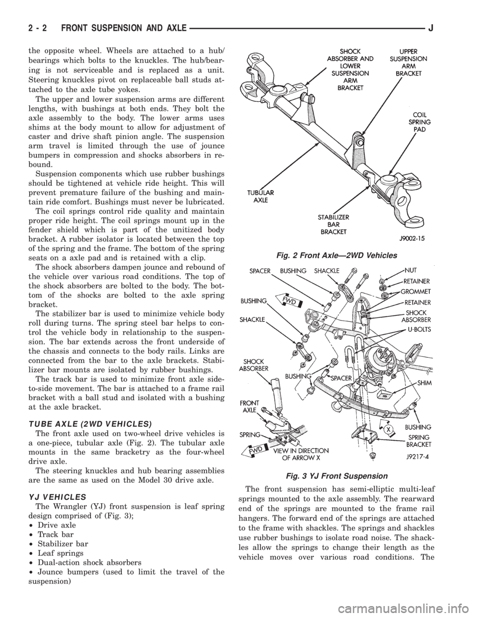
the opposite wheel. Wheels are attached to a hub/
bearings which bolts to the knuckles. The hub/bear-
ing is not serviceable and is replaced as a unit.
Steering knuckles pivot on replaceable ball studs at-
tached to the axle tube yokes.
The upper and lower suspension arms are different
lengths, with bushings at both ends. They bolt the
axle assembly to the body. The lower arms uses
shims at the body mount to allow for adjustment of
caster and drive shaft pinion angle. The suspension
arm travel is limited through the use of jounce
bumpers in compression and shocks absorbers in re-
bound.
Suspension components which use rubber bushings
should be tightened at vehicle ride height. This will
prevent premature failure of the bushing and main-
tain ride comfort. Bushings must never be lubricated.
The coil springs control ride quality and maintain
proper ride height. The coil springs mount up in the
fender shield which is part of the unitized body
bracket. A rubber isolator is located between the top
of the spring and the frame. The bottom of the spring
seats on a axle pad and is retained with a clip.
The shock absorbers dampen jounce and rebound of
the vehicle over various road conditions. The top of
the shock absorbers are bolted to the body. The bot-
tom of the shocks are bolted to the axle spring
bracket.
The stabilizer bar is used to minimize vehicle body
roll during turns. The spring steel bar helps to con-
trol the vehicle body in relationship to the suspen-
sion. The bar extends across the front underside of
the chassis and connects to the body rails. Links are
connected from the bar to the axle brackets. Stabi-
lizer bar mounts are isolated by rubber bushings.
The track bar is used to minimize front axle side-
to-side movement. The bar is attached to a frame rail
bracket with a ball stud and isolated with a bushing
at the axle bracket.
TUBE AXLE (2WD VEHICLES)
The front axle used on two-wheel drive vehicles is
a one-piece, tubular axle (Fig. 2). The tubular axle
mounts in the same bracketry as the four-wheel
drive axle.
The steering knuckles and hub bearing assemblies
are the same as used on the Model 30 drive axle.
YJ VEHICLES
The Wrangler (YJ) front suspension is leaf spring
design comprised of (Fig. 3);
²Drive axle
²Track bar
²Stabilizer bar
²Leaf springs
²Dual-action shock absorbers
²Jounce bumpers (used to limit the travel of the
suspension)The front suspension has semi-elliptic multi-leaf
springs mounted to the axle assembly. The rearward
end of the springs are mounted to the frame rail
hangers. The forward end of the springs are attached
to the frame with shackles. The springs and shackles
use rubber bushings to isolate road noise. The shack-
les allow the springs to change their length as the
vehicle moves over various road conditions. The
Fig. 2 Front AxleÐ2WD Vehicles
Fig. 3 YJ Front Suspension
2 - 2 FRONT SUSPENSION AND AXLEJ
Page 40 of 2198
FRONT WHEEL ALIGNMENT
INDEX
page page
Alignment Measurements and Adjustments....... 8
General Information........................ 5Pre-Alignment Inspection.................... 6
GENERAL INFORMATION
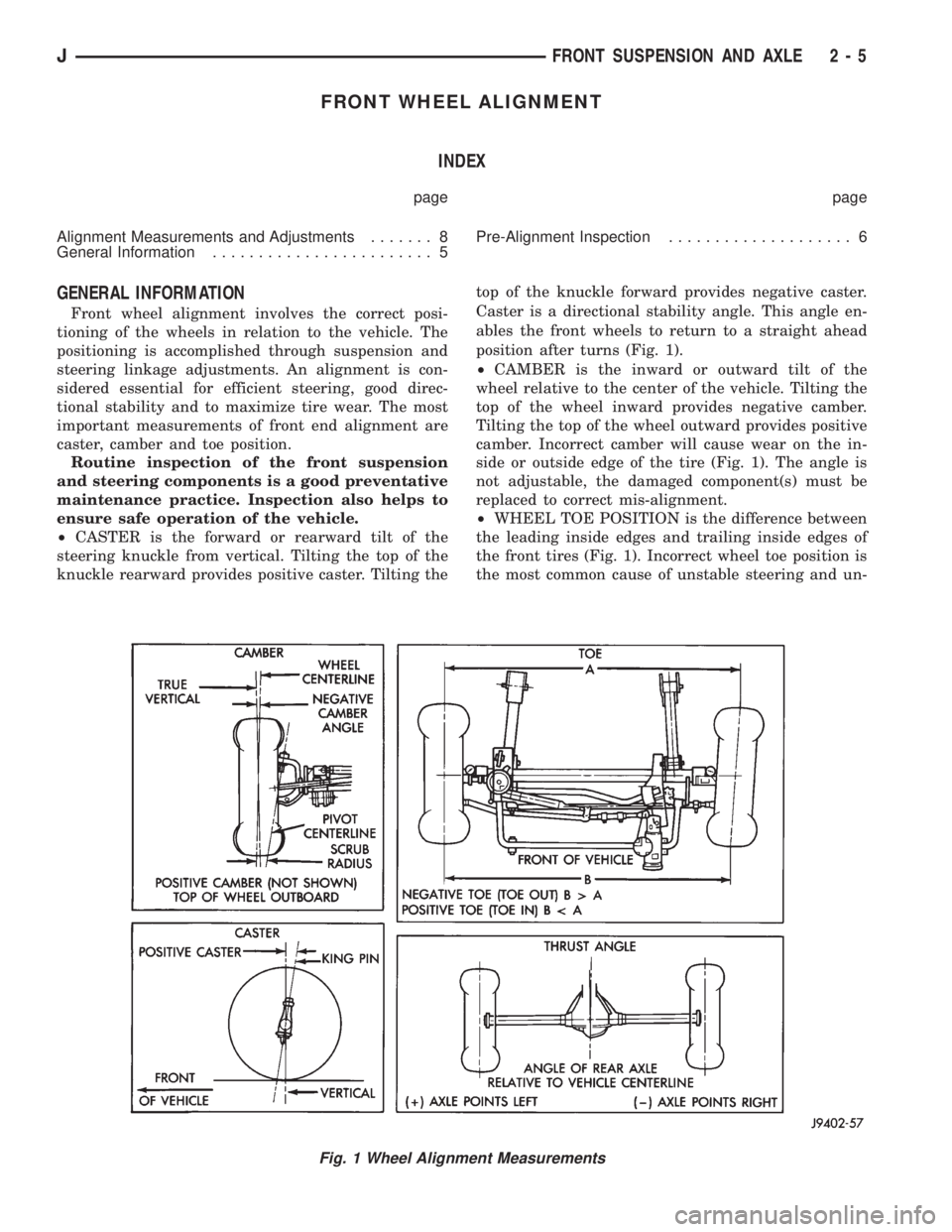
Front wheel alignment involves the correct posi-
tioning of the wheels in relation to the vehicle. The
positioning is accomplished through suspension and
steering linkage adjustments. An alignment is con-
sidered essential for efficient steering, good direc-
tional stability and to maximize tire wear. The most
important measurements of front end alignment are
caster, camber and toe position.
Routine inspection of the front suspension
and steering components is a good preventative
maintenance practice. Inspection also helps to
ensure safe operation of the vehicle.
²CASTER is the forward or rearward tilt of the
steering knuckle from vertical. Tilting the top of the
knuckle rearward provides positive caster. Tilting thetop of the knuckle forward provides negative caster.
Caster is a directional stability angle. This angle en-
ables the front wheels to return to a straight ahead
position after turns (Fig. 1).
²CAMBER is the inward or outward tilt of the
wheel relative to the center of the vehicle. Tilting the
top of the wheel inward provides negative camber.
Tilting the top of the wheel outward provides positive
camber. Incorrect camber will cause wear on the in-
side or outside edge of the tire (Fig. 1). The angle is
not adjustable, the damaged component(s) must be
replaced to correct mis-alignment.
²WHEEL TOE POSITION is the difference between
the leading inside edges and trailing inside edges of
the front tires (Fig. 1). Incorrect wheel toe position is
the most common cause of unstable steering and un-
Fig. 1 Wheel Alignment Measurements
JFRONT SUSPENSION AND AXLE 2 - 5