tow JEEP CHEROKEE 2014 KL / 5.G Owner's Guide
[x] Cancel search | Manufacturer: JEEP, Model Year: 2014, Model line: CHEROKEE, Model: JEEP CHEROKEE 2014 KL / 5.GPages: 690, PDF Size: 4.74 MB
Page 343 of 690
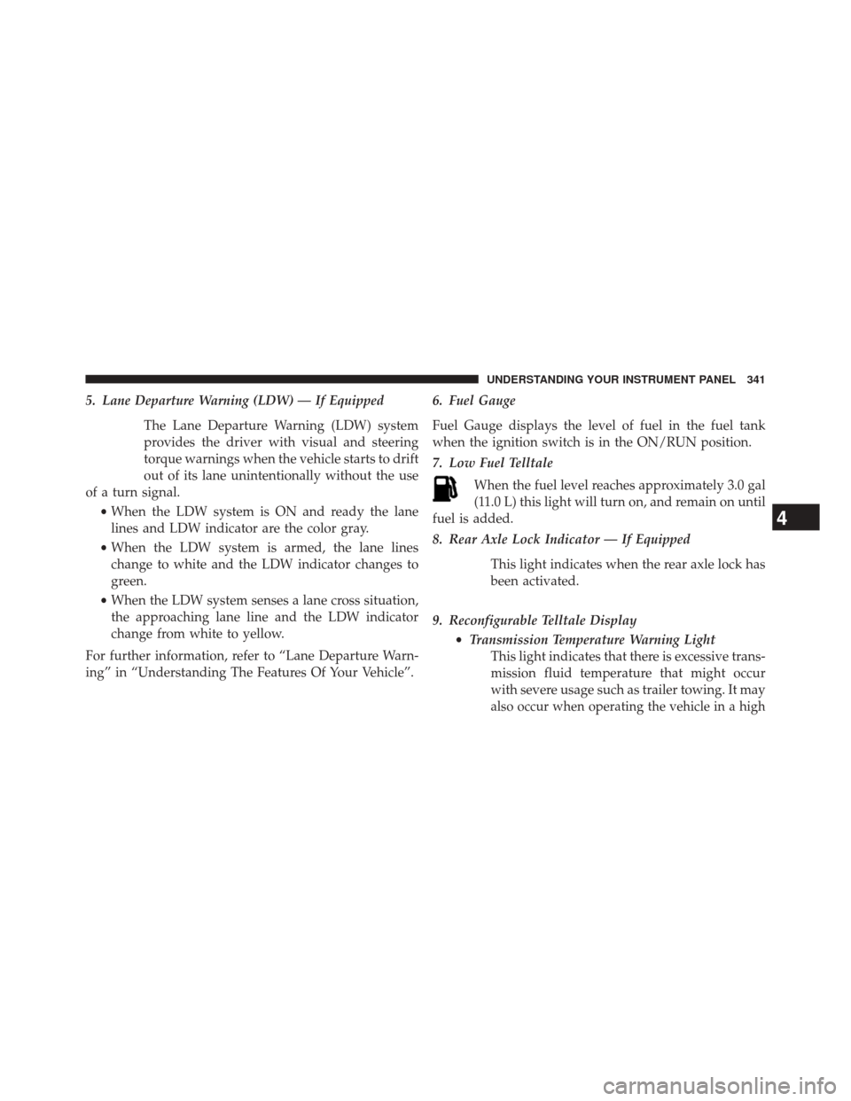
5. Lane Departure Warning (LDW) — If EquippedThe Lane Departure Warning (LDW) system
provides the driver with visual and steering
torque warnings when the vehicle starts to drift
out of its lane unintentionally without the use
of a turn signal.
•When the LDW system is ON and ready the lane
lines and LDW indicator are the color gray.
• When the LDW system is armed, the lane lines
change to white and the LDW indicator changes to
green.
• When the LDW system senses a lane cross situation,
the approaching lane line and the LDW indicator
change from white to yellow.
For further information, refer to “Lane Departure Warn-
ing” in “Understanding The Features Of Your Vehicle”. 6. Fuel Gauge
Fuel Gauge displays the level of fuel in the fuel tank
when the ignition switch is in the ON/RUN position.
7. Low Fuel Telltale
When the fuel level reaches approximately 3.0 gal
(11.0 L) this light will turn on, and remain on until
fuel is added.
8. Rear Axle Lock Indicator — If Equipped
This light indicates when the rear axle lock has
been activated.
9. Reconfigurable Telltale Display •Transmission Temperature Warning Light
This light indicates that there is excessive trans-
mission fluid temperature that might occur
with severe usage such as trailer towing. It may
also occur when operating the vehicle in a high
4
UNDERSTANDING YOUR INSTRUMENT PANEL 341
Page 348 of 690
If a problem is detected, the light will come on while
the engine is running. Cycle the ignition key when
the vehicle has completely stopped and the shift lever
is placed in the PARK position. The light should turn
off.
If the light remains lit with the engine running, your
vehicle will usually be drivable. However, see an
authorized dealer for service as soon as possible.
If the light is flashing when the engine is running,
immediate service is required. You may experience
reduced performance, an elevated/rough idle or en-
gine stall and your vehicle may require towing.
•Oil Temperature Warning Light
This telltale indicates engine oil temperature is
high. If the light turns on while driving, stop
the vehicle and shut off the engine as soon as
possible. •
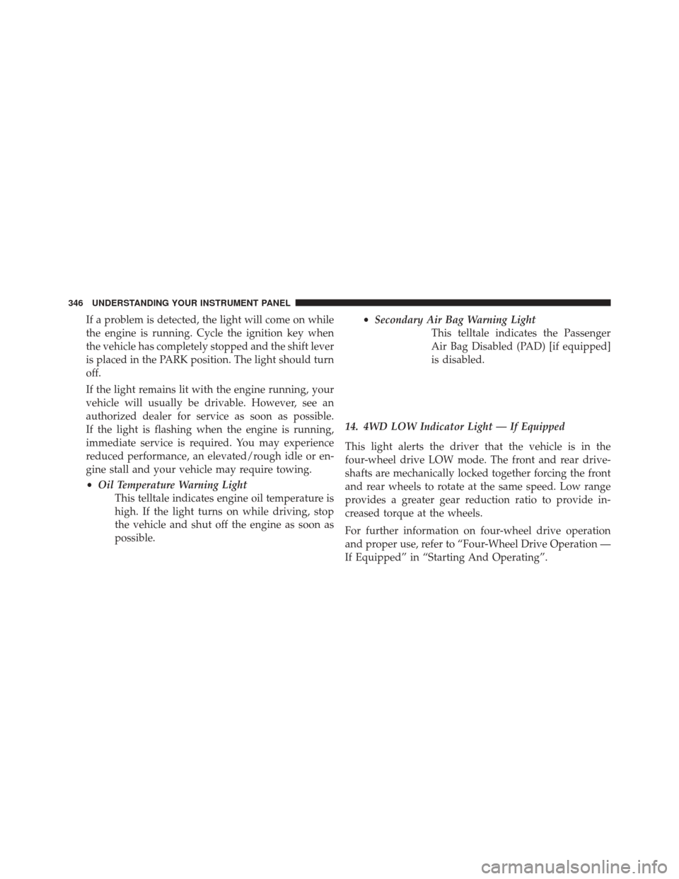
Secondary Air Bag Warning Light
This telltale indicates the Passenger
Air Bag Disabled (PAD) [if equipped]
is disabled.
14. 4WD LOW Indicator Light — If Equipped
This light alerts the driver that the vehicle is in the
four-wheel drive LOW mode. The front and rear drive-
shafts are mechanically locked together forcing the front
and rear wheels to rotate at the same speed. Low range
provides a greater gear reduction ratio to provide in-
creased torque at the wheels.
For further information on four-wheel drive operation
and proper use, refer to “Four-Wheel Drive Operation —
If Equipped” in “Starting And Operating”.
346 UNDERSTANDING YOUR INSTRUMENT PANEL
Page 349 of 690
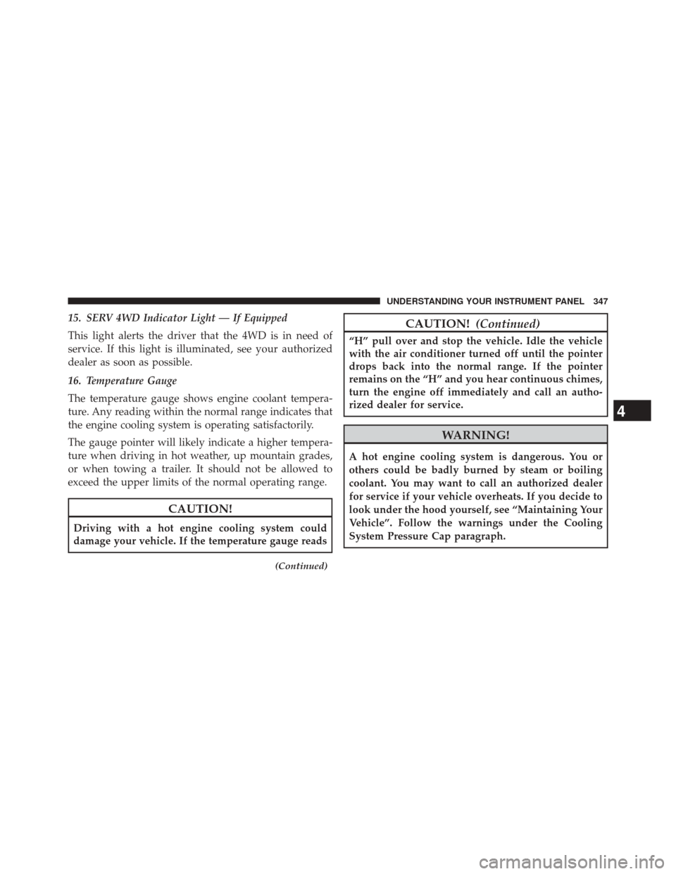
15. SERV 4WD Indicator Light — If Equipped
This light alerts the driver that the 4WD is in need of
service. If this light is illuminated, see your authorized
dealer as soon as possible.
16. Temperature Gauge
The temperature gauge shows engine coolant tempera-
ture. Any reading within the normal range indicates that
the engine cooling system is operating satisfactorily.
The gauge pointer will likely indicate a higher tempera-
ture when driving in hot weather, up mountain grades,
or when towing a trailer. It should not be allowed to
exceed the upper limits of the normal operating range.
CAUTION!
Driving with a hot engine cooling system could
damage your vehicle. If the temperature gauge reads
(Continued)
CAUTION!(Continued)
“H” pull over and stop the vehicle. Idle the vehicle
with the air conditioner turned off until the pointer
drops back into the normal range. If the pointer
remains on the “H” and you hear continuous chimes,
turn the engine off immediately and call an autho-
rized dealer for service.
WARNING!
A hot engine cooling system is dangerous. You or
others could be badly burned by steam or boiling
coolant. You may want to call an authorized dealer
for service if your vehicle overheats. If you decide to
look under the hood yourself, see “Maintaining Your
Vehicle”. Follow the warnings under the Cooling
System Pressure Cap paragraph.
4
UNDERSTANDING YOUR INSTRUMENT PANEL 347
Page 355 of 690
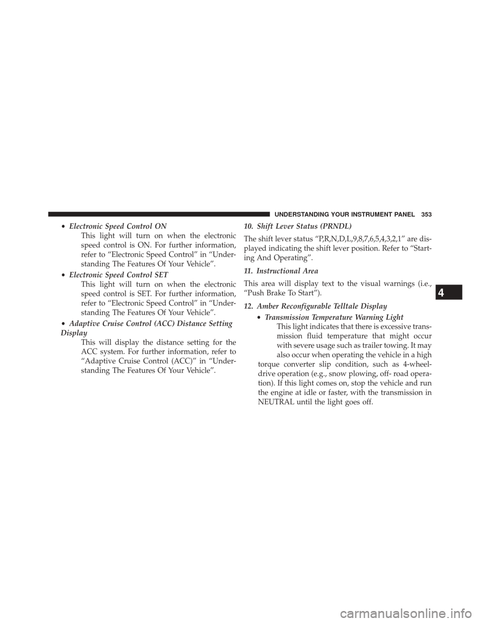
•Electronic Speed Control ON
This light will turn on when the electronic
speed control is ON. For further information,
refer to “Electronic Speed Control” in “Under-
standing The Features Of Your Vehicle”.
• Electronic Speed Control SET
This light will turn on when the electronic
speed control is SET. For further information,
refer to “Electronic Speed Control” in “Under-
standing The Features Of Your Vehicle”.
• Adaptive Cruise Control (ACC) Distance Setting
Display This will display the distance setting for the
ACC system. For further information, refer to
“Adaptive Cruise Control (ACC)” in “Under-
standing The Features Of Your Vehicle”. 10. Shift Lever Status (PRNDL)
The shift lever status “P,R,N,D,L,9,8,7,6,5,4,3,2,1” are dis-
played indicating the shift lever position. Refer to “Start-
ing And Operating”.
11. Instructional Area
This area will display text to the visual warnings (i.e.,
“Push Brake To Start”).
12. Amber Reconfigurable Telltale Display
•Transmission Temperature Warning Light
This light indicates that there is excessive trans-
mission fluid temperature that might occur
with severe usage such as trailer towing. It may
also occur when operating the vehicle in a high
torque converter slip condition, such as 4-wheel-
drive operation (e.g., snow plowing, off- road opera-
tion). If this light comes on, stop the vehicle and run
the engine at idle or faster, with the transmission in
NEUTRAL until the light goes off.
4
UNDERSTANDING YOUR INSTRUMENT PANEL 353
Page 358 of 690
If your odometer needs to be repaired or serviced, the
repair technician should leave the odometer reading
the same as it was before the repair or service. If s/he
cannot do so, then the odometer must be set at zero,
and a sticker must be placed in the door jamb stating
what the mileage was before the repair or service. It
is a good idea for you to make a record of the
odometer reading before the repair/service, so that
you can be sure that it is properly reset, or that the
door jamb sticker is accurate if the odometer must be
reset at zero.
When the appropriate conditions exist, this display
shows the Electronic Vehicle Information Center
(EVIC) messages and Submenus.
•Fuel Gauge
Fuel Gauge displays the level of fuel in the fuel tank
when the ignition switch is in the ON/RUN position. •
Temperature Gauge
The temperature gauge shows engine coolant tem-
perature. Any reading within the normal range indi-
cates that the engine cooling system is operating
satisfactorily.
The gauge pointer will likely indicate a higher tem-
perature when driving in hot weather, up mountain
grades, or when towing a trailer. It should not be
allowed to exceed the upper limits of the normal
operating range.
CAUTION!
Driving with a hot engine cooling system could
damage your vehicle. If the temperature gauge reads
“H” pull over and stop the vehicle. Idle the vehicle
with the air conditioner turned off until the pointer
drops back into the normal range. If the pointer
(Continued)
356 UNDERSTANDING YOUR INSTRUMENT PANEL
Page 362 of 690
If the light remains lit with the engine running, your
vehicle will usually be drivable. However, see an
authorized dealer for service as soon as possible. If
the light is flashing when the engine is running,
immediate service is required. You may experience
reduced performance, an elevated/rough idle or en-
gine stall and your vehicle may require towing.
•Oil Temperature Warning Light
This telltale indicates engine oil tempera-
ture is high. If the light turns on while
driving, stop the vehicle and shut off the
engine as soon as possible.
• Air Bag Warning Light
This light will turn on for four to eight
seconds as a bulb check when the ignition
switch is first turned to the ON/RUN po-
sition. If the light is either not on during
starting, stays on, or turns on while driving, have the
system inspected at an authorized dealer as soon as possible. Refer to “Occupant Restraints” in “Things
To Know Before Starting Your Vehicle” for further
information.
Engine Oil Change Indicator System
Oil Change Required
Your vehicle is equipped with an engine oil change
indicator system. The “Oil Change Required” message
will display in the EVIC for five seconds after a single
chime has sounded, to indicate the next scheduled oil
change interval. The engine oil change indicator system
is duty cycle based, which means the engine oil change
interval may fluctuate, dependent upon your personal
driving style.
Unless reset, this message will continue to display each
time you turn the ignition switch to the ON/RUN
position or cycle the ignition to the ON/RUN position if
equipped with Keyless Enter-N-Go™. To turn off the
message temporarily, press and release the OK button.
360 UNDERSTANDING YOUR INSTRUMENT PANEL
Page 399 of 690
NOTE:
•If the RECIRCULATION button is pressed when the
system is in Defrost mode the Recirculation LED
indicator will flash three times and then turn off to
indicate Recirculation mode is not allowed.
• Continuous use of the Recirculation mode may make
the inside air stuffy and window fogging may occur.
Extended use of this mode is not recommended.
• In cold or damp weather, the use of the Recirculation
mode will cause windows to fog on the inside because
of moisture buildup inside the vehicle. For maximum
defogging, select the outside air position.
• The A/C can be deselected manually without disturb-
ing the mode control selection by pressing the A/C
button.Air Outlets
The airflow from each of the instrument panel outlets can
be adjusted for direction, and turned on or off to control
airflow.
NOTE: For maximum airflow to the rear, the center
instrument panel outlets can be directed toward the rear
seat passengers.
Economy Mode
If ECONOMY mode is desired, press the A/C button to
turn off the LED indicator and the A/C compressor.
Rotate the temperature control knob to the desired tem-
perature. Also, make sure to select only Panel, Bi-Level or
Floor modes.
Stop/Start System — If Equipped
While in an Autostop, the Climate Controls system may
automatically adjust airflow to maintain cabin comfort.
Customer settings will be maintained upon return to an
engine running condition.
4
UNDERSTANDING YOUR INSTRUMENT PANEL 397
Page 404 of 690
NOTE:BI-LEVEL mode is designed under comfort con-
ditions to provide cooler air out of the panel outlets and
warmer air from the floor outlets.
•Floor Mode
Air comes from the floor outlets. A slight amount
of air is directed through the defrost and side
window demister outlets.
• Mix Mode
Air comes from the floor, defrost and side window
demist outlets. This mode works best in cold or
snowy conditions.
NOTE: The air conditioning compressor operates in MIX
and DEFROST modes even if the A/C button is not
pressed. This dehumidifies the air to help dry the wind-
shield. To improve fuel economy, use these modes only
when necessary.
8. Climate Control OFF Button
Press and release this button to turn the Climate Control
ON/OFF. 9. Temperature Control Down Button (Uconnect® 8.4)
Provides temperature control. Push the hard-key button
for cooler temperature settings or on the touchscreen,
touch and slide the soft-key temperature bar towards the
blue arrow soft-key for cooler temperature settings.
10. Temperature Control Up Button (Uconnect® 8.4)
Provides temperature control. Push the hard-key button
for warmer temperature settings or on the touchscreen,
touch and slide the soft-key temperature bar towards the
red arrow soft-key for warmer temperature settings.
11. Temperature Control (Uconnect® 5.0)
Touch the temperature soft-key to regulate the tempera-
ture of the air inside the passenger compartment. Moving
the temperature bar into the red area, indicates warmer
temperatures. Moving the temperature bar into the blue
area indicates cooler temperatures.
402 UNDERSTANDING YOUR INSTRUMENT PANEL
Page 407 of 690
6. Rear Defrost Button
Press and release this button to turn on the rear window
defroster and the heated outside mirrors (if equipped).
An indicator will illuminate when the rear window
defroster is on. The rear window defroster automatically
turns off after 10 minutes. For each additional press of
this button, five additional minutes will be added to the
timer function.
CAUTION!
Failure to follow these cautions can cause damage to
the heating elements:
•Use care when washing the inside of the rear
window. Do not use abrasive window cleaners on
the interior surface of the window. Use a soft cloth
and a mild washing solution, wiping parallel to the
heating elements. Labels can be peeled off after
soaking with warm water.
(Continued)
CAUTION!
(Continued)
•Do not use scrapers, sharp instruments, or abrasive
window cleaners on the interior surface of the
window.
• Keep all objects a safe distance from the window.
7. Passenger Temperature Control Up Button
Provides the passenger with independent temperature
control. Push the hard-key button for warmer tempera-
ture settings or on the touchscreen, touch and slide the
soft-key temperature bar towards the red arrow soft-key
for warmer temperature settings.
NOTE: Pressing this button while in Sync mode will
automatically exit Sync.
4
UNDERSTANDING YOUR INSTRUMENT PANEL 405
Page 408 of 690
8. Passenger Temperature Control Down Button
Provides the passenger with independent temperature
control. Push the hard-key button for cooler temperature
settings or on the touchscreen, touch and slide the
soft-key temperature bar towards the blue arrow soft-key
for cooler temperature settings.
NOTE:Pressing this button while in Sync mode will
automatically exit Sync.
9. SYNC
Touch the Sync soft-key to toggle the Sync feature
On/Off. The Sync indicator is illuminated when this
feature is enabled. Sync is used to synchronize the
passenger temperature setting with the driver tempera-
ture setting. Changing the passenger temperature setting
while in Sync will automatically exit this feature. 10. Blower Control
Blower control is used to regulate the amount of air
forced through the climate system. There are seven
blower speeds available. Adjusting the blower will cause
automatic mode to switch to manual operation. The
speeds can be selected using either hard-keys or soft-keys
as follows:
Hard-Key
The blower speed increases as you turn the control
clockwise from the lowest blower setting. The blower
speed decreases as you turn the knob counterclockwise.
Soft-Key
Use the small blower icon to reduce the blower setting
and the large blower icon to increase the blower setting.
Blower can also be selected by pressing the blower bar
area between the icons.
406 UNDERSTANDING YOUR INSTRUMENT PANEL