door lock JEEP CHEROKEE 2014 KL / 5.G Owner's Manual
[x] Cancel search | Manufacturer: JEEP, Model Year: 2014, Model line: CHEROKEE, Model: JEEP CHEROKEE 2014 KL / 5.GPages: 204, PDF Size: 3.84 MB
Page 124 of 204
PROGRAMMABLE FEATURES
Uconnect® Customer Programmable Features
The Uconnect®system allows you to access Customer Programmable feature
settings such as Display, Clock, Safety/Assistance, Lights, Doors & Locks, Auto-On
Comfort & Remote Start, Engine Off Operation, Audio, Phone/Bluetooth
®and
SiriusXM Setup and System Information through soft-keys.
• Touch the “Apps” soft-key located near the bottom of the screen, then touch the “Settings” soft-key to access the Settings screen. When making a selection, scroll
up or down until the preferred setting is highlighted, then press and release the
preferred setting until a check-mark appears next to the setting, showing that
setting has been selected. The following feature settings are available:
• Display • Clock
• Safety/Assistance • Doors & Locks
• Auto-On Comfort & Remote Start • Engine Off Options
• Phone/Bluetooth
®• Audio
• Lights • SiriusXM Setup
• Units • System Information
• Voice
NOTE:
Depending on the vehicles options, feature settings may vary.
UNIVERSAL GARAGE DOOR OPENER (HomeLink®)
• HomeLink®replaces up to three hand-
held transmitters that operate devices
such as garage door openers, motor-
ized gates, lighting or home security
systems. The HomeLink
®unit is pow-
ered by your vehicles 12 Volt battery.
• The HomeLink
®buttons that are lo-
cated in the overhead console or sun-
visor designate the three different
HomeLink
®channels.
• The HomeLink
®indicator is located
above the center button.
ELECTRONICS
122
Page 127 of 204
Using HomeLink®
To operate, press and release the programmed HomeLink®button. Activation will
now occur for the programmed device (i.e., garage door opener, gate operator,
security system, entry door lock, home/office lighting, etc.,). The hand-held trans-
mitter of the device may also be used at any time.
WARNING!
• Your motorized door or gate will open and close while you are programming the universal transceiver. Do not program the transceiver if people or pets are in the
path of the door or gate.
• Do not run your vehicle in a closed garage or confined area while programming
the transceiver. Exhaust gas from your vehicle contains Carbon Monoxide (CO)
which is odorless and colorless. Carbon Monoxide is poisonous when inhaled
and can cause you and others to be severely injured or killed.
POWER INVERTER
• There is a 115 Volt, 150 Watt powerinverter outlet located on the back of
the center console. This outlet can
power cellular phones, electronics and
other low power devices requiring
power up to 150 Watts.
NOTE:
The power inverter is designed with
built-in overload protection. If the power
rating of 150 Watts is exceeded, the power
inverter will automatically shut down.
Once the electrical device has been re-
moved from the outlet, the inverter should
automatically reset. If the power rating
exceeds approximately 170 Watts, the
power inverter may have to be reset manually. To reset the inverter manually, unplug the
device and plug it in again. To avoid overloading the circuit, check the power ratings on
electrical devices prior to using the inverter.
WARNING!
To Avoid Serious Injury or Death DO NOT:
• insert any objects into the receptacles
• touch with wet hands
Close the lid when not in use. If this outlet is mishandled, it may cause an electric
shock and failure.
ELECTRONICS
125
Page 158 of 204
If the tire pressure is 19 psi (1.3 Bar) or higher:
1. Press the Power Button (4) to turn on TIREFIT and inflate the tire to the pressureindicated on the tire and loading information label on the driver-side door
opening.
2. Disconnect the TIREFIT kit from the valve stem, reinstall the cap on the valve stem and unplug from 12 Volt outlet.
3. Place the TIREFIT kit in its proper storage area in the vehicle.
4. Have the tire inspected and repaired or replaced at the earliest opportunity at an authorized dealer or tire service center.
5. Replace the Sealant Bottle (1) and Sealant Hose (6) assembly at your authorized dealer as soon as possible. Refer to “(F) Sealant Bottle and Hose Replacement.”
NOTE:
• If the tire becomes over-inflated, press the Deflation Button to reduce the tire pressure to the recommended inflation pressure before continuing.
• When having the tire serviced, advise the authorized dealer or service center that the tire has been sealed using the TIREFIT service kit.
(F) Sealant Bottle And Hose Replacement:
1. Uncoil the Sealant Hose (6) (clear in color).
2. Locate the round Sealant Bottle release button in the recessed area under the
sealant bottle.
3. Press the Sealant Bottle release button. The Sealant Bottle (1) will pop up. Remove the bottle and dispose of it accordingly.
4. Clean any remaining sealant from the TIREFIT housing.
5. Position the new Sealant Bottle (1) in the housing so that the Sealant Hose (6) aligns with the hose slot in the front of the housing. Press the bottle into the
housing. An audible click will be heard indicating the bottle is locked into place.
6. Verify that the cap is installed on the fitting at the end of the Sealant Hose (6) and return the hose to its storage area (located on the bottom of the air pump).
7. Return the TIREFIT kit to its storage location in the vehicle.
WHAT TO DO IN EMERGENCIES
156
Page 183 of 204
Cavity Blade Fuse Cartridge FuseDescription
F56 15 Amp Blue — Ignition Node Module (IGNM)/
KIN/RF Hub/Electric SteeringColumn Lock (ESL)
F57 20 Amp Yellow —Fuel Pump Motor
F58 10 Amp Red —Occupant Classification
Module
F59 — — Not Used
F60 20 Amp Yellow —Power Outlet — Center
Console
F61 — — Not Used
F62 10 Amp Red — Heated Mirrors — If Equipped
F63 25 Amp Clear —Front Heated Seats — If
Equipped
F64 25 Amp Clear —Heated Steering Wheel / Rear
Heated Seats — If Equipped
F65 15 Amp Blue —HVAC (ECC) / Instrument
Panel Cluster (IPC)
F66 10 Amp Red —In Car Temperature Sensor /
Humidity Sensor / Driver Assist System Module (DASM) / Park Assist (PAM)
F67 — — Not Used
F68 — — Not Used
F69 10 Amp Red —Power Transfer Unit Switch
(TSBM) / Active Grill Shutter (AGS) — If Equipped
F70 — — Not Used
F71 20 Amp Yellow —Windshield De-Icer — If
Equipped
F72 5 Amp Tan —Intelligent Battery Sensor
(IBS) — If Equipped With Stop/Start Engine Option
F72 20 Amp Yellow —Trailer Tow RT Stop / Turn
Lights — If Equipped
F73 —30 Amp Pink Rear Defroster / Defogger
F74 —20 Amp Blue Engine Control Module (ECM)
Gasoline Engine — IfEquipped
F75 20 Amp Yellow —Cigar Lighter
F76 20 Amp Yellow —Rear Differential Module
(RDM) — If Equipped
F77 10 Amp Red — Fuel Door Release/Brake Pedal
Switch
MAINTAINING YOUR VEHICLE
181
Page 185 of 204
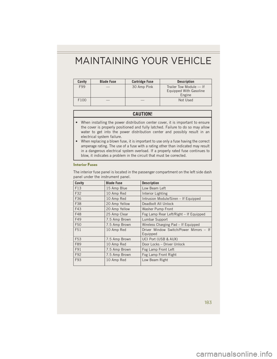
Cavity Blade Fuse Cartridge FuseDescription
F99 —30 Amp Pink Trailer Tow Module — If
Equipped With GasolineEngine
F100 — — Not Used
CAUTION!
• When installing the power distribution center cover, it is important to ensure
the cover is properly positioned and fully latched. Failure to do so may allow
water to get into the power distribution center and possibly result in an
electrical system failure.
•
When replacing a blown fuse, it is important to use only a fuse having the correct
amperage rating. The use of a fuse with a rating other than indicated may result
in a dangerous electrical system overload. If a properly rated fuse continues to
blow, it indicates a problem in the circuit that must be corrected.
Interior Fuses
The interior fuse panel is located in the passenger compartment on the left side dash
panel under the instrument panel.
Cavity Blade Fuse Description
F13 15 Amp Blue Low Beam Left
F32 10 Amp Red Interior Lighting
F36 10 Amp Red Intrusion Module/Siren – If Equipped
F38 20 Amp Yellow Deadbolt All Unlock
F43 20 Amp Yellow Washer Pump Front
F48 25 Amp Clear Fog Lamp Rear Left/Right – If Equipped
F49 7.5 Amp Brown Lumbar Support
F50 7.5 Amp Brown Wireless Charging Pad – If Equipped
F51 10 Amp Red Driver Window Switch/Power Mirrors – If
Equipped
F53 7.5 Amp Brown UCI Port (USB & AUX)
F89 10 Amp Red Door Locks – Driver Unlock
F91 7.5 Amp Brown Fog Lamp Front Left
F92 7.5 Amp Brown Fog Lamp Front Right
F93 10 Amp Red Low Beam Right
MAINTAINING YOUR VEHICLE
183
Page 190 of 204
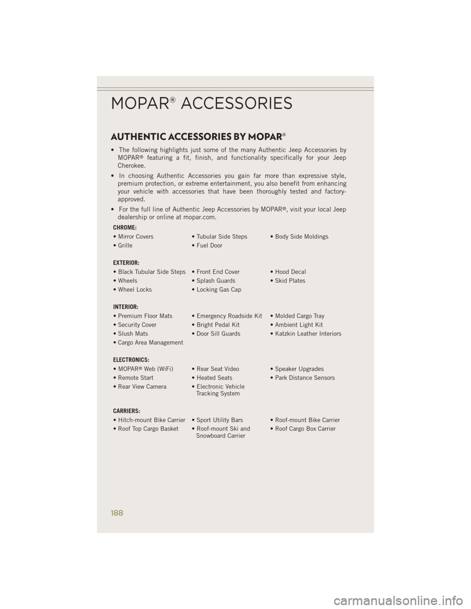
AUTHENTIC ACCESSORIES BY MOPAR®
• The following highlights just some of the many Authentic Jeep Accessories byMOPAR®featuring a fit, finish, and functionality specifically for your Jeep
Cherokee.
• In choosing Authentic Accessories you gain far more than expressive style, premium protection, or extreme entertainment, you also benefit from enhancing
your vehicle with accessories that have been thoroughly tested and factory-
approved.
• For the full line of Authentic Jeep Accessories by MOPAR
®, visit your local Jeep
dealership or online at mopar.com.
CHROME:
• Mirror Covers • Tubular Side Steps • Body Side Moldings
• Grille • Fuel Door
EXTERIOR:
• Black Tubular Side Steps • Front End Cover • Hood Decal
• Wheels • Splash Guards• Skid Plates
• Wheel Locks • Locking Gas Cap
INTERIOR:
• Premium Floor Mats • Emergency Roadside Kit • Molded Cargo Tray
• Security Cover • Bright Pedal Kit • Ambient Light Kit
• Slush Mats • Door Sill Guards • Katzkin Leather Interiors
• Cargo Area Management
ELECTRONICS:
• MOPAR
®Web (WiFi) • Rear Seat Video • Speaker Upgrades
• Remote Start • Heated Seats• Park Distance Sensors
• Rear View Camera • Electronic Vehicle Tracking System
CARRIERS:
• Hitch-mount Bike Carrier • Sport Utility Bars • Roof-mount Bike Carrier
• Roof Top Cargo Basket • Roof-mount Ski and Snowboard Carrier• Roof Cargo Box Carrier
MOPAR® ACCESSORIES
188
Page 191 of 204
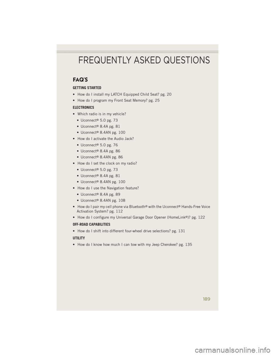
FAQ’S
GETTING STARTED
• How do I install my LATCH Equipped Child Seat? pg. 20
• How do I program my Front Seat Memory? pg. 25
ELECTRONICS
• Which radio is in my vehicle?• Uconnect
®5.0 pg. 73
• Uconnect
®8.4A pg. 81
• Uconnect
®8.4AN pg. 100
• How do I activate the Audio Jack?
• Uconnect
®5.0 pg. 76
• Uconnect
®8.4A pg. 86
• Uconnect
®8.4AN pg. 86
• How do I set the clock on my radio?
• Uconnect
®5.0 pg. 73
• Uconnect
®8.4A pg. 81
• Uconnect
®8.4AN pg. 100
• How do I use the Navigation feature?
• Uconnect
®8.4A pg. 89
• Uconnect
®8.4AN pg. 108
• How do I pair my cell phone via Bluetooth
®with the Uconnect®Hands-Free Voice
Activation System? pg. 112
• How do I configure my Universal Garage Door Opener (HomeLink
®)? pg. 122
OFF-ROAD CAPABILITIES
• How do I shift into different four-wheel drive selections? pg. 131
UTILITY
• How do I know how much I can tow with my Jeep Cherokee? pg. 135
FREQUENTLY ASKED QUESTIONS
189
Page 194 of 204
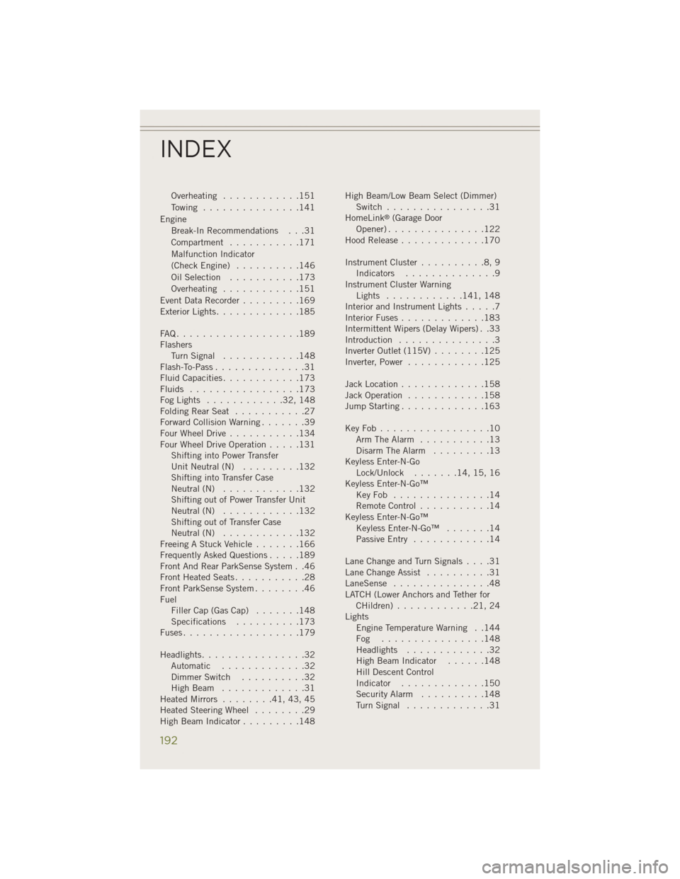
Overheating............151
Towing ...............141
Engine Break-In Recommendations . . .31
Compartment ...........171
Malfunction Indicator
(CheckEngine) ..........146
OilSelection ...........173
Overheating ............151
Event Data Recorder .........169
Exterior Lights .............185
FAQ...................189
Flashers TurnSignal ............148
Flash-To-Pass ..............31
Fluid Capacities ............173
Fluids .................173
FogLights ............32,148
FoldingRearSeat ...........27
Forward Collision Warning .......39
Four Wheel Drive ...........134
Four Wheel Drive Operation .....131
Shifting into Power Transfer
Unit Neutral (N) .........132
Shifting into Transfer Case
Neutral (N) ............132
Shifting out of Power Transfer Unit
Neutral (N) ............132
Shifting out of Transfer Case
Neutral (N) ............132
Freeing A Stuck Vehicle .......166
Frequently Asked Questions .....189
Front And Rear ParkSense System . .46
Front Heated Seats ...........28
Front ParkSense System ........46
Fuel Filler Cap (Gas Cap) .......148
Specifications ..........173
Fuses..................179
Headlights ................32
Automatic .............32
Dimmer Switch ..........32
HighBeam .............31
Heated Mirrors ........41,43,45
Heated Steering Wheel ........29
High Beam Indicator .........148 High Beam/Low Beam Select (Dimmer)
Switch ................31
HomeLink
®(Garage Door
Opener)...............122
Hood Release .............170
Instrument Cluster ..........8,9
Indicators ..............9
Instrument Cluster Warning Lights ............ 141, 148
Interior and Instrument Lights .....7
Interior Fuses .............183
Intermittent Wipers (Delay Wipers) . .33
Introduction ...............3
Inverter Outlet (115V) ........125
Inverter, Power ............125
Jack Location .............158
Jack Operation ............158
Jump Starting .............163
KeyFob.................10 Arm The Alarm ...........13
Disarm The Alarm .........13
Keyless Enter-N-Go Lock/Unlock .......14,15,16
Keyless Enter-N-Go™ KeyFob ...............14
Remote Control ...........14
Keyless Enter-N-Go™ Keyless Enter-N-Go™ .......14
Passive Entry ............14
LaneChangeandTurnSignals....31
Lane Change Assist ..........31
LaneSense ...............48
LATCH (Lower Anchors and Tether for CHildren)............21,24
Lights Engine Temperature Warning . .144
Fog ................148
Headlights .............32
High Beam Indicator ......148
Hill Descent Control
Indicator .............150
Security Alarm ..........148
TurnSignal .............31
INDEX
192