tow JEEP CHEROKEE 2014 KL / 5.G User Guide
[x] Cancel search | Manufacturer: JEEP, Model Year: 2014, Model line: CHEROKEE, Model: JEEP CHEROKEE 2014 KL / 5.GPages: 204, PDF Size: 3.84 MB
Page 3 of 204
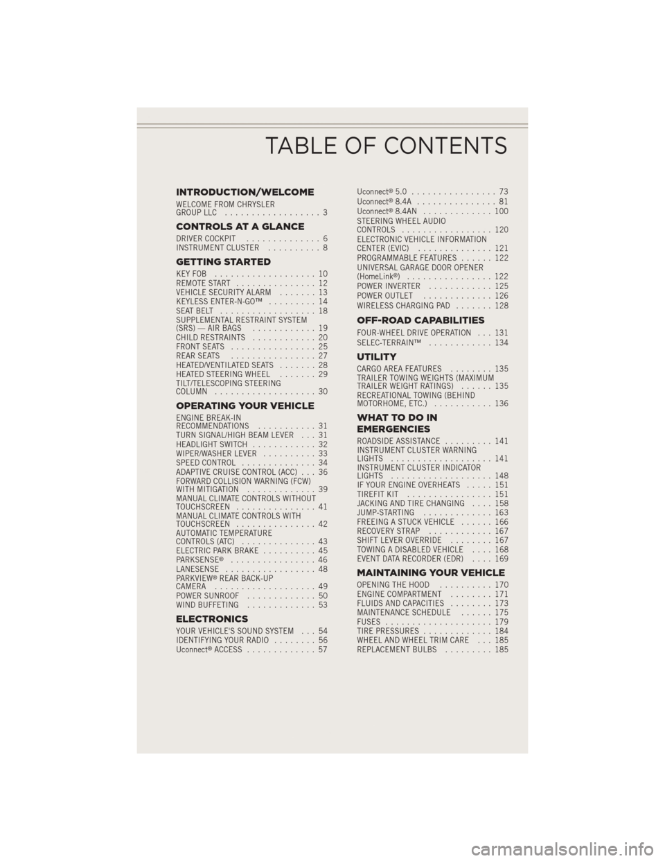
INTRODUCTION/WELCOME
WELCOME FROM CHRYSLER
GROUP LLC.................. 3
CONTROLS AT A GLANCE
DRIVER COCKPIT .............. 6
INSTRUMENT CLUSTER .......... 8
GETTING STARTED
KEYFOB ................... 10
REMOTE START............... 12
VEHICLE SECURITY ALARM ....... 13
KEYLESS ENTER-N-GO™ ......... 14
SEATBELT .................. 18
SUPPLEMENTAL RESTRAINT SYSTEM
(SRS) — AIR BAGS ............ 19
CHILD RESTRAINTS ............ 20
FRONT SEATS ................ 25
REAR SEATS ................ 27
HEATED/VENTILATED SEATS ....... 28
HEATED STEERING WHEEL ....... 29
TILT/TELESCOPING STEERING
COLUMN ................... 30
OPERATING YOUR VEHICLE
ENGINE BREAK-IN
RECOMMENDATIONS ........... 31
TURN SIGNAL/HIGH BEAM LEVER . . . 31
HEADLIGHT SWITCH ............ 32
WIPER/WASHER LEVER .......... 33
SPEED CONTROL .............. 34
ADAPTIVE CRUISE CONTROL (ACC) . . . 36
FORWARD COLLISION WARNING (FCW)
WITHMITIGATION ............. 39
MANUAL CLIMATE CONTROLS WITHOUT
TOUCHSCREEN ............... 41
MANUAL CLIMATE CONTROLS WITH
TOUCHSCREEN ............... 42
AUTOMATIC TEMPERATURE
CONTROLS (ATC) .............. 43
ELECTRIC PARK BRAKE .......... 45
PARKSENSE
®................ 46
LANESENSE ................. 48
PARKVIEW
®REAR BACK-UP
CAMERA ................... 49
POWER SUNROOF ............. 50
WIND BUFFETING ............. 53
ELECTRONICS
YOUR VEHICLE'S SOUND SYSTEM . . . 54
IDENTIFYING YOUR RADIO ........ 56
Uconnect
®ACCESS ............. 57 Uconnect
®5.0 ................ 73
Uconnect®8.4A ............... 81
Uconnect®8.4AN ............. 100
STEERING WHEEL AUDIO
CONTROLS ................. 120
ELECTRONIC VEHICLE INFORMATION
CENTER (EVIC) .............. 121
PROGRAMMABLE FEATURES ...... 122
UNIVERSAL GARAGE DOOR OPENER
(HomeLink
®) ................ 122
POWER INVERTER ............ 125
POWER OUTLET ............. 126
WIRELESS CHARGING PAD ....... 128
OFF-ROAD CAPABILITIES
FOUR-WHEEL DRIVE OPERATION . . . 131
SELEC-TERRAIN™............ 134
UTILITY
CARGO AREA FEATURES ........ 135
TRAILER TOWING WEIGHTS (MAXIMUM
TRAILER WEIGHT RATINGS) ...... 135
RECREATIONAL TOWING (BEHIND
MOTORHOME, ETC.) ........... 136
WHATTODOIN
EMERGENCIES
ROADSIDE ASSISTANCE ......... 141
INSTRUMENT CLUSTER WARNING
LIGHTS ................... 141
INSTRUMENT CLUSTER INDICATOR
LIGHTS ................... 148
IF YOUR ENGINE OVERHEATS ..... 151
TIREFIT KIT ................ 151
JACKING AND TIRE CHANGING .... 158
JUMP-STARTING ............. 163
FREEING A STUCK VEHICLE ...... 166
RECOVERY STRAP ............ 167
SHIFT LEVER OVERRIDE ........ 167
TOWING A DISABLED VEHICLE .... 168
EVENT DATA RECORDER (EDR) .... 169
MAINTAINING YOUR VEHICLE
OPENING THE HOOD.......... 170
ENGINE COMPARTMENT ........ 171
FLUIDS AND CAPACITIES ........ 173
MAINTENANCE SCHEDULE ...... 175
FUSES .................... 179
TIRE PRESSURES ............. 184
WHEEL AND WHEEL TRIM CARE . . . 185
REPLACEMENT BULBS ......... 185
TABLE OF CONTENTS
Page 11 of 204
4. Fuel Filler Door Location
5. Fuel Gauge
6. Speedometer
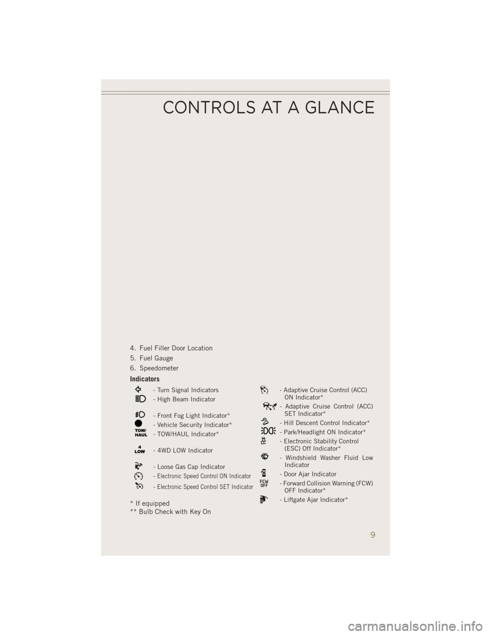
Indicators
- Turn Signal Indicators- Adaptive Cruise Control (ACC)ON Indicator*
- High Beam Indicator- Adaptive Cruise Control (ACC)SET Indicator*
- Front Fog Light Indicator*- Hill Descent Control Indicator*- Vehicle Security Indicator*- Park/Headlight ON Indicator*- TOW/HAUL Indicator*- Electronic Stability Control(ESC) Off Indicator*
- 4WD LOW Indicator- Windshield Washer Fluid LowIndicator
- Loose Gas Cap Indicator- Door Ajar Indicator-Electronic Speed Control ON Indicator- Forward Collision Warning (FCW)OFF Indicator*-Electronic Speed Control SET Indicator
- Liftgate Ajar Indicator** If equipped
** Bulb Check with Key On
CONTROLS AT A GLANCE
9
Page 32 of 204
TILT/TELESCOPING STEERING COLUMN
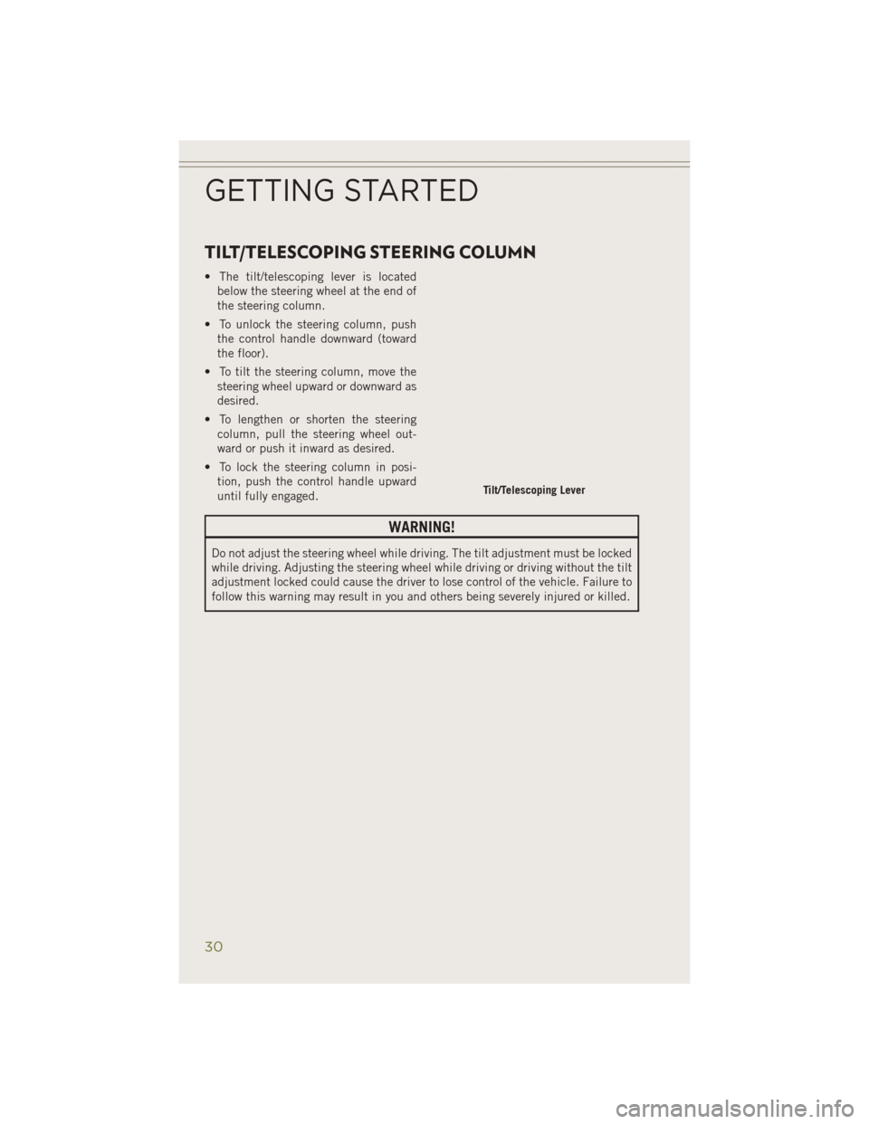
• The tilt/telescoping lever is locatedbelow the steering wheel at the end of
the steering column.
• To unlock the steering column, push the control handle downward (toward
the floor).
• To tilt the steering column, move the steering wheel upward or downward as
desired.
• To lengthen or shorten the steering column, pull the steering wheel out-
ward or push it inward as desired.
• To lock the steering column in posi- tion, push the control handle upward
until fully engaged.
WARNING!
Do not adjust the steering wheel while driving. The tilt adjustment must be locked
while driving. Adjusting the steering wheel while driving or driving without the tilt
adjustment locked could cause the driver to lose control of the vehicle. Failure to
follow this warning may result in you and others being severely injured or killed.
Tilt/Telescoping Lever
GETTING STARTED
30
Page 33 of 204
ENGINE BREAK-IN RECOMMENDATIONS
A long break-in period is not required for the engine and drivetrain (transmission and
axle) in your vehicle.
Drive moderately during the first 300 miles (500 km). After the initial 60 miles
(100 km), speeds up to 50 or 55 mph (80 or 90 km/h) are desirable.
While cruising, brief full-throttle acceleration within the limits of local traffic laws
contributes to a good break-in. Wide-open throttle acceleration in low gear can be
detrimental and should be avoided.
The engine oil installed in the engine at the factory is a high-quality energy
conserving type lubricant. Oil changes should be consistent with anticipated climate
conditions under which vehicle operations will occur. For the recommended viscosity
and quality grades, refer to “Maintaining Your Vehicle.”
NOTE:
A new engine may consume some oil during its first few thousand miles (kilometers)
of operation. This should be considered a normal part of the break-in and not
interpreted as an indication of an engine problem or malfunction.
CAUTION!
Never use Non-Detergent Oil or Straight Mineral Oil in the engine or damage may result.
TURN SIGNAL/HIGH BEAM LEVER
Turn Signals/Lane Change Assist
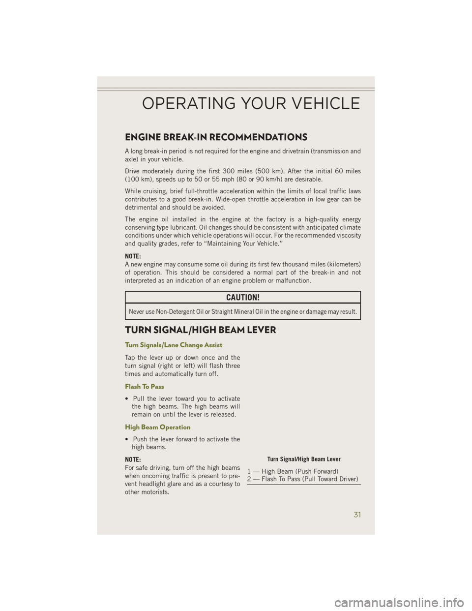
Tap the lever up or down once and the
turn signal (right or left) will flash three
times and automatically turn off.
Flash To Pass
• Pull the lever toward you to activatethe high beams. The high beams will
remain on until the lever is released.
High Beam Operation
• Push the lever forward to activate thehigh beams.
NOTE:
For safe driving, turn off the high beams
when oncoming traffic is present to pre-
vent headlight glare and as a courtesy to
other motorists.
Turn Signal/High Beam Lever
1 — High Beam (Push Forward)
2 — Flash To Pass (Pull Toward Driver)
OPERATING YOUR VEHICLE
31
Page 35 of 204
Ambient Light Dimmer
• Rotate the left dimmer control upward or downward to increase or decrease thebrightness of the ambient light located in the overhead console, door handle lights,
under I/P lights, door map pocket lights, and cubby bin lights.
• Rotate the left dimmer control to the extreme bottom position to turn off the ambient lights.
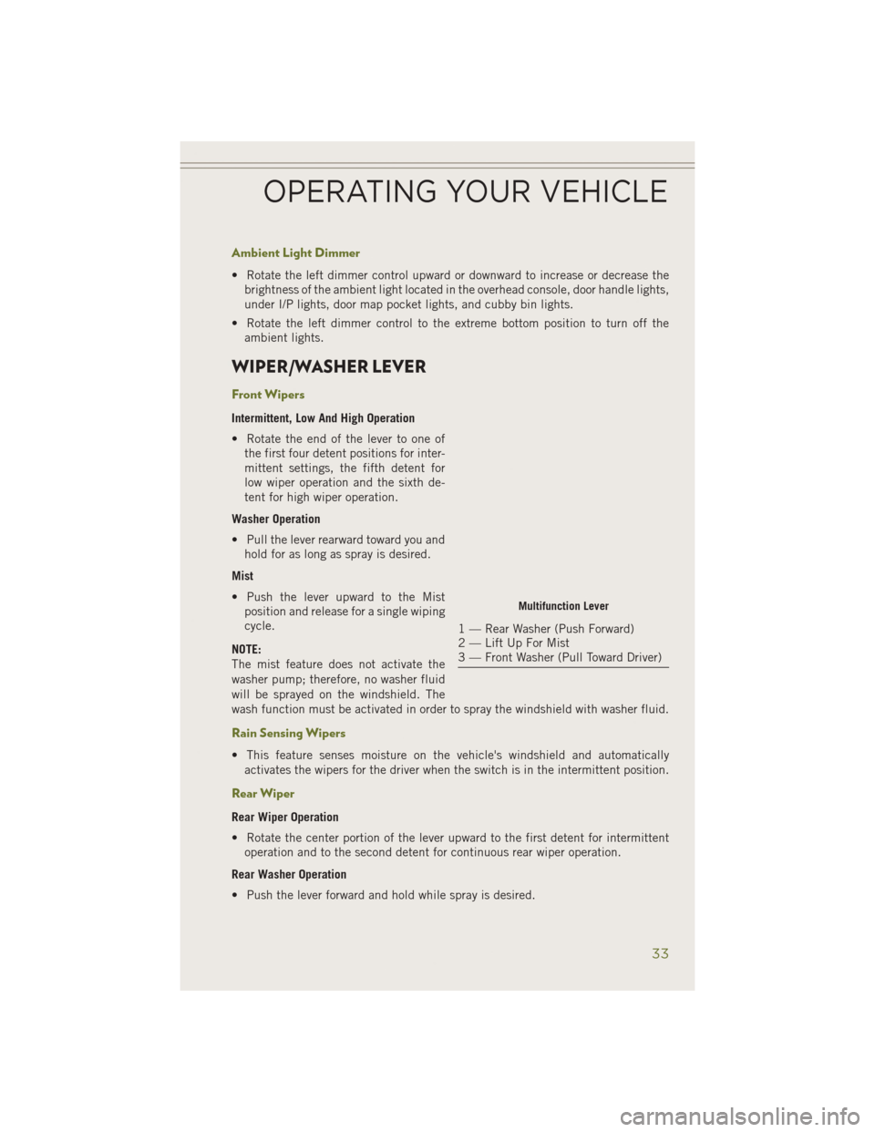
WIPER/WASHER LEVER
Front Wipers
Intermittent, Low And High Operation
• Rotate the end of the lever to one ofthe first four detent positions for inter-
mittent settings, the fifth detent for
low wiper operation and the sixth de-
tent for high wiper operation.
Washer Operation
• Pull the lever rearward toward you and hold for as long as spray is desired.
Mist
• Push the lever upward to the Mist position and release for a single wiping
cycle.
NOTE:
The mist feature does not activate the
washer pump; therefore, no washer fluid
will be sprayed on the windshield. The
wash function must be activated in order to spray the windshield with washer fluid.
Rain Sensing Wipers
• This feature senses moisture on the vehicle's windshield and automatically activates the wipers for the driver when the switch is in the intermittent position.
Rear Wiper
Rear Wiper Operation
• Rotate the center portion of the lever upward to the first detent for intermittentoperation and to the second detent for continuous rear wiper operation.
Rear Washer Operation
• Push the lever forward and hold while spray is desired.
Multifunction Lever
1 — Rear Washer (Push Forward)
2 — Lift Up For Mist
3 — Front Washer (Pull Toward Driver)
OPERATING YOUR VEHICLE
33
Page 40 of 204
WARNING!
• Adaptive Cruise Control (ACC) is a convenience system. It is not a substitute foractive driving involvement. It is always the driver’s responsibility to be attentive
of road, traffic, and weather conditions, vehicle speed, distance to the vehicle
ahead; and, most importantly, brake operation to ensure safe operation of the
vehicle under all road conditions. Your complete attention is always required
while driving to maintain safe control of your vehicle. Failure to follow these
warnings can result in a collision and death or serious personal injury.
• The ACC system:
• Does not react to pedestrians, oncoming vehicles, and stationary objects
(e.g., a stopped vehicle in a traffic jam or a disabled vehicle).
• Cannot take street, traffic, and weather conditions into account, and may
be limited upon adverse sight distance conditions.
• Does not always fully recognize complex driving conditions, which can
result in wrong or missing distance warnings.
• Can only apply a maximum of 40% of the vehicle’s braking capability,
and will not bring the vehicle to a complete stop.
You should switch off the ACC system:
• When driving in fog, heavy rain, heavy snow, sleet, heavy traffic, and complex
driving situations (i.e., in highway construction zones).
• When entering a turn lane or highway off ramp; when driving on roads that are
winding, icy, snow-covered, slippery, or have steep uphill or downhill slopes.
• When towing a trailer up or down steep slopes.
• When circumstances do not allow safe driving at a constant speed.
OPERATING YOUR VEHICLE
38
Page 50 of 204
WARNING!
• Drivers must be careful when backing up even when using ParkSense®. Always
check carefully behind your vehicle, look behind you, and be sure to check for
pedestrians, animals, other vehicles, obstructions, and blind spots before
backing up. You are responsible for safety and must continue to pay attention
to your surroundings. Failure to do so can result in serious injury or death.
• Before using ParkSense
®, it is strongly recommended that the ball mount and
hitch ball assembly is disconnected from the vehicle when the vehicle is not
used for towing. Failure to do so can result in injury or damage to vehicles or
obstacles because the hitch ball will be much closer to the obstacle than the
rear fascia when the loudspeaker sounds the continuous tone. Also, the sensors
could detect the ball mount and hitch ball assembly, depending on its size and
shape, giving a false indication that an obstacle is behind the vehicle.
LANESENSE
The LaneSense system can be enabled and disabled with the LaneSense button,
located on the switch panel below the Uconnect®display.
• Press the LaneSense button to turn the system ON (LED turns off).
The LaneSense system is operational at
speeds above 37 mph (60 km/h) and
below 112 mph (180 km/h). The La-
neSense system uses a forward looking
camera to detect lane markings and mea-
sure vehicle position within the lane
boundaries.
When both lane markings are detected
and the driver unintentionally drifts out
of the lane (no turn signal applied), the
LaneSense system provides a haptic
warning in the form of torque applied to
the steering wheel to prompt the driver to
remain within the lane boundaries. If the driver continues to unintentionally drift out
of the lane, the LaneSense system provides a visual warning through the instrument
cluster to prompt the driver to remain within the lane boundaries.
LaneSense Button
OPERATING YOUR VEHICLE
48
Page 66 of 204
Built-In Features (Uconnect® 8.4A And 8.4AN Only)
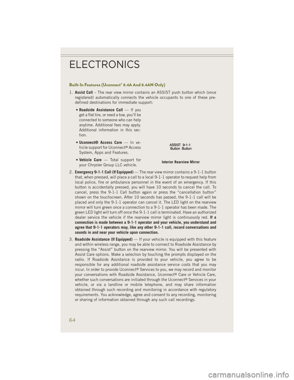
1.Assist Call – The rear view mirror contains an ASSIST push button which (once
registered) automatically connects the vehicle occupants to one of these pre-
defined destinations for immediate support:
• Roadside Assistance Call —
If you
get a flat tire, or need a tow, you’ll be
connected to someone who can help
anytime. Additional fees may apply.
Additional information in this sec-
tion.
• Uconnect® Access Care —Inve-
hicle support for Uconnect®Access
System, Apps and Features.
• Vehicle Care — Total support for
your Chrysler Group LLC vehicle.
2. Emergency 9-1-1 Call (If Equipped) — The rear view mirror contains a 9-1-1 button
that, when pressed, will place a call to a local 9-1-1 operator to request help from
local police, fire or ambulance personnel in the event of an emergency. If this
button is accidentally pressed, you will have 10 seconds to cancel the call. To
cancel, press the 9-1-1 Call button again or press the “cancellation button”
shown on the touchscreen. After 10 seconds has passed, the 9-1-1 call will be
placed and only the 9-1-1 operator can cancel it. The LED light on the rearview
mirror will turn green once a connection to a 9-1-1 operator has been made. The
green LED light will turn off once the 9-1-1 call is terminated. Have an authorized
dealer service the vehicle if the rearview mirror light is continuously red. If a
connection is made between a 9-1-1 operator and your vehicle, you understand and
agree that 9-1-1 operators may, like any other 9-1-1 call, record conversations and
sounds in and near your vehicle upon connection.
3. Roadside Assistance (If Equipped) — If your vehicle is equipped with this feature
and within wireless range, you may be able to connect to Roadside Assistance by
pressing the “Assist” button on the rearview mirror. You will be presented with
Assist Care options. Make a selection by touching the prompts displayed on the
radio. If Roadside Assistance is provided to your vehicle, you agree to be
responsible for any additional roadside assistance service costs that you may
incur. In order to provide Uconnect
®Services to you, we may record and monitor
your conversations with Roadside Assistance, Uconnect®Care or Vehicle Care,
whether such conversations are initiated through the Uconnect®Services in your
vehicle, or via a landline or mobile telephone, and may share information
obtained through such recording and monitoring in accordance with regulatory
requirements. You acknowledge, agree and consent to any recording, monitoring
or sharing of information obtained through any such call recordings.
Interior Rearview Mirror
ELECTRONICS
64
Page 120 of 204
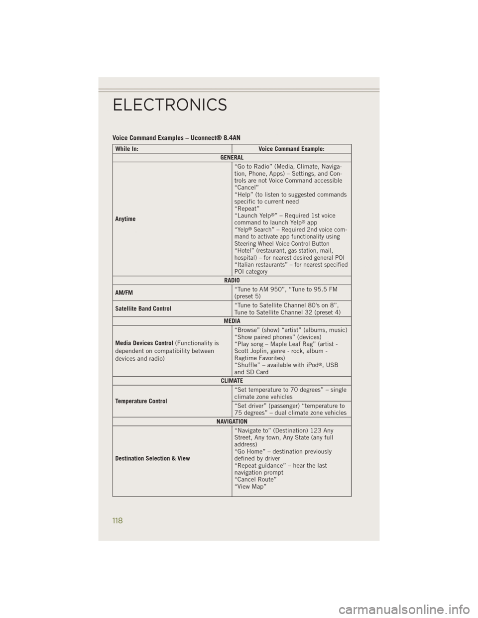
Voice Command Examples – Uconnect® 8.4AN
While In:Voice Command Example:
GENERAL
Anytime “Go to Radio” (Media, Climate, Naviga-
tion, Phone, Apps) – Settings, and Con-
trols are not Voice Command accessible
“Cancel”
“Help” (to listen to suggested commands
specific to current need
“Repeat”
“Launch Yelp
®” – Required 1st voice
command to launch Yelp®app“Yelp®Search” – Required 2nd voice com-
mand to activate app functionality using
Steering Wheel Voice Control Button
“Hotel” (restaurant, gas station, mail,
hospital) – for nearest desired general POI
“Italian restaurants” – for nearest specified
POI category
RADIO
AM/FM “Tune to AM 950”, “Tune to 95.5 FM
(preset 5)
Satellite Band Control “Tune to Satellite Channel 80's on 8”,
Tune to Satellite Channel 32 (preset 4)
MEDIA
Media Devices Control (Functionality is
dependent on compatibility between
devices and radio) “Browse” (show) “artist” (albums, music)
“Show paired phones” (devices)
“Play song – Maple Leaf Rag” (artist -
Scott Joplin, genre - rock, album -
Ragtime Favorites)
“Shuffle” – available with iPod
®, USB
and SD Card
CLIMATE
Temperature Control “Set temperature to 70 degrees” – single
climate zone vehicles
“Set driver” (passenger) “temperature to
75 degrees” – dual climate zone vehicles
NAVIGATION
Destination Selection & View “Navigate to” (Destination) 123 Any
Street, Any town, Any State (any full
address)
“Go Home” – destination previously
defined by driver
“Repeat guidance” – hear the last
navigation prompt
“Cancel Route”
“View Map”
ELECTRONICS
118
Page 131 of 204
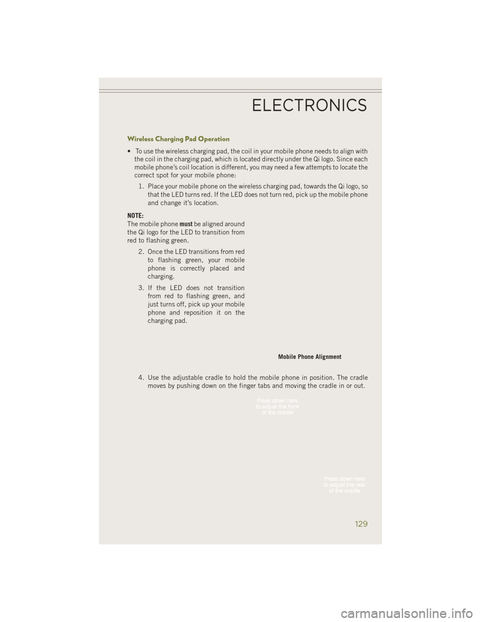
Wireless Charging Pad Operation
• To use the wireless charging pad, the coil in your mobile phone needs to align withthe coil in the charging pad, which is located directly under the Qi logo. Since each
mobile phone’s coil location is different, you may need a few attempts to locate the
correct spot for your mobile phone:
1. Place your mobile phone on the wireless charging pad, towards the Qi logo, so that the LED turns red. If the LED does not turn red, pick up the mobile phone
and change it’s location.
NOTE:
The mobile phone mustbe aligned around
the Qi logo for the LED to transition from
red to flashing green.
2. Once the LED transitions from redto flashing green, your mobile
phone is correctly placed and
charging.
3. If the LED does not transition from red to flashing green, and
just turns off, pick up your mobile
phone and reposition it on the
charging pad.
4. Use the adjustable cradle to hold the mobile phone in position. The cradle moves by pushing down on the finger tabs and moving the cradle in or out.
Mobile Phone Alignment
ELECTRONICS
129