Push to start button JEEP CHEROKEE 2015 KL / 5.G Owner's Guide
[x] Cancel search | Manufacturer: JEEP, Model Year: 2015, Model line: CHEROKEE, Model: JEEP CHEROKEE 2015 KL / 5.GPages: 772, PDF Size: 18.21 MB
Page 417 of 772
NOTE:If the vehicle is programmed 1st Press Of Key Fob
Unlocks “All Doors,” all doors will unlock no matter
which Passive Entry equipped door handle is grasped. If
1st Press Of Key Fob Unlocks “Driver Door” is pro-
grammed, only the driver ’s door will unlock when the
driver ’s door is grasped. With Passive Entry, if 1st Press
Of Key Fob Unlocks “Driver Door” is programmed,
touching the handle more than once will only result in
the driver ’s door opening. If “Driver Door” is selected,
once the driver door is opened, the interior door lock/
unlock switch can be used to unlock all doors (or use
RKE transmitter).
•Passive Entry
This feature allows you to lock and unlock the vehicles
door(s) without having to press the Remote Keyless
Entry (RKE) transmitter lock or unlock buttons. To make
your selection, press the “Passive Entry” button on the
touchscreen, until a check-mark appears next to setting,
showing that setting has been selected. Press the back
arrow button on the touchscreen to return to the previous
menu, or push the back button on the faceplate. Refer to
“Keyless Enter-N-Go™” in “Things To Know Before
Starting Your Vehicle”.
•Personal Settings Linked to Key Fob — If Equipped
This feature provides automatic recall of all settings
stored to a memory location (driver ’s seat, exterior
mirrors, steering column position and radio station pre-
sets) to enhance driver mobility when entering and
exiting the vehicle. To make your selection, press the
“Personal Settings Linked to Key Fob” button on the
touchscreen, until a check-mark appears next to setting,
showing that setting has been selected. Press the back
arrow button on the touchscreen to return to the previous
menu, or push the back button on the faceplate.
4
UNDERSTANDING YOUR INSTRUMENT PANEL 415
Page 418 of 772
NOTE:The seat will return to the memorized seat
location (if Recall Memory with Remote Key Unlock is set
to ON) when the Remote Keyless Entry (RKE) transmitter
is used to unlock the door. Refer to “Driver Memory
Seat” in “Understanding The Features Of Your Vehicle”
for further information.
•Power Lift Gate Chime — If Equipped
This feature plays an alert when the power lift gate is
raising or lowering. To make your selection, press the
“Power Lift Gate Chime” button on the touchscreen, until
a check-mark appears next to setting, showing that
setting has been selected. Press the back arrow button on
the touchscreen to return to the previous menu, or push
the back button on the faceplate.
Auto-On Comfort — If Equipped
After pressing the “Auto-On Comfort” button on the
touchscreen the following settings will be available:
•Auto-On Driver Heated/Ventilated Seat & Steering
Wheel With Vehicle Start — If Equipped
When this feature is selected the driver’s heated seat will
automatically turn on when temperatures are below 40° F
(4.4° C). When temperatures are above 80° F (26.7° C) the
driver vented seat will turn on. To make your selection,
press the “Auto-On Driver Heated/Ventilated Seat &
Steering Wheel With Vehicle Start” button on the touch-
screen, then select either “Off,” “Remote Start” or “All
Starts” until a check-mark appears next to setting, show-
ing that setting has been selected. Press the back arrow/
Done button on the touchscreen to return to the previous
menu.
Engine Off Options
After pressing the Engine Off Options button on the
touchscreen the following settings will be available.
416 UNDERSTANDING YOUR INSTRUMENT PANEL
Page 431 of 772
Mix Mode
Air is directed through the floor, defrost and side
window demist outlets. This setting works best in
cold or snowy conditions that require extra heat at the
windshield. This setting is good for maintaining comfort,
while reducing moisture on the windshield.
Defrost Mode
Air is directed through the windshield and side
window demist outlets. Use the DEFROST mode
with maximum blower and warm temperature settings
for best windshield and side window defrosting.
NOTE:The air conditioning compressor operates in MIX
and DEFROST, or a blend of these modes even if the A/C
button is not pushed. This dehumidifies the air to help
dry the windshield. To improve fuel economy, use these
modes only when necessary.
Recirculation Control
Push this button to choose between outside air intake or
recirculation of the air inside the vehicle. A LED will
illuminate when you are in Recirculation mode. Only use
the Recirculation mode to temporarily block out any
outside odors, smoke, or dust, and to cool the interior
rapidly upon initial start-up in very hot or humid
weather.
NOTE:
•If the RECIRCULATION button is pushed when the
system is in Defrost mode the Recirculation LED
indicator will flash three times and then turn off to
indicate Recirculation mode is not allowed.
•Continuous use of the Recirculation mode may make
the inside air stuffy and window fogging may occur.
Extended use of this mode is not recommended.
4
UNDERSTANDING YOUR INSTRUMENT PANEL 429
Page 432 of 772
•In cold or damp weather, the use of the Recirculation
mode will cause windows to fog on the inside because
of moisture buildup inside the vehicle. For maximum
defogging, select the outside air position.
•The A/C can be deselected manually without disturb-
ing the mode control selection by pushing the A/C
button.
Air Outlets
The airflow from each of the instrument panel outlets can
be adjusted for direction, and turned on or off to control
airflow.
NOTE:For maximum airflow to the rear, the center
instrument panel outlets can be directed toward the rear
seat passengers.
Economy Mode
If ECONOMY mode is desired, push the A/C button to
turn off the LED indicator and the A/C compressor.
Rotate the temperature control knob to the desired tem-
perature. Also, make sure to select only Panel, Bi-Level or
Floor modes.
Windshield Wiper De-icer — If Equipped
The windshield wiper de-icer is a heating element lo-
cated at the base of the windshield.
The windshield wiper de-icer operates automatically
once the following conditions are met:
•Activation By Front Defrost
The wiper de-icer activates automatically during a cold
weather manual start withfull defrost,theblower speed
is greater than five,and when theambient temperature
is below 40° F (4.4° C).
430 UNDERSTANDING YOUR INSTRUMENT PANEL
Page 447 of 772
The windshield wiper de-icer operates automatically
once the following conditions are met:
•Activation By Front Defrost
The wiper de-icer activates automatically during a cold
weather manual start withfull defrost,theblower speed
is greater than five,and when theambient temperature
is below 40° F (4.4° C).
•Activation By Rear Defrost
The wiper de-icer activates automatically when the Rear
Defrost is operating and theambient temperature is
below 40° F (4.4° C).
•Activation By Remote Start Operation
When the Remote Start is activated and theoutside
ambient temperature is less than 40° F (4.4° C)the
windshield wiper de-icer is activated. Upon exiting Re-
mote Start, the climate control functions will resume their
previous operation except, if the de-icer is active, the
de-icer timer and operation will continue.
Automatic Temperature Control (ATC)
Automatic Operation
1. Push the AUTO button on the faceplate or press the
“AUTO” button on the touchscreen.
2. Next, adjust the temperature you would like the
system to maintain by adjusting the driver and pas-
senger temperature buttons on the faceplate or but-
tons on the touchscreen. Once the desired temperature
is displayed, the system will achieve and automati-
cally maintain that comfort level.
4
UNDERSTANDING YOUR INSTRUMENT PANEL 445
Page 453 of 772
If you see theicon on your touchscreen, you have
the Uconnect® 8.4AN system. If not, you have a
Uconnect® 8.4A system.
Get Started
All you need to control your Uconnect® system with
your voice are the buttons on your steering wheel.
1. VisitUconnectPhone.com to check mobile device
and feature compatibility and to find phone pair-
ing instructions.
2. Reduce background noise. Wind and passenger con-
versations are examples of noise that may impact
recognition.
3. Speak clearly at a normal pace and volume while
facing straight ahead. The microphone is positioned
on the rearview mirror and aimed at the driver.
4. Each time you give a Voice Command, you must first
push either the VR or Phone button, wait untilafter
the beep, then say your Voice Command.
5. You can interrupt the help message or system prompts
by pushing the VR or Phone button and saying a Voice
Command from current category.
4
UNDERSTANDING YOUR INSTRUMENT PANEL 451
Page 460 of 772
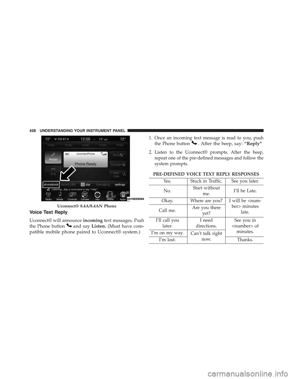
Voice Text Reply
Uconnect® will announceincomingtext messages. Push
the Phone buttonand sayListen.(Must have com-
patible mobile phone paired to Uconnect® system.)
1. Once an incoming text message is read to you, push
the Phone button. After the beep, say:“Reply”
2. Listen to the Uconnect® prompts. After the beep,
repeat one of the pre-defined messages and follow the
system prompts.
PRE-DEFINED VOICE TEXT REPLY RESPONSES
Yes. Stuck in Traffic. See you later.
No.Start without
me.I’ll be Late.
Okay. Where are you? I will be
late.Call me.Are you there
yet?
I’ll call you
later.
I need
directions.
See you in
minutes.I’m on my way.Can’t talk right
now.I’m lost.Thanks.
Uconnect® 8.4A/8.4AN Phone
458 UNDERSTANDING YOUR INSTRUMENT PANEL
Page 462 of 772
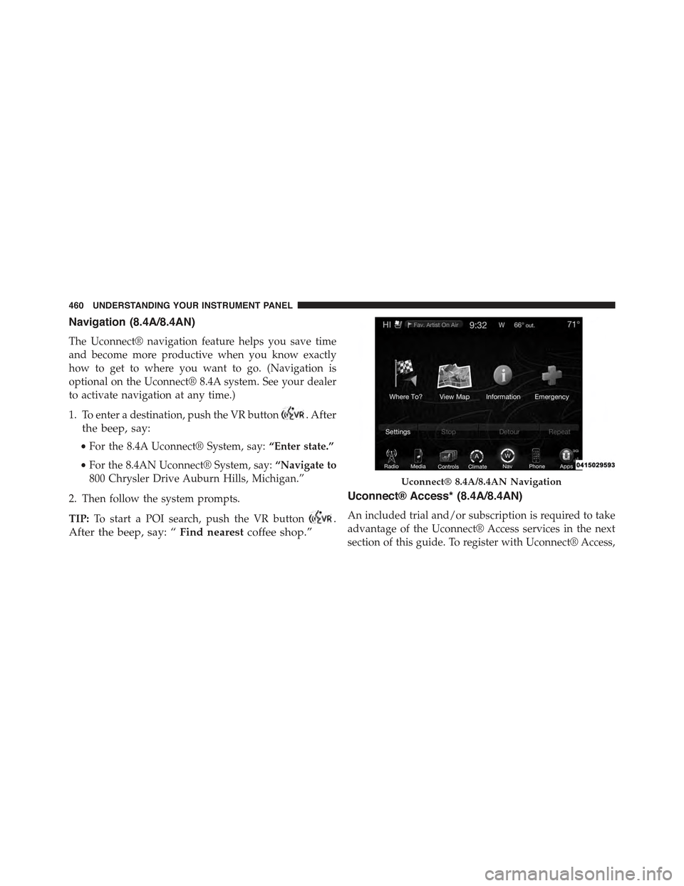
Navigation (8.4A/8.4AN)
The Uconnect® navigation feature helps you save time
and become more productive when you know exactly
how to get to where you want to go. (Navigation is
optional on the Uconnect® 8.4A system. See your dealer
to activate navigation at any time.)
1. To enter a destination, push the VR button. After
the beep, say:
•For the 8.4A Uconnect® System, say:“Enter state.”
•For the 8.4AN Uconnect® System, say:“Navigate to
800 Chrysler Drive Auburn Hills, Michigan.”
2. Then follow the system prompts.
TIP:To start a POI search, push the VR button.
After the beep, say: “Find nearestcoffee shop.”
Uconnect® Access* (8.4A/8.4AN)
An included trial and/or subscription is required to take
advantage of the Uconnect® Access services in the next
section of this guide. To register with Uconnect® Access,
Uconnect® 8.4A/8.4AN Navigation
460 UNDERSTANDING YOUR INSTRUMENT PANEL
Page 591 of 772
NOTE:When removing the fuel filler cap, lay the cap
tether in the hook, located on the fuel filler door rein-
forcement.
1. Press the fuel filler door release switch (located on the
driver ’s side door trim).
2. Open the fuel filler door, and remove the fuel filler
cap.
NOTE:
•In certain cold conditions, ice may prevent the fuel
door from opening. If this occurs, lightly push on the
fuel door to break the ice buildup and re-release the
fuel door using the inside release button. Do not pry
on the door.
•When the fuel nozzle “clicks” or shuts off, the fuel tank
is full.
•Tighten the gas cap about one quarter turn until you
hear one click. This is an indication that the cap is
properly tightened.
•If the gas cap is not tightened properly, the MIL will
come on. Be sure the gas cap is tightened every time
the vehicle is refueled.
CAUTION!
•Damage to the fuel system or emission control
system could result from using an improper fuel
cap (gas cap). A poorly fitting cap could let impu-
rities into the fuel system. Also, a poorly fitting
aftermarket cap can cause the “Malfunction Indi-
cator Light (MIL)” to illuminate, due to fuel vapors
escaping from the system.
•A poorly fitting gas cap may cause the MIL to turn
on.
(Continued)
5
STARTING AND OPERATING 589
Page 625 of 772
on the ground. This will provide the best positioning
of the kit when injecting the sealant into the deflated
tire and running the air pump. Move the vehicle as
necessary to place the valve stem in this position
before proceeding.
3. Place the transmission in PARK (auto transmission) or
in Gear (manual transmission) and turn Off the igni-
tion.
4. Set the parking brake.
(B) Setting Up To Use Tire Service Kit:
1. Push in the Mode Select Knob (5) and turn to the
Sealant Mode position.
2. Uncoil the Sealant Hose (6) and then remove the cap
from the fitting at the end of the hose.
3. Place the Tire Service Kit flat on the ground next to the
deflated tire.
4. Remove the cap from the valve stem and then screw
the fitting at the end of the Sealant Hose (6) onto the
valve stem.
5. Uncoil the Power Plug (8) and insert the plug into the
vehicle’s 12 Volt power outlet.
NOTE:Do not remove foreign objects (e.g., screws or
nails) from the tire.
(C) Injecting Tire Service Kit Sealant Into The
Deflated Tire:
•Always start the engine before turning ON the Tire
Service Kit.
NOTE:Manual transmission vehicles must have the
parking brake engaged and the shift lever in NEUTRAL.
•After pressing the Power Button (4), the sealant (white
fluid) will flow from the Sealant Bottle (1) through the
Sealant Hose (6) and into the tire.
6
WHAT TO DO IN EMERGENCIES 623