seats JEEP CHEROKEE 2015 KL / 5.G User Guide
[x] Cancel search | Manufacturer: JEEP, Model Year: 2015, Model line: CHEROKEE, Model: JEEP CHEROKEE 2015 KL / 5.GPages: 244, PDF Size: 30.6 MB
Page 3 of 244
INTRODUCTION/WELCOME
WELCOME FROM CHRYSLERGROUP LLC.................. 3
CONTROLS AT A GLANCE
DRIVER COCKPIT.............. 6INSTRUMENT CLUSTER.......... 8
GETTING STARTED
KEY FOB . . . . . . . . . . . . . . . . . . . 10REMOTE START............... 12VEHICLE SECURITY ALARM....... 13KEYLESS ENTER-N-GO™......... 13SEAT BELT SYSTEMS........... 17SUPPLEMENTAL RESTRAINT SYSTEM(SRS) — AIR BAGS............ 18CHILD RESTRAINTS............ 24HEAD RESTRAINTS............. 29FRONT SEATS................ 31REAR SEATS................ 34HEATED/VENTILATED SEATS....... 35HEATED STEERING WHEEL....... 36TILT/TELESCOPING STEERINGCOLUMN................... 37
OPERATING YOUR VEHICLE
ENGINE BREAK-INRECOMMENDATIONS........... 38TURN SIGNAL/HIGH BEAM LEVER . . . 38HEADLIGHT SWITCH............ 39WIPER/WASHER LEVER.......... 40ELECTRONIC SPEED CONTROL..... 41ADAPTIVE CRUISE CONTROL (ACC) . . . 44FORWARD COLLISION WARNING (FCW)WITH MITIGATION . . . . . . . . . . . . . 47MANUAL CLIMATE CONTROLSWITHOUT TOUCHSCREEN........ 49MANUAL CLIMATE CONTROLSWITH TOUCHSCREEN........... 50AUTOMATIC TEMPERATURECONTROLS (ATC).............. 53STOP/START SYSTEM — 3.2L ENGINE . . 57ELECTRIC PARKING BRAKE (EPB) . . . 59PA R K S E N S E®................ 61PARKVIEW®REAR BACK-UP CAMERA.. 63POWER SUNROOF............. 64WIND BUFFETING............. 67
ELECTRONICS
YOUR VEHICLE'S SOUND SYSTEM . . . 68IDENTIFYING YOUR RADIO........ 70Uconnect®ACCESS............. 71Uconnect®5.0 . . . . . . . . . . . . . . . . 88
Uconnect®8.4A . . . . . . . . . . . . . . 100Uconnect®8.4AN . . . . . . . . . . . . . 133STEERING WHEEL AUDIOCONTROLS................. 151ELECTRONIC VEHICLE INFORMATIONCENTER (EVIC) AND DRIVERINFORMATION DISPLAY (DID)..... 151PROGRAMMABLE FEATURES...... 153UNIVERSAL GARAGE DOOR OPENER(HomeLink®)................154POWER INVERTER............ 156POWER OUTLET............. 157WIRELESS CHARGING PAD....... 159
OFF-ROAD CAPABILITIES
FOUR-WHEEL DRIVE OPERATION . . . 162SELEC-TERRAIN™............ 165
UTILITY
CARGO AREA FEATURES........ 166TRAILER TOWING WEIGHTS (MAXIMUMTRAILER WEIGHT RATINGS)...... 167RECREATIONAL TOWING (BEHINDMOTORHOME, ETC.)........... 168
WHAT TO DO IN EMERGENCIES
ROADSIDE ASSISTANCE......... 173INSTRUMENT CLUSTER WARNINGLIGHTS................... 173INSTRUMENT CLUSTER INDICATORLIGHTS................... 179IF YOUR ENGINE OVERHEATS..... 182TIRE SERVICE KIT . . . . . . . . . . . . 183JACKING AND TIRE CHANGING.... 189JUMP-STARTING............. 194FREEING A STUCK VEHICLE...... 197RECOVERY STRAP............ 198SHIFT LEVER OVERRIDE........ 198TOWING A DISABLED VEHICLE.... 199EVENT DATA RECORDER (EDR).... 200
MAINTAINING YOUR VEHICLE
OPENING THE HOOD.......... 201ENGINE COMPARTMENT........ 202FLUID CAPACITIES............ 206FLUIDS, LUBRICANTS AND GENUINEPA RT S . . . . . . . . . . . . . . . . . . . . 2 0 6MAINTENANCE PROCEDURES..... 208MAINTENANCE SCHEDULE...... 208FUSES.................... 213TIRE PRESSURES............. 219SPARE TIRES — IF EQUIPPED..... 219WHEEL AND WHEEL TRIM CARE . . . 221REPLACEMENT BULBS......... 222
TABLE OF CONTENTS
Page 25 of 244
The following requirements must be strictly followed:
• Do not modify the front passenger seat assembly or components in any way.
• Do not use prior or future model year seat covers or cushions not designated by
Chrysler Group LLC for the specific model being repaired. Always use the correct
seat cover and cushion specified for the vehicle.
• Do not replace the seat cover or cushion with an aftermarket seat cover or cushion.
• Do not add a secondary seat cover or mat.
• At no time should any Supplemental Restraint System (SRS) component or SRS
related component or fastener be modified or replaced with any part except those
which are approved by Chrysler Group LLC.
Supplemental Knee Air Bags
This vehicle is equipped with a Supplemental Driver Knee Air Bag mounted in the
instrument panel below the steering column and a Supplemental Passenger Knee Air
Bag mounted in the instrument panel below the glove compartment. The Supple-
mental Knee Air Bags provide enhanced protection during a frontal impact by
working together with the seat belts, pretensioners, and Advanced Front Air Bags.
Supplemental Side Air Bags
• Your vehicle is equipped with Supplemental Seat-Mounted Side Air Bags (SABs)
located in the outboard side of the front and rear (in vehicles equipped with
outboard rear seat SABs) seats. The SABs are marked with a SRS AIRBAG label
sewn into the outboard side of the seats.
• Your vehicle is equipped with Supplemental Side Air Bag Inflatable Curtains
(SABICs) located above the side windows. The trim covering the SABICs is labeled
SRS AIRBAG. The SABICs may help reduce the risk of partial or complete ejection
of vehicle occupants through side windows in certain side impact events.
• The SABICs and SABs (“Side Air Bags”) are designed to activate in certain side
impacts and certain rollover events. The Occupant Restraint Controller (“ORC”)
determines whether the deployment of the Side Air Bags in a particular side
impact or rollover event is appropriate, based on the severity and type of collision.
Vehicle damage by itself is not a good indicator of whether or not Side Air Bags
should have deployed.
GETTING STARTED
23
Page 26 of 244
WARNING!
• Side Air Bags need room to inflate. Do not lean against the door or window. Sit
upright in the center of the seat.
• Being too close to the Side Air Bags during deployment could cause you to be
severely injured or killed.
• Relying on the Side Air Bags alone could lead to more severe injuries in a
collision. The Side Air Bags work with your seat belt to restrain you properly. In
some collisions, Side Air Bags won’t deploy at all. Always wear your seat belt
even though you have Side Air Bags.
• This vehicle is equipped with left and right Supplemental Side Air Bag
Inflatable Curtains (SABICs). Do not stack luggage or other cargo up high
enough to block the deployment of the SABICs. The trim covering above the
side windows where the SABIC and its deployment path are located should
remain free from any obstructions.
• This vehicle is equipped with SABICs. In order for the SABICs to work as
intended, do not install any accessory items in your vehicle which could alter
the roof. Do not add an aftermarket sunroof to your vehicle. Do not add roof
racks that require permanent attachments (bolts or screws) for installation on
the vehicle roof. Do not drill into the roof of the vehicle for any reason.
• Do not use accessory seat covers or place objects between you and the Side Air
Bags; the performance could be adversely affected and/or objects could be
pushed into you, causing serious injury.
CHILD RESTRAINTS
Children 12 years or younger should ride properly buckled up in a rear seat, if
available. According to crash statistics, children are safer when properly restrained in
the rear seats rather than in the front.
Every state in the United States and all Canadian provinces require that small
children ride in proper restraint systems. This is the law, and you can be prosecuted
for ignoring it.
NOTE:
•For additional information, refer towww.Seatcheck.org or call 1-866-SEATCHECK.
• Canadian residents should refer to Transport Canada’s website for additional
information:
http://www.tc.gc.ca/eng/motorvehiclesafety/safedrivers-childsafety-index-53.htm
GETTING STARTED
24
Page 31 of 244
WARNING!
• In a collision, an unrestrained child, even a tiny baby, can become a projectile
inside the vehicle. The force required to hold even an infant on your lap could
become so great that you could not hold the child, no matter how strong you
are. The child and others could be severely injured or killed. Any child riding in
your vehicle should be in a proper restraint for the child's size.
• Rearward-facing child seats must never be used in the front seat of a vehicle
with a front passenger air bag. An air bag deployment could cause severe injury
or death to infants in this position.
• Only use a rearward-facing child restraint in a vehicle with a rear seat.
• Improper installation of a child restraint to the LATCH anchorages can lead to
failure of an infant or child restraint. The child could be severely injured or
killed. Follow the manufacturer’s directions exactly when installing an infant or
child restraint.
• An incorrectly anchored tether strap could lead to increased head motion and
possible injury to the child. Use only the anchor positions directly behind the
child seat to secure a child restraint top tether strap.
• If your vehicle is equipped with a split rear seat, make sure the tether strap
does not slip into the opening between the seatbacks as you remove slack in
the strap.
HEAD RESTRAINTS
Head restraints are designed to reduce the risk of injury by restricting head
movement in the event of a rear impact. Head restraints should be adjusted so that
the top of the head restraint is located above the top of your ear.
WARNING!
The head restraints for all occupants must be properly adjusted prior to operating
the vehicle or occupying a seat. Head restraints should never be adjusted while the
vehicle is in motion. Driving a vehicle with the head restraints improperly adjusted
or removed could cause serious injury or death in the event of a collision.
GETTING STARTED
29
Page 32 of 244
Reactive Head Restraints — Front Seats
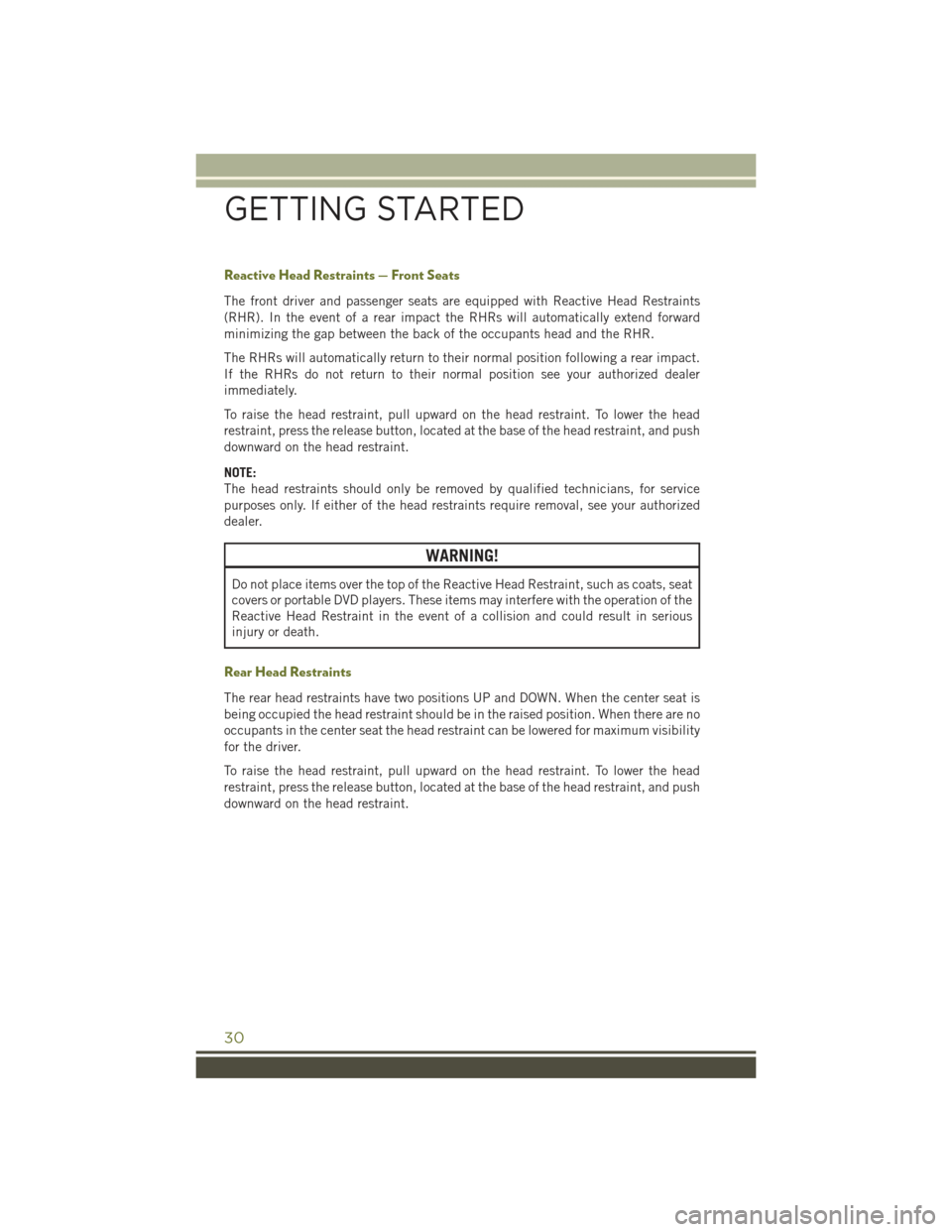
The front driver and passenger seats are equipped with Reactive Head Restraints
(RHR). In the event of a rear impact the RHRs will automatically extend forward
minimizing the gap between the back of the occupants head and the RHR.
The RHRs will automatically return to their normal position following a rear impact.
If the RHRs do not return to their normal position see your authorized dealer
immediately.
To raise the head restraint, pull upward on the head restraint. To lower the head
restraint, press the release button, located at the base of the head restraint, and push
downward on the head restraint.
NOTE:
The head restraints should only be removed by qualified technicians, for service
purposes only. If either of the head restraints require removal, see your authorized
dealer.
WARNING!
Do not place items over the top of the Reactive Head Restraint, such as coats, seat
covers or portable DVD players. These items may interfere with the operation of the
Reactive Head Restraint in the event of a collision and could result in serious
injury or death.
Rear Head Restraints
The rear head restraints have two positions UP and DOWN. When the center seat is
being occupied the head restraint should be in the raised position. When there are no
occupants in the center seat the head restraint can be lowered for maximum visibility
for the driver.
To raise the head restraint, pull upward on the head restraint. To lower the head
restraint, press the release button, located at the base of the head restraint, and push
downward on the head restraint.
GETTING STARTED
30
Page 33 of 244
FRONT SEATS
Power Seats
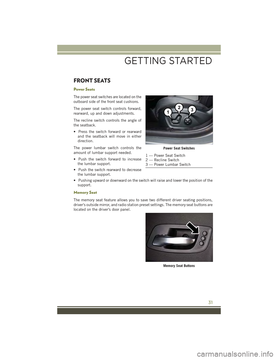
The power seat switches are located on the
outboard side of the front seat cushions.
The power seat switch controls forward,
rearward, up and down adjustments.
The recline switch controls the angle of
the seatback.
• Press the switch forward or rearward
and the seatback will move in either
direction.
The power lumbar switch controls the
amount of lumbar support needed.
• Push the switch forward to increase
the lumbar support.
• Push the switch rearward to decrease
the lumbar support.
• Pushing upward or downward on the switch will raise and lower the position of the
support.
Memory Seat
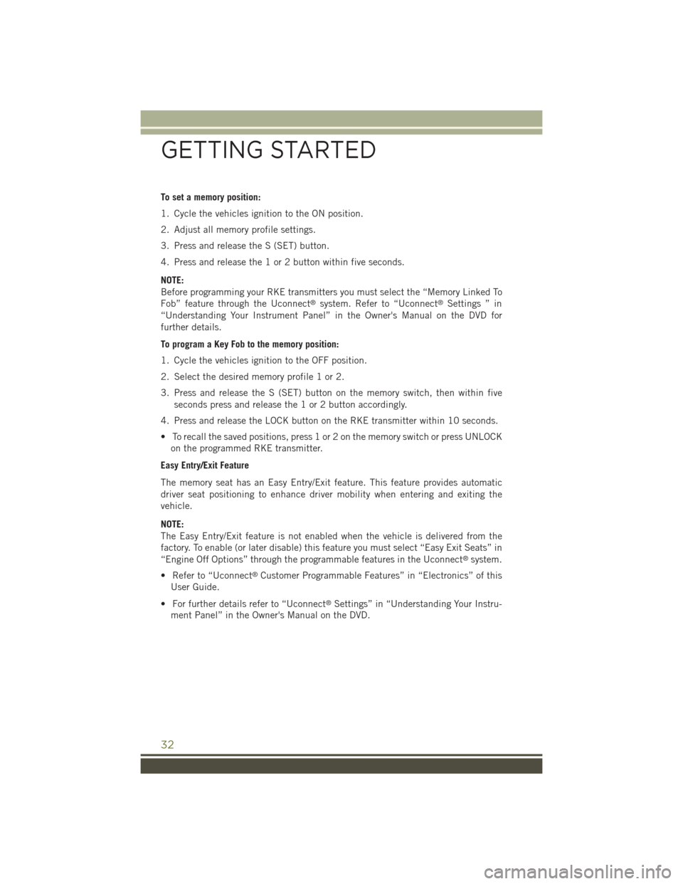
The memory seat feature allows you to save two different driver seating positions,
driver's outside mirror, and radio station preset settings. The memory seat buttons are
located on the driver's door panel.
Power Seat Switches
1 — Power Seat Switch2 — Recline Switch3 — Power Lumbar Switch
Memory Seat Buttons
GETTING STARTED
31
Page 34 of 244
To set a memory position:
1. Cycle the vehicles ignition to the ON position.
2. Adjust all memory profile settings.
3. Press and release the S (SET) button.
4. Press and release the 1 or 2 button within five seconds.
NOTE:
Before programming your RKE transmitters you must select the “Memory Linked To
Fob” feature through the Uconnect®system. Refer to “Uconnect®Settings ” in
“Understanding Your Instrument Panel” in the Owner's Manual on the DVD for
further details.
To program a Key Fob to the memory position:
1. Cycle the vehicles ignition to the OFF position.
2. Select the desired memory profile 1 or 2.
3. Press and release the S (SET) button on the memory switch, then within five
seconds press and release the 1 or 2 button accordingly.
4. Press and release the LOCK button on the RKE transmitter within 10 seconds.
• To recall the saved positions, press 1 or 2 on the memory switch or press UNLOCK
on the programmed RKE transmitter.
Easy Entry/Exit Feature
The memory seat has an Easy Entry/Exit feature. This feature provides automatic
driver seat positioning to enhance driver mobility when entering and exiting the
vehicle.
NOTE:
The Easy Entry/Exit feature is not enabled when the vehicle is delivered from the
factory. To enable (or later disable) this feature you must select “Easy Exit Seats” in
“Engine Off Options” through the programmable features in the Uconnect®system.
• Refer to “Uconnect®Customer Programmable Features” in “Electronics” of this
User Guide.
• For further details refer to “Uconnect®Settings” in “Understanding Your Instru-
ment Panel” in the Owner's Manual on the DVD.
GETTING STARTED
32
Page 36 of 244
REAR SEATS
60/40 Split Folding Rear Seat With Fold-Flat Feature
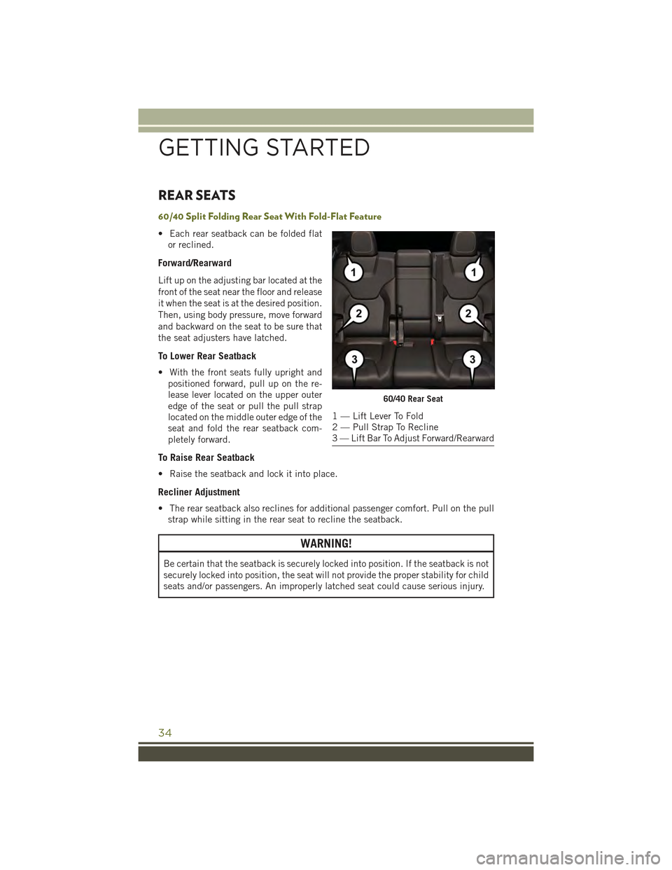
• Each rear seatback can be folded flat
or reclined.
Forward/Rearward
Lift up on the adjusting bar located at the
front of the seat near the floor and release
it when the seat is at the desired position.
Then, using body pressure, move forward
and backward on the seat to be sure that
the seat adjusters have latched.
To Lower Rear Seatback
• With the front seats fully upright and
positioned forward, pull up on the re-
lease lever located on the upper outer
edge of the seat or pull the pull strap
located on the middle outer edge of the
seat and fold the rear seatback com-
pletely forward.
To Raise Rear Seatback
• Raise the seatback and lock it into place.
Recliner Adjustment
• The rear seatback also reclines for additional passenger comfort. Pull on the pull
strap while sitting in the rear seat to recline the seatback.
WARNING!
Be certain that the seatback is securely locked into position. If the seatback is not
securely locked into position, the seat will not provide the proper stability for child
seats and/or passengers. An improperly latched seat could cause serious injury.
60/40 Rear Seat
1 — Lift Lever To Fold2 — Pull Strap To Recline3 — Lift Bar To Adjust Forward/Rearward
GETTING STARTED
34
Page 37 of 244
HEATED/VENTILATED SEATS
Front Heated Seats
The front heated seats control buttons are located within the climate or controls
screen of the touchscreen.
• Press the heated seat buttononce to turn the High setting On.
• Press the heated seat buttona second time to turn the Low setting On.
• Press the heated seat buttona third time to turn the heating elements Off.
If the High-level setting is selected, the system will automatically switch to Low-level
after approximately 60 minutes. The Low-level setting will turn Off automatically
after approximately 45 minutes.
NOTE:
Vehicle Equipped With Remote Start
On models that are equipped with remote start, this feature can be programmed to
come on during a remote start through the Uconnect®system. Refer to “Uconnect®
Settings” in “Understanding Your Instrument Panel” in the Owner's Manual on the
DVD.
WARNING!
• Persons who are unable to feel pain to the skin because of advanced age,
chronic illness, diabetes, spinal cord injury, medication, alcohol use, exhaus-
tion or other physical conditions must exercise care when using the seat heater.
It may cause burns even at low temperatures, especially if used for long periods
of time.
• Do not place anything on the seat that insulates against heat, such as a blanket
or cushion. This may cause the seat heater to overheat. Sitting in a seat that
has been overheated could cause serious burns due to the increased surface
temperature of the seat.
GETTING STARTED
35
Page 38 of 244
Front Ventilated Seats
Located in the seat cushion and seatback are small fans that draw the air from the
passenger compartment and pull air through fine perforations in the seat cover to
help keep the driver and front passenger cooler in higher ambient temperatures.
There are two ventilated seat control buttons located in the touchscreen that allow
the driver and passenger to operate the seats independently.
The ventilated seat buttons are used to control the speed of the fans located in the seat.
To operate the system, press the “Controls” button on touchscreen located on the
bottom of the Uconnect®display.
• Press the ventilated seat buttononce to choose HIGH.
• Press the ventilated seat buttona second time to choose LOW.
• Press the ventilated seat buttona third time to turn the ventilated seat OFF.
NOTE:
Vehicle Equipped With Remote Start
On models that are equipped with remote start, this feature can be programmed to come
on during a remote start through the Uconnect®system. Refer to “Uconnect®Settings”
in “Understanding Your Instrument Panel” in the Owner's Manual on the DVD.
HEATED STEERING WHEEL
The steering wheel contains a heating element that heats the steering wheel to one
temperature setting.
The heated steering wheel control button is located within the Uconnect®system.
You can gain access to the control buttons through the climate screen or the controls
screen.
• Press the heated steering wheel buttononce to turn the heating element ON.
• Press the heated steering wheel buttona second time to turn the heating
element OFF.
Once the heated steering wheel has been turned on, it will operate for up to
80 minutes before automatically shutting off. The heated steering wheel can shut off
early or may not turn on when the steering wheel is already warm.
NOTE:
Vehicle Equipped With Remote Start
On models that are equipped with remote start, this feature can be programmed to come
on during a remote start through the Uconnect®system. Refer to “Uconnect®Settings”
in “Understanding Your Instrument Panel” in the Owner's Manual on the DVD.
GETTING STARTED
36