tow JEEP CHEROKEE 2016 KL / 5.G Owner's Manual
[x] Cancel search | Manufacturer: JEEP, Model Year: 2016, Model line: CHEROKEE, Model: JEEP CHEROKEE 2016 KL / 5.GPages: 236, PDF Size: 11.24 MB
Page 183 of 236
WARNING!
A loose tire or jack thrown forward in a collision or hard stop could endanger the
occupants of the vehicle. Always stow the jack parts and the spare tire in the
places provided. Have the deflated (flat) tire repaired or replaced immediately.
Preparations For Jacking
1. Park the vehicle on a firm level surface as far from the edge of the roadway aspossible. Avoid icy or slippery areas.
WARNING!
Do not attempt to change a tire on the side of the vehicle close to moving traffic,
pull far enough off the road to avoid being hit when operating the jack or changing
the wheel.
2. Turn on the Hazard Warning flasher.
3. Set the parking brake.
4. Place the shift lever into PARK.
5. Turn the ignition off to the LOCK position.
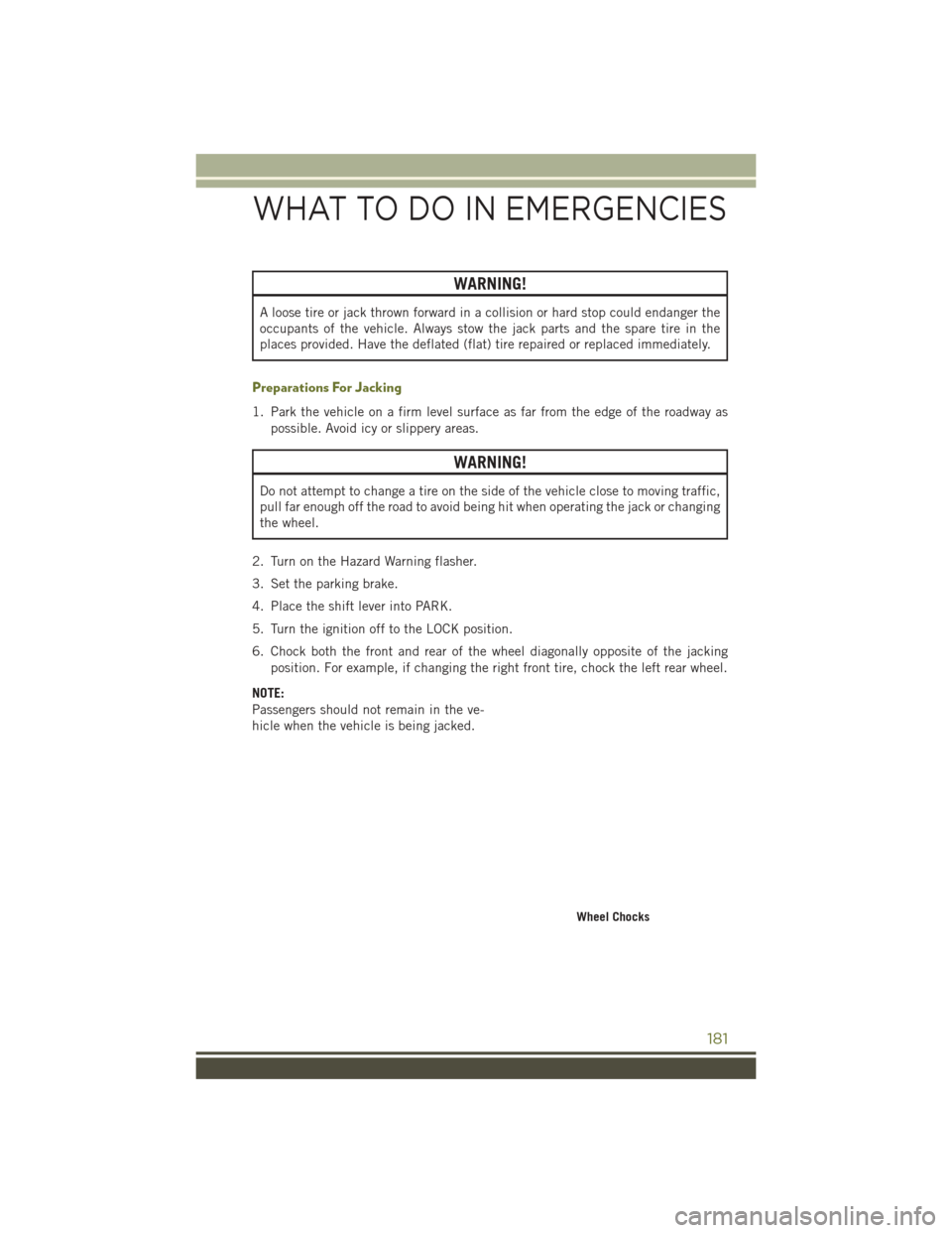
6. Chock both the front and rear of the wheel diagonally opposite of the jacking position. For example, if changing the right front tire, chock the left rear wheel.
NOTE:
Passengers should not remain in the ve-
hicle when the vehicle is being jacked.
Wheel Chocks
WHAT TO DO IN EMERGENCIES
181
Page 184 of 236
Jacking Instructions
WARNING!
Carefully follow these tire changing warnings to help prevent personal injury or
damage to your vehicle:
• Always park on a firm, level surface as far from the edge of the roadway aspossible before raising the vehicle.
• Turn on the Hazard Warning flasher.
• Chock the wheel diagonally opposite the wheel to be raised.
• Set the parking brake firmly and set the transmission in PARK.
• Never start or run the engine with the vehicle on a jack.
• Do not let anyone sit in the vehicle when it is on a jack.
• Do not get under the vehicle when it is on a jack. If you need to get under a
raised vehicle, take it to a service center where it can be raised on a lift.
• Only use the jack in the positions indicated and for lifting this vehicle during
a tire change.
• If working on or near a roadway, be extremely careful of motor traffic.
• To assure that spare tires, flat or inflated, are securely stowed, spares must be
stowed with the valve stem facing the ground.
CAUTION!
Do not attempt to raise the vehicle by jacking on locations other than those
indicated in the Jacking Instructions for this vehicle.
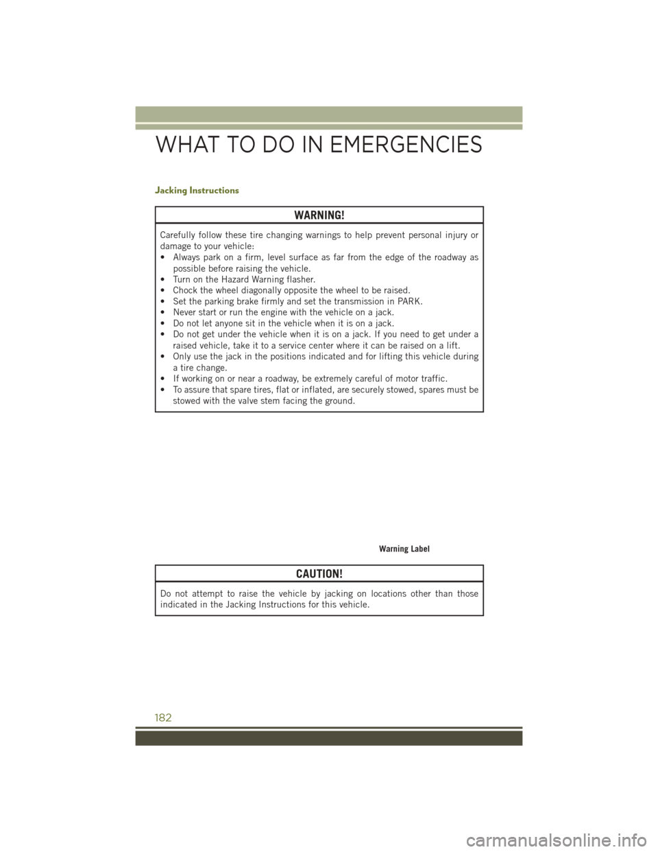
Warning Label
WHAT TO DO IN EMERGENCIES
182
Page 187 of 236
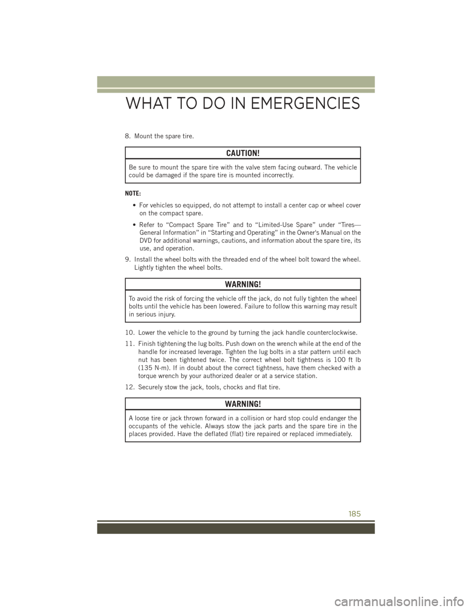
8. Mount the spare tire.
CAUTION!
Be sure to mount the spare tire with the valve stem facing outward. The vehicle
could be damaged if the spare tire is mounted incorrectly.
NOTE: • For vehicles so equipped, do not attempt to install a center cap or wheel coveron the compact spare.
• Refer to “Compact Spare Tire” and to “Limited-Use Spare” under “Tires— General Information” in “Starting and Operating” in the Owner's Manual on the
DVD for additional warnings, cautions, and information about the spare tire, its
use, and operation.
9. Install the wheel bolts with the threaded end of the wheel bolt toward the wheel. Lightly tighten the wheel bolts.
WARNING!
To avoid the risk of forcing the vehicle off the jack, do not fully tighten the wheel
bolts until the vehicle has been lowered. Failure to follow this warning may result
in serious injury.
10. Lower the vehicle to the ground by turning the jack handle counterclockwise.
11. Finish tightening the lug bolts. Push down on the wrench while at the end of the handle for increased leverage. Tighten the lug bolts in a star pattern until each
nut has been tightened twice. The correct wheel bolt tightness is 100 ft lb
(135 N·m). If in doubt about the correct tightness, have them checked with a
torque wrench by your authorized dealer or at a service station.
12. Securely stow the jack, tools, chocks and flat tire.
WARNING!
A loose tire or jack thrown forward in a collision or hard stop could endanger the
occupants of the vehicle. Always stow the jack parts and the spare tire in the
places provided. Have the deflated (flat) tire repaired or replaced immediately.
WHAT TO DO IN EMERGENCIES
185
Page 188 of 236
Road Tire Installation
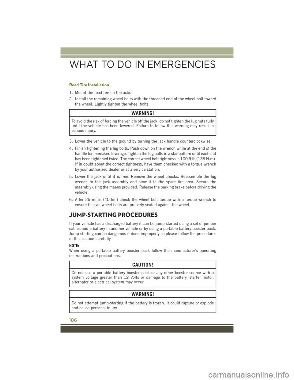
1. Mount the road tire on the axle.
2. Install the remaining wheel bolts with the threaded end of the wheel bolt towardthe wheel. Lightly tighten the wheel bolts.
WARNING!
To avoid the risk of forcing the vehicle off the jack, do not tighten the lug nuts fully
until the vehicle has been lowered. Failure to follow this warning may result in
serious injury.
3. Lower the vehicle to the ground by turning the jack handle counterclockwise.
4. Finish tightening the lug bolts. Push down on the wrench while at the end of the handle for increased leverage. Tighten the lug bolts in a star pattern until each nut
has been tightened twice. The correct wheel bolt tightness is 100 ft lb (135 N·m).
If in doubt about the correct tightness, have them checked with a torque wrench
by your authorized dealer or at a service station.
5. Lower the jack until it is free. Remove the wheel chocks. Reassemble the lug wrench to the jack assembly and stow it in the spare tire area. Secure the
assembly using the means provided. Release the parking brake before driving the
vehicle.
6. After 25 miles (40 km) check the wheel bolt torque with a torque wrench to ensure that all wheel bolts are properly seated against the wheel.
JUMP-STARTING PROCEDURES
If your vehicle has a discharged battery it can be jump-started using a set of jumper
cables and a battery in another vehicle or by using a portable battery booster pack.
Jump-starting can be dangerous if done improperly so please follow the procedures
in this section carefully.
NOTE:
When using a portable battery booster pack follow the manufacturer’s operating
instructions and precautions.
CAUTION!
Do not use a portable battery booster pack or any other booster source with a
system voltage greater than 12 Volts or damage to the battery, starter motor,
alternator or electrical system may occur.
WARNING!
Do not attempt jump-starting if the battery is frozen. It could rupture or explode
and cause personal injury.
WHAT TO DO IN EMERGENCIES
186
Page 192 of 236
RECOVERY STRAP — IF EQUIPPED
Your vehicle may be included with a recovery strap. Recovery straps do not act like
traditional tow straps, chains, or winch cables.
WARNING!
Recovery straps should only be used in emergencies to rescue stranded vehicles.
Only use Recovery straps on vehicles that fit within the recommended GVW of your
recovery strap. Only attach recovery straps to OE recommended anchor points or
emergency towing anchor points. Never attach to tow ball or vehicle tie down
point, these are not designed for this purpose. Never attach to vehicle steering,
drive train, or any other suspension components. NEVER pull a strap over sharp
edges or abrasive surfaces that can damage the recovery strap. NEVER use a
damaged strap, it has reduced strength. DO NOT attempt to repair straps. ONLY
persons involved in the recovery should be in either vehicle. No passengers.
Anyone inside the vehicles can be struck by strap recoil, causing serious injury.
MOVE bystanders at least 40 feet from the recovery area when using the recovery
strap.
Using Recovery Strap
1. Review all warnings and instructions first.
2. Position the recovery vehicle.
3. Connect the recovery strap.
4. Add a recovery damper or blanket.
5. Clear the danger zone.
6. Safely and slowly start pulling.
7. Disconnect the recovery strap after both vehicle are secure and parked.
SHIFT LEVER OVERRIDE
If a malfunction occurs and the shift lever cannot be moved out of the PARK position,
you can use the following procedure to temporarily move the shift lever:
1. Turn the engine OFF.
2. Apply the parking brake.
3. Using a screwdriver or similar tool, carefully separate the shifter bezel and boot assembly from the center console.
4. Press and maintain firm pressure on the brake pedal.
WHAT TO DO IN EMERGENCIES
190
Page 193 of 236
5. Insert a small screwdriver or similar tool down into the shift lever override accesshole (at the right front corner of the shift lever assembly), and push and hold the
override release lever down.
6. Move the shift lever to the NEUTRAL position.
7. The vehicle may then be started in NEUTRAL.
8. Reinstall the shift lever boot.
TOWING A DISABLED VEHICLE
4X4 MODELS
Towing
Condition Wheels OFF
the Ground
FWD MOD- ELS1–SPEED
POWER TRANSFER UNIT 2–SPEED
POWER TRANSFER UNIT
Flat Tow NONENOT
ALLOWED NOT ALLOWED See instructions under
“Recreational Towing” in “Utility”
• Transmission in
PARK
• Power Transfer
Unit in NEUTRAL
• Tow in forward
direction
Wheel Lift or
Dolly Tow Rear
NOT
ALLOWED NOT ALLOWED NOT ALLOWED
Front OK NOT ALLOWED NOT ALLOWED
Flatbed ALLBEST
METHOD OK
BEST METHOD
NOTE:
You must ensure that the Auto Park Brake feature is disabled before towing this
vehicle, to avoid inadvertent Electric Park Brake engagement. The Auto Park Brake
feature is enabled or disabled via the customer programmable features in the
Uconnect Settings.
WHAT TO DO IN EMERGENCIES
191
Page 195 of 236
TO OPEN AND CLOSE THE HOOD
Two latches must be released to open the hood.
1. Pull the hood release lever located under the drivers side of the instrument panel.
2. Move to the outside of the vehicle and pull the safety latch release lever forward(toward you). The safety latch release lever is located behind the front edge of the
hood, slightly off-center to the right.
CAUTION!
To prevent possible damage, do not slam the hood to close it. Lower the hood until
it is open approximately 6 inches (15 cm), and then drop it. This should secure
both latches. Never drive your vehicle unless the hood is fully closed, with both
latches engaged.
WARNING!
Be sure the hood is fully latched before driving your vehicle. If the hood is not fully
latched, it could open when the vehicle is in motion and block your vision. Failure
to follow this warning could result in serious injury or death.
MAINTAINING YOUR VEHICLE
193
Page 202 of 236
FLEXIBLE FUEL (2.4L ENGINE ONLY) — IF EQUIPPED
E-85 General Information
The information in this section is unique for Flexible Fuel vehicles only. These
vehicles can be identified by a unique fuel filler door label that statesEthanol (E-85)
or Unleaded Gasoline Only and a yellow fuel cap. Refer to the Owner’s Manual on the
DVD for further information.
CAUTION!
Only vehicles with the E-85 fuel filler door label or a yellow gas cap can operate on
E-85.
MAINTENANCE PROCEDURES
For information on the maintenance procedures for your vehicle, please refer to
“Maintenance Procedures” in “Maintaining Your Vehicle” in your Owner’s Manual or
applicable supplement on the DVD for further details.
MAINTENANCE SCHEDULE
Your vehicle is equipped with an automatic oil change indicator system. The oil
change indicator system will remind you that it is time to take your vehicle in for
scheduled maintenance.
Based on engine operation conditions, the oil change indicator message will
illuminate. This means that service is required for your vehicle. Operating conditions
such as frequent short-trips, trailer tow, extremely hot or cold ambient temperatures
will influence when the “Oil Change Required” message is displayed. Severe
Operating Conditions can cause the change oil message to illuminate as early as
3,500 miles (5,600 km) since last reset. Have your vehicle serviced as soon as
possible, within the next 500 miles (805 km).
Your authorized dealer will reset the oil change indicator message after completing the
scheduled oil change. If a scheduled oil change is performed by someone other than
your authorized dealer, the message can be reset by referring to the steps described
under “Instrument Cluster Warning Lights” in “What To Do In Emergencies” in this
guide or “Electronic Vehicle Information Center (EVIC)” or “Driver Information Display
(DID)” in “Understanding Your Instrument Panel” in your Owners Manual on the DVD for
further information.
MAINTAINING YOUR VEHICLE
200
Page 207 of 236
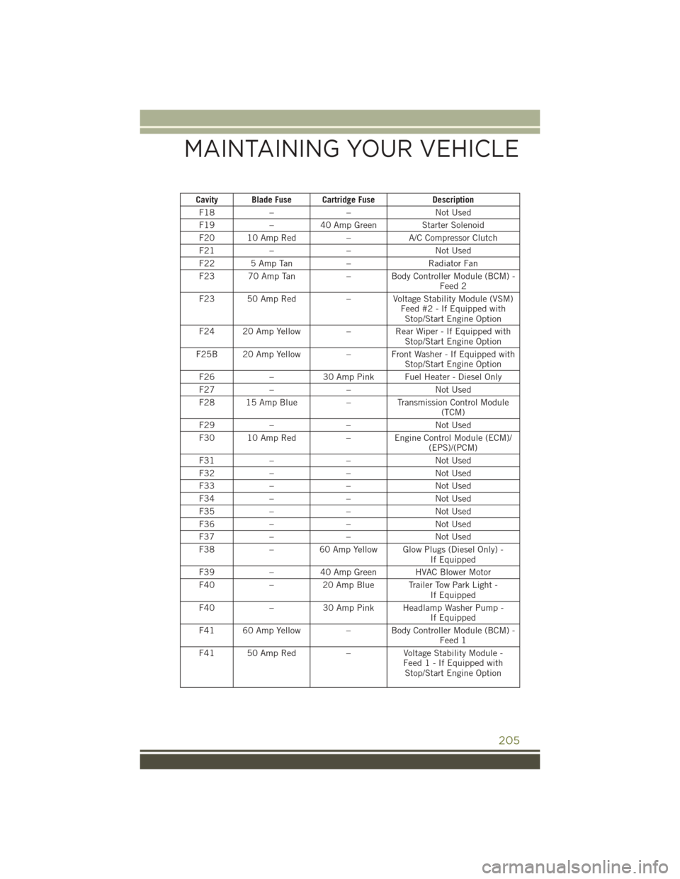
Cavity Blade Fuse Cartridge FuseDescription
F18 – – Not Used
F19 –40 Amp Green Starter Solenoid
F20 10 Amp Red –A/C Compressor Clutch
F21 – – Not Used
F22 5 Amp Tan –Radiator Fan
F23 70 Amp Tan – Body Controller Module (BCM) -
Feed 2
F23 50 Amp Red – Voltage Stability Module (VSM)
Feed #2 - If Equipped withStop/Start Engine Option
F24 20 Amp Yellow –Rear Wiper - If Equipped with
Stop/Start Engine Option
F25B 20 Amp Yellow – Front Washer - If Equipped with
Stop/Start Engine Option
F26 –30 Amp Pink Fuel Heater - Diesel Only
F27 – – Not Used
F28 15 Amp Blue –Transmission Control Module
(TCM)
F29 – – Not Used
F30 10 Amp Red – Engine Control Module (ECM)/
(EPS)/(PCM)
F31 – – Not Used
F32 – – Not Used
F33 – – Not Used
F34 – – Not Used
F35 – – Not Used
F36 – – Not Used
F37 – – Not Used
F38 –60 Amp Yellow Glow Plugs (Diesel Only) -
If Equipped
F39 –40 Amp Green HVAC Blower Motor
F40 –20 Amp Blue Trailer Tow Park Light -
If Equipped
F40 –30 Amp Pink Headlamp Washer Pump -
If Equipped
F41 60 Amp Yellow – Body Controller Module (BCM) -
Feed 1
F41 50 Amp Red –Voltage Stability Module -
Feed 1 - If Equipped with Stop/Start Engine Option
MAINTAINING YOUR VEHICLE
205
Page 208 of 236
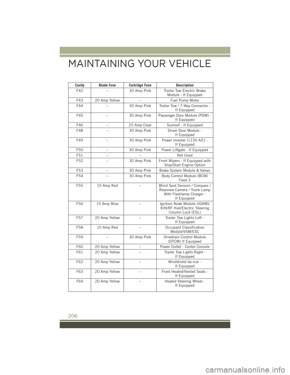
Cavity Blade Fuse Cartridge FuseDescription
F42 –30 Amp Pink Trailer Tow Electric Brake
Module - If Equipped
F43 20 Amp Yellow –Fuel Pump Motor
F44 –30 Amp Pink Trailer Tow / 7-Way Connector -
If Equipped
F45 –30 Amp Pink Passenger Door Module (PDM) -
If Equipped
F46 –25 Amp Clear Sunroof - If Equipped
F48 –30 Amp Pink Driver Door Module -
If Equipped
F49 –30 Amp Pink Power Inverter (115V A/C) -
If Equipped
F50 –30 Amp Pink Power Liftgate - If Equipped
F51 – – Not Used
F52 –30 Amp Pink Front Wipers - If Equipped with
Stop/Start Engine Option
F53 –30 Amp Pink Brake System Module & Valves
F54 –30 Amp Pink Body Control Module (BCM)
Feed 3
F55 10 Amp Red – Blind Spot Sensors / Compass /
Rearview Camera / Trunk LampWith Flashlamp Charger - If Equipped
F56 15 Amp Blue – Ignition Node Module (IGNM)/
KIN/RF Hub/Electric SteeringColumn Lock (ESL)
F57 20 Amp Yellow –Trailer Tow Lights Left -
If Equipped
F58 10 Amp Red –Occupant Classification
Module/VSM/ESC
F59 –30 Amp Pink Drivetrain Control Module
(DTCM) If Equipped
F60 20 Amp Yellow –Power Outlet - Center Console
F61 20 Amp Yellow –Trailer Tow Lights Right -
If Equipped
F62 20 Amp Yellow –Windshield de-icer -
If Equipped
F63 20 Amp Yellow –Front Heated/Vented Seats -
If Equipped
F64 20 Amp Yellow –Heated Steering Wheel -
If Equipped
MAINTAINING YOUR VEHICLE
206