fuse JEEP CHEROKEE 2017 KL / 5.G Owner's Manual
[x] Cancel search | Manufacturer: JEEP, Model Year: 2017, Model line: CHEROKEE, Model: JEEP CHEROKEE 2017 KL / 5.GPages: 615, PDF Size: 5.72 MB
Page 409 of 615
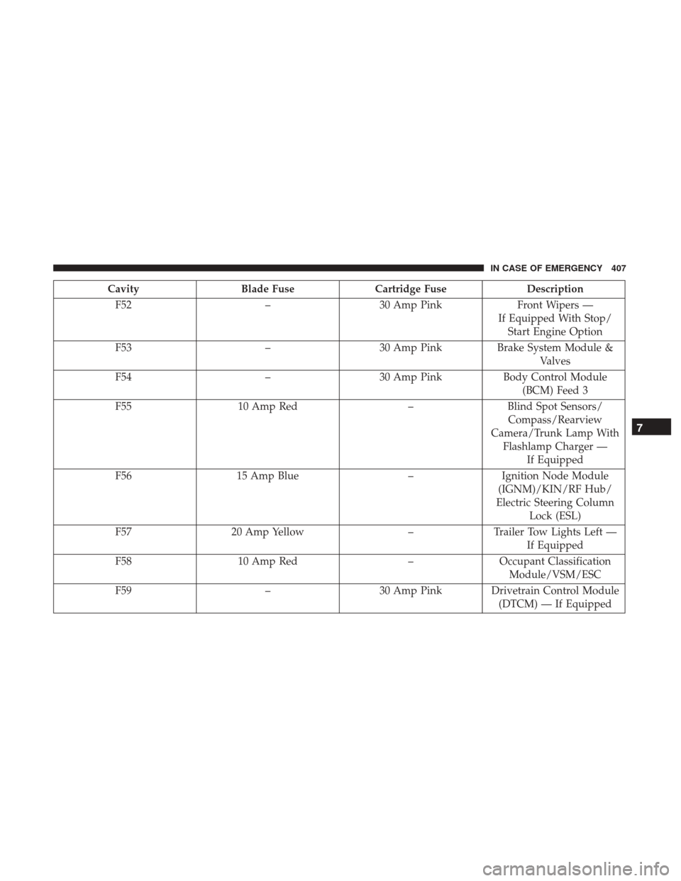
CavityBlade Fuse Cartridge Fuse Description
F52 –30 Amp Pink Front Wipers —
If Equipped With Stop/ Start Engine Option
F53 –30 Amp Pink Brake System Module &
Valves
F54 –30 Amp Pink Body Control Module
(BCM) Feed 3
F55 10 Amp Red –Blind Spot Sensors/
Compass/Rearview
Camera/Trunk Lamp With Flashlamp Charger — If Equipped
F56 15 Amp Blue –Ignition Node Module
(IGNM)/KIN/RF Hub/
Electric Steering Column Lock (ESL)
F57 20 Amp Yellow –Trailer Tow Lights Left —
If Equipped
F58 10 Amp Red –Occupant Classification
Module/VSM/ESC
F59 –30 Amp Pink Drivetrain Control Module
(DTCM) — If Equipped
7
IN CASE OF EMERGENCY 407
Page 410 of 615
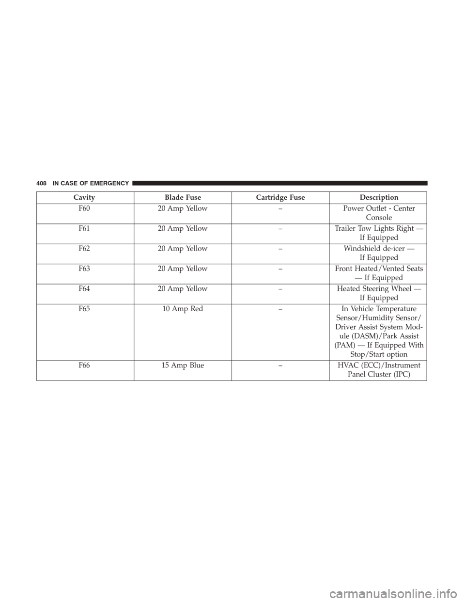
CavityBlade Fuse Cartridge Fuse Description
F60 20 Amp Yellow –Power Outlet - Center
Console
F61 20 Amp Yellow –Trailer Tow Lights Right —
If Equipped
F62 20 Amp Yellow –Windshield de-icer —
If Equipped
F63 20 Amp Yellow –Front Heated/Vented Seats
— If Equipped
F64 20 Amp Yellow –Heated Steering Wheel —
If Equipped
F65 10 Amp Red –In Vehicle Temperature
Sensor/Humidity Sensor/
Driver Assist System Mod- ule (DASM)/Park Assist
(PAM) — If Equipped With Stop/Start option
F66 15 Amp Blue –HVAC (ECC)/Instrument
Panel Cluster (IPC)
408 IN CASE OF EMERGENCY
Page 411 of 615
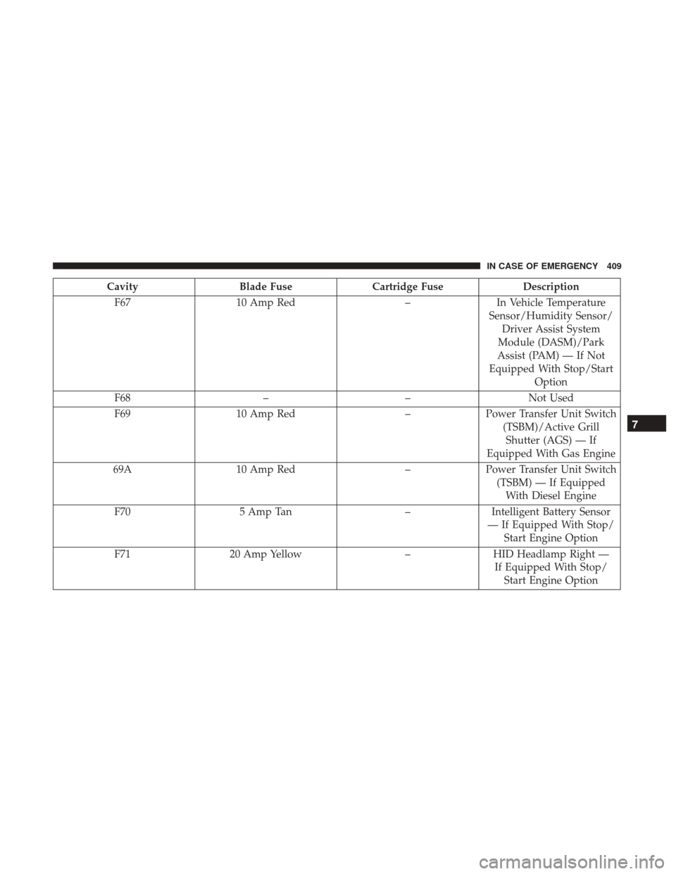
CavityBlade Fuse Cartridge Fuse Description
F67 10 Amp Red –In Vehicle Temperature
Sensor/Humidity Sensor/ Driver Assist System
Module (DASM)/Park
Assist (PAM) — If Not
Equipped With Stop/Start Option
F68 ––Not Used
F69 10 Amp Red –Power Transfer Unit Switch
(TSBM)/Active GrillShutter (AGS) — If
Equipped With Gas Engine
69A 10 Amp Red –Power Transfer Unit Switch
(TSBM) — If EquippedWith Diesel Engine
F70 5 Amp Tan –Intelligent Battery Sensor
— If Equipped With Stop/ Start Engine Option
F71 20 Amp Yellow –HID Headlamp Right —
If Equipped With Stop/ Start Engine Option
7
IN CASE OF EMERGENCY 409
Page 412 of 615
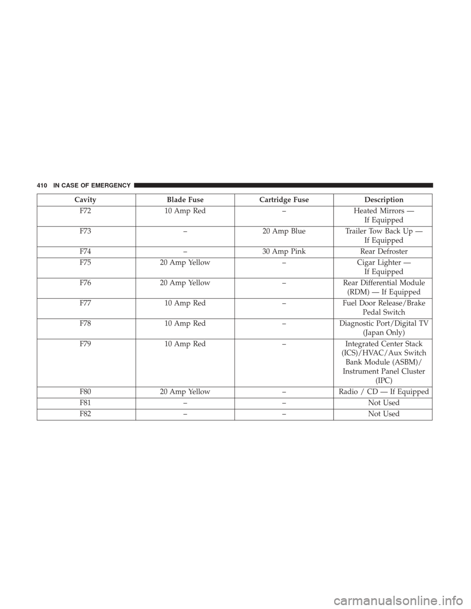
CavityBlade Fuse Cartridge Fuse Description
F72 10 Amp Red –Heated Mirrors —
If Equipped
F73 –20 Amp Blue Trailer Tow Back Up —
If Equipped
F74 –30 Amp Pink Rear Defroster
F75 20 Amp Yellow –Cigar Lighter —
If Equipped
F76 20 Amp Yellow –Rear Differential Module
(RDM) — If Equipped
F77 10 Amp Red –Fuel Door Release/Brake
Pedal Switch
F78 10 Amp Red –Diagnostic Port/Digital TV
(Japan Only)
F79 10 Amp Red –Integrated Center Stack
(ICS)/HVAC/Aux Switch Bank Module (ASBM)/
Instrument Panel Cluster (IPC)
F80 20 Amp Yellow –Radio / CD — If Equipped
F81 ––Not Used
F82 ––Not Used
410 IN CASE OF EMERGENCY
Page 413 of 615
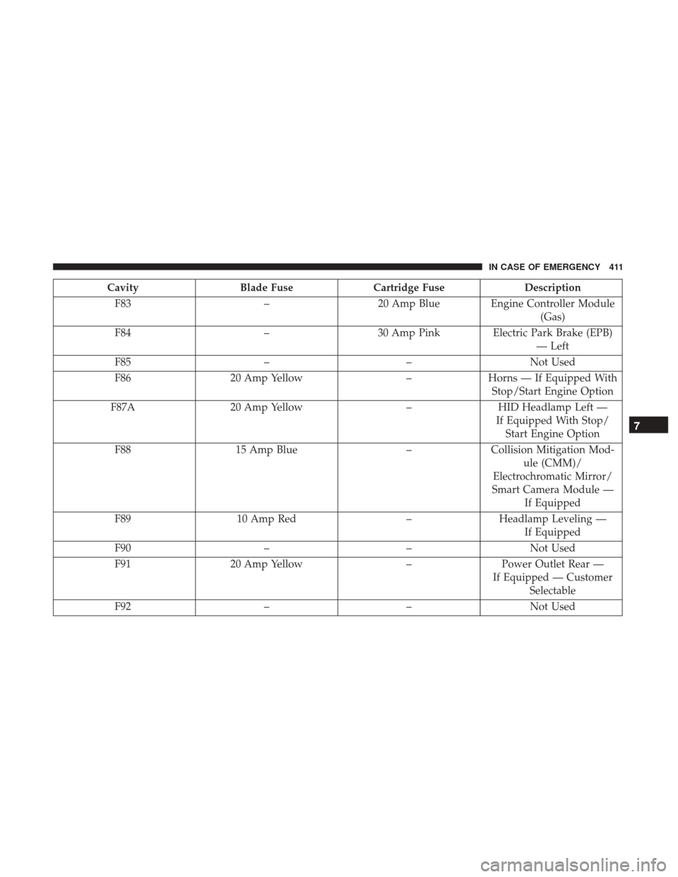
CavityBlade Fuse Cartridge Fuse Description
F83 –20 Amp Blue Engine Controller Module
(Gas)
F84 –30 Amp Pink Electric Park Brake (EPB)
— Left
F85 ––Not Used
F86 20 Amp Yellow –Horns — If Equipped With
Stop/Start Engine Option
F87A 20 Amp Yellow –HID Headlamp Left —
If Equipped With Stop/ Start Engine Option
F88 15 Amp Blue –Collision Mitigation Mod-
ule (CMM)/
Electrochromatic Mirror/
Smart Camera Module — If Equipped
F89 10 Amp Red –Headlamp Leveling —
If Equipped
F90 ––Not Used
F91 20 Amp Yellow –Power Outlet Rear —
If Equipped — Customer Selectable
F92 ––Not Used
7
IN CASE OF EMERGENCY 411
Page 414 of 615
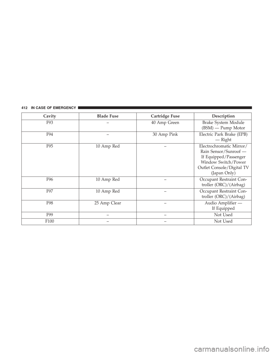
CavityBlade Fuse Cartridge Fuse Description
F93 –40 Amp Green Brake System Module
(BSM) — Pump Motor
F94 –30 Amp Pink Electric Park Brake (EPB)
— Right
F95 10 Amp Red –Electrochromatic Mirror/
Rain Sensor/Sunroof —If Equipped/Passenger
Window Switch/Power
Outlet Console/Digital TV (Japan Only)
F96 10 Amp Red –Occupant Restraint Con-
troller (ORC)/(Airbag)
F97 10 Amp Red –Occupant Restraint Con-
troller (ORC)/(Airbag)
F98 25 Amp Clear –Audio Amplifier —
If Equipped
F99 ––Not Used
F100 ––Not Used
412 IN CASE OF EMERGENCY
Page 415 of 615
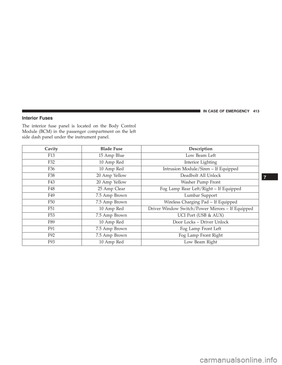
Interior Fuses
The interior fuse panel is located on the Body Control
Module (BCM) in the passenger compartment on the left
side dash panel under the instrument panel.
CavityBlade Fuse Description
F13 15 Amp Blue Low Beam Left
F32 10 Amp Red Interior Lighting
F36 10 Amp Red Intrusion Module/Siren – If Equipped
F38 20 Amp Yellow Deadbolt All Unlock
F43 20 Amp Yellow Washer Pump Front
F48 25 Amp Clear Fog Lamp Rear Left/Right – If Equipped
F49 7.5 Amp Brown Lumbar Support
F50 7.5 Amp Brown Wireless Charging Pad – If Equipped
F51 10 Amp RedDriver Window Switch/Power Mirrors – If Equipped
F53 7.5 Amp Brown UCI Port (USB & AUX)
F89 10 Amp Red Door Locks – Driver Unlock
F91 7.5 Amp Brown Fog Lamp Front Left
F92 7.5 Amp Brown Fog Lamp Front Right
F93 10 Amp Red Low Beam Right
7
IN CASE OF EMERGENCY 413
Page 453 of 615
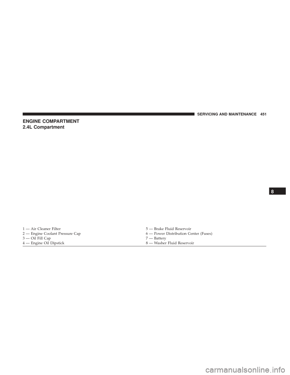
ENGINE COMPARTMENT
2.4L Compartment
1 — Air Cleaner Filter5 — Brake Fluid Reservoir
2 — Engine Coolant Pressure Cap 6 — Power Distribution Center (Fuses)
3 — Oil Fill Cap 7 — Battery
4 — Engine Oil Dipstick 8 — Washer Fluid Reservoir
8
SERVICING AND MAINTENANCE 451
Page 454 of 615
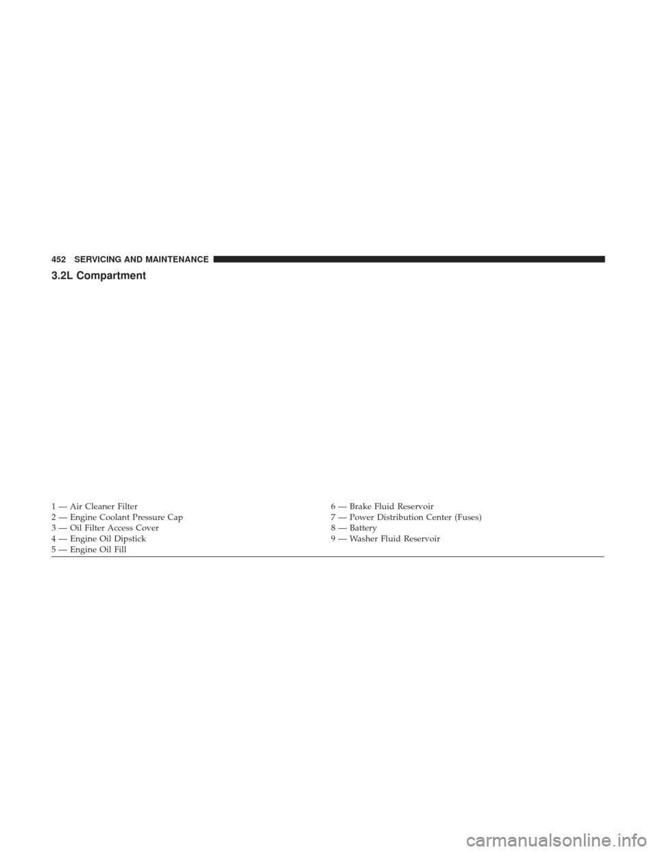
3.2L Compartment
1 — Air Cleaner Filter6 — Brake Fluid Reservoir
2 — Engine Coolant Pressure Cap 7 — Power Distribution Center (Fuses)
3 — Oil Filter Access Cover 8 — Battery
4 — Engine Oil Dipstick 9 — Washer Fluid Reservoir
5 — Engine Oil Fill 452 SERVICING AND MAINTENANCE
Page 614 of 615

INSTALLATION OF RADIO TRANSMITTING
EQUIPMENT
Special design considerations are incorporated into this
vehicle’s electronic system to provide immunity to radio
frequency signals. Mobile two-way radios and telephone
equipment must be installed properly by trained person-
nel. The following must be observed during installation.
The positive power connection should be made directly
to the battery and fused as close to the battery as possible.
The negative power connection should be made to body
sheet metal adjacent to the negative battery connection.
This connection should not be fused.
Antennas for two-way radios should be mounted on the
roof or the rear area of the vehicle. Care should be used
in mounting antennas with magnet bases. Magnets may
affect the accuracy or operation of the compass on
vehicles so equipped.The antenna cable should be as short as practical and
routed away from the vehicle wiring when possible. Use
only fully shielded coaxial cable.
Carefully match the antenna and cable to the radio to
ensure a low Standing Wave Ratio (SWR).
Mobile radio equipment with output power greater than
normal may require special precautions.
All installations should be checked for possible interfer-
ence between the communications equipment and the
vehicle’s electronic systems.