tow JEEP CHEROKEE 2017 KL / 5.G User Guide
[x] Cancel search | Manufacturer: JEEP, Model Year: 2017, Model line: CHEROKEE, Model: JEEP CHEROKEE 2017 KL / 5.GPages: 615, PDF Size: 5.72 MB
Page 57 of 615
Reactive Head Restraints — Front Seats
The front driver and passenger seats are equipped with
Reactive Head Restraints (RHR). In the event of a rear
impact the RHRs will automatically extend forward mini-
mizing the gap between the back of the occupant’s head
and the RHR.
The RHRs will automatically return to their normal posi-
tion following a rear impact. If the RHRs do not return to
their normal position see your authorized dealer immedi-
ately.
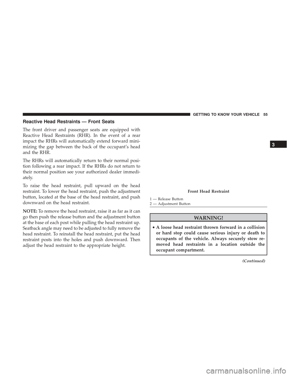
To raise the head restraint, pull upward on the head
restraint. To lower the head restraint, push the adjustment
button, located at the base of the head restraint, and push
downward on the head restraint.
NOTE:To remove the head restraint, raise it as far as it can
go then push the release button and the adjustment button
at the base of each post while pulling the head restraint up.
Seatback angle may need to be adjusted to fully remove the
head restraint. To reinstall the head restraint, put the head
restraint posts into the holes and push downward. Then
adjust the head restraint to the appropriate height.
WARNING!
• A loose head restraint thrown forward in a collision
or hard stop could cause serious injury or death to
occupants of the vehicle. Always securely stow re-
moved head restraints in a location outside the
occupant compartment.
(Continued)
Front Head Restraint
1 — Release Button
2 — Adjustment Button
3
GETTING TO KNOW YOUR VEHICLE 55
Page 60 of 615
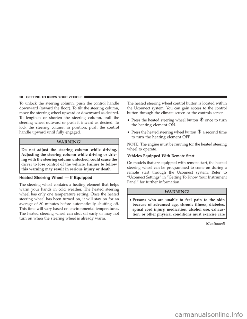
To unlock the steering column, push the control handle
downward (toward the floor). To tilt the steering column,
move the steering wheel upward or downward as desired.
To lengthen or shorten the steering column, pull the
steering wheel outward or push it inward as desired. To
lock the steering column in position, push the control
handle upward until fully engaged.
WARNING!
Do not adjust the steering column while driving.
Adjusting the steering column while driving or driv-
ing with the steering column unlocked, could cause the
driver to lose control of the vehicle. Failure to follow
this warning may result in serious injury or death.
Heated Steering Wheel — If Equipped
The steering wheel contains a heating element that helps
warm your hands in cold weather. The heated steering
wheel has only one temperature setting. Once the heated
steering wheel has been turned on, it will stay on for an
average of 80 minutes before automatically shutting off.
This time will vary based on environmental temperatures.
The heated steering wheel can shut off early or may not
turn on when the steering wheel is already warm.The heated steering wheel control button is located within
the Uconnect system. You can gain access to the control
button through the climate screen or the controls screen.
•
Press the heated steering wheel button
once to turn
the heating element ON.
• Press the heated steering wheel buttona second time
to turn the heating element OFF.
NOTE: The engine must be running for the heated steering
wheel to operate.
Vehicles Equipped With Remote Start
On models that are equipped with remote start, the heated
steering wheel can be programmed to come on during a
remote start through the Uconnect system. Refer to
“Uconnect Settings” in “Getting To Know Your Instrument
Panel” for further information.
WARNING!
• Persons who are unable to feel pain to the skin
because of advanced age, chronic illness, diabetes,
spinal cord injury, medication, alcohol use, exhaus-
tion, or other physical conditions must exercise care
(Continued)
58 GETTING TO KNOW YOUR VEHICLE
Page 61 of 615
WARNING!(Continued)
when using the steering wheel heater. It may cause
burns even at low temperatures, especially if used
for long periods.
• Do not place anything on the steering wheel that
insulates against heat, such as a blanket or steering
wheel covers of any type and material. This may
cause the steering wheel heater to overheat.
MIRRORS
Inside Day/Night Mirror — If Equipped
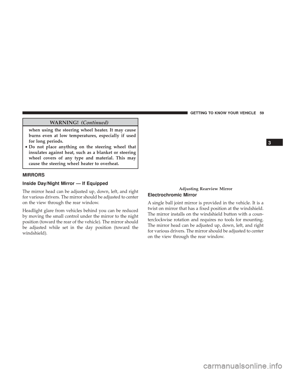
The mirror head can be adjusted up, down, left, and right
for various drivers. The mirror should be adjusted to center
on the view through the rear window.
Headlight glare from vehicles behind you can be reduced
by moving the small control under the mirror to the night
position (toward the rear of the vehicle). The mirror should
be adjusted while set in the day position (toward the
windshield).Electrochromic Mirror
A single ball joint mirror is provided in the vehicle. It is a
twist on mirror that has a fixed position at the windshield.
The mirror installs on the windshield button with a coun-
terclockwise rotation and requires no tools for mounting.
The mirror head can be adjusted up, down, left, and right
for various drivers. The mirror should be adjusted to center
on the view through the rear window.
Adjusting Rearview Mirror
3
GETTING TO KNOW YOUR VEHICLE 59
Page 64 of 615
Resetting The Power Folding Outside Mirrors
You may need to reset the power folding mirrors if the
following occurs:
•The mirrors are accidentally blocked while folding.
• The mirrors are accidentally manually folded/unfolded.
• The mirrors come out of the unfolded position.
• The mirrors shake and vibrate at normal driving speeds.
To reset the power folding mirrors: Fold and unfold them
by pushing the button. (this may require multiple button
pushes). This resets them to their normal position.
Heated Mirrors — If Equipped
These mirrors are heated to melt frost or ice. This
feature will be activated whenever you turn on the
rear window defroster (if equipped). Refer to “Rear Win-
dow Features” in “Getting To Know Your Vehicle” for
further information.
Illuminated Vanity Mirrors — If Equipped
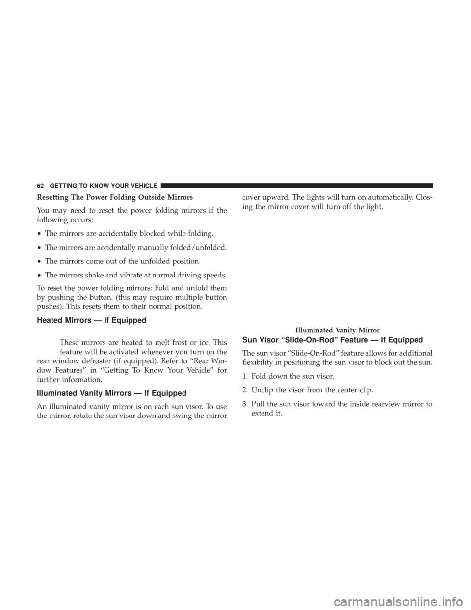
An illuminated vanity mirror is on each sun visor. To use
the mirror, rotate the sun visor down and swing the mirror cover upward. The lights will turn on automatically. Clos-
ing the mirror cover will turn off the light.
Sun Visor “Slide-On-Rod” Feature — If Equipped
The sun visor “Slide-On-Rod” feature allows for additional
flexibility in positioning the sun visor to block out the sun.
1. Fold down the sun visor.
2. Unclip the visor from the center clip.
3. Pull the sun visor toward the inside rearview mirror to
extend it.
Illuminated Vanity Mirror
62 GETTING TO KNOW YOUR VEHICLE
Page 68 of 615
Turn Signals
Move the multifunction lever up or down and the arrows
on each side of the instrument cluster display will flash to
show proper operation of the front and rear turn signal
lights.
NOTE:
•If either light remains on and does not flash, or there is
a very fast flash rate, check for a defective outside light
bulb. If an indicator fails to light when the lever is
moved, it would suggest that the indicator bulb is
defective.
• A “Turn Signal On” message will appear in the instru-
ment cluster display and a continuous chime will sound
if the vehicle is driven more than 1 mile (1.6 km) with
either turn signal on.
• When the Daytime Running Lights are on and a turn
signal is activated, the Daytime Running Lamp will turn
off on the side of the vehicle in which the turn signal is
flashing. The Daytime Running Lamp will turn back on
when the turn signal is turned off.
Lane Change Assist — If Equipped
Tap the lever up or down once, without moving beyond
the detent, and the turn signal (right or left) will flash three
times then automatically turn off.
High/Low Beam Switch
Push the multifunction lever away from you to switch the
headlights to high beam. Pull the multifunction lever
toward you to switch the headlights back to low beam.
Flash-To-Pass
You can signal another vehicle with your headlights by
lightly pulling the multifunction lever toward you. This
will cause the headlights to turn on at high beam and
remain on until the lever is released.
Automatic High Beam Headlamp Control —
If Equipped
The Automatic High Beam Headlamp Control system
provides increased forward lighting at night by automat-
ing high beam control through the use of a digital camera
mounted on the inside rearview mirror. This camera de-
tects vehicle specific light and automatically switches from
high beams to low beams until the approaching vehicle is
out of view.
66 GETTING TO KNOW YOUR VEHICLE
Page 73 of 615
CAUTION!
Always remove any buildup of snow that prevents the
windshield wiper blades from returning to the “park”
position. If the windshield wiper switch is turned off,
and the blades cannot return to the “park” position,
damage to the wiper motor may occur.
Windshield Washer Operation
To use the washer, pull the lever rearward toward you and
hold while spray is desired. If the lever is pulled while in
the intermittent setting, the wipers will turn on and operate
for several wipe cycles after the lever is released, and then
resume the intermittent interval previously selected.
If the lever is pulled while the wipers are in the off position,
the wipers will operate for several wipe cycles, then turn off.
WARNING!
Sudden loss of visibility through the windshield could
lead to a collision. You might not see other vehicles or
other obstacles. To avoid sudden icing of the wind-
shield during freezing weather, warm the windshield
with the defroster before and during windshield
washer use.
Windshield Washer Operation
3
GETTING TO KNOW YOUR VEHICLE 71
Page 89 of 615
IconDescription
AUTO Button — If Equipped
Automatically controls the interior cabin temperature by adjusting airflow distribution and
amount. Performing this function will cause the system to switch between manual mode and
automatic modes. Refer to “Automatic Operation” for more information.
Front Defrost Button
Press and release to change the current airflow setting to Defrost mode. The indicator on the
touchscreen illuminates when this feature is on. Air comes from the windshield and side win-
dow demist outlets. When the defrost button is selected, the blower level will increase. Use De-
frost mode with maximum temperature settings for best windshield and side window defrosting
and defogging. Performing this function will cause the ATC to switch into manual mode. If the
front defrost mode is turned off the climate system will return the previous setting.
Rear Defrost Button
Push and release the Rear Defrost Control button to turn on the rear window defroster and the
heated outside mirrors (if equipped). An indicator will illuminate when the rear window de-
froster is on. The rear window defroster automatically turns off after 10 minutes.
Driver and Passenger Temperature UP and DOWN Buttons — If Equipped
Provides the passenger with independent temperature control. Push the up arrow button on the
faceplate, on the touchscreen, or press and slide the temperature bar towards the red arrow but-
ton on the touchscreen for warmer temperature settings. Push the down arrow button on the
faceplate, on the touchscreen, or press and slide the temperature bar towards the blue arrow
button on the touchscreen for cooler temperature settings. When the SYNC feature is active, the
passenger ’s temperature will move up with the driver ’s temperature, when it is increased.
3
GETTING TO KNOW YOUR VEHICLE 87
Page 104 of 615
HOOD
Opening The Hood
Two latches must be released to open the hood.
1. Pull the hood release lever located under the driver ’sside of the instrument panel. 2. Move to the outside of the vehicle and pull the safety
latch release lever forward (toward you). The safety
latch release lever is located behind the front edge of the
hood, slightly off-center to the right.
Hood Release
Hood Safety Latch Release Lever Location
102 GETTING TO KNOW YOUR VEHICLE
Page 119 of 615
Flip ’n Stow Front Passenger Seat Storage —
If Equipped
Some models may be equipped with storage under the
front passenger seat cushion. Pull upward on the seat
cushion loop to open the storage compartment.NOTE:Make sure that objects inside the bin do not
interfere with the latch before closing the seat. Push the
seat cushion downward after closing it to make sure it
latches to the base.
WARNING!
Be certain that the seat cushion is locked securely into
position before using the seat. Otherwise, the seat will
not provide the proper stability for passengers. An
improperly latched seat cushion could cause serious
injury.
Passenger Seat Cushion Loop
Passenger Seat Cushion Storage Compartment
3
GETTING TO KNOW YOUR VEHICLE 117
Page 126 of 615
The wireless charging pad is equipped with an anti-slip
mat, an adjustable cradle to hold your mobile phone in
place and an LED indicator light.
NOTE:Visit UconnectPhone.com for supported mobile
phones and compatible aftermarket sleeves.
Wireless Charging Pad Operation
To use the wireless charging pad, the coil in your mobile
phone needs to align with the coil in the charging pad,
which is located directly under the Qi logo. Since each
mobile phone’s coil location is different, you may need a
few attempts to locate the correct spot for your mobile
phone:
1. Place your mobile phone on the wireless charging pad, towards the Qi logo, so that the LED turns red. If the
LED does not turn red, pick up the mobile phone and
change the location.
2. Once the LED transitions from red to flashing green, your mobile phone is correctly placed and charging. NOTE:
The mobile phone mustbe aligned around the Qi
logo for the LED to transition from red to flashing green.
3. If the LED does not transition from red to flashing green, and just turns off, pick up your mobile phone and
reposition it on the charging pad.
Qi Logo Phone Alignment
124 GETTING TO KNOW YOUR VEHICLE