turn signal JEEP CHEROKEE 2018 Owner handbook (in English)
[x] Cancel search | Manufacturer: JEEP, Model Year: 2018, Model line: CHEROKEE, Model: JEEP CHEROKEE 2018Pages: 312, PDF Size: 4.91 MB
Page 90 of 312
9. If the air bag system in this vehicle needsto be modified to accommodate a dis-
abled person, refer to the “Customer As-
sistance” section for customer service
contact information.
WARNING!
• NEVER use a rearward facing child re-straint on a seat protected by an ACTIVE
AIRBAG in front of it, DEATH or SERI-
OUS INJURY to the CHILD can occur.
• Only use a rear-facing child restraint in
the rear seat of a vehicle with a rear seat.
• A deploying passenger front air bag can
cause death or serious injury to a child
12 years or younger, including a child in
a rear-facing child restraint.
Seat Belt Systems
Buckle up even though you are an excellent
driver, even on short trips. Someone on the
road may be a poor driver and could cause a
collision that includes you. This can happen
far away from home or on your own street. Research has shown that seat belts save
lives, and they can reduce the seriousness of
injuries in a collision. Some of the worst
injuries happen when people are thrown from
the vehicle. Seat belts reduce the possibility
of ejection and the risk of injury caused by
striking the inside of the vehicle. Everyone in
a motor vehicle should be belted at all times.
Enhanced Seat Belt Use Reminder System
(BeltAlert)
Front And Rear Seat BeltAlert (If Equipped)
Front Seat BeltAlert
BeltAlert is a feature intended to remind
the driver and outboard front seat passenger
to buckle their seat belts. The BeltAlert fea-
ture is active whenever the ignition switch is
in the START or ON/RUN position.
Initial Indication
If the driver is unbuckled when the ignition
switch is first in the START or ON/RUN posi-
tion a chime will signal for a few seconds. If
the driver or outboard front seat passenger is
unbuckled when the ignition switch is first in
the START or ON/RUN position the respec- tive Seat Belt Reminder Light will turn solid
red and remain red until the seat belt is
buckled. The respective Seat Belt Reminder
Light will turn solid green once the seat belt
is buckled. After the driver and outboard
front seat passenger have buckled their seat
belts all Seat Belt Reminder Lights will turn
off. The outboard front passenger seat
BeltAlert is not active when the outboard
front passenger seat is unoccupied.
BeltAlert Warning Sequence
The BeltAlert warning sequence is activated
when the vehicle is moving above a specified
vehicle speed range and the driver or out-
board front seat passenger is unbuckled (the
outboard front passenger seat BeltAlert is not
active when the outboard front passenger
seat is unoccupied). The BeltAlert warning
sequence starts by blinking the respective
Seat Belt Reminder Light and sounding an
intermittent chime. Once the BeltAlert warn-
ing sequence has completed, the Seat Belt
Reminder Light will remain solid red until the
driver and outboard front seat passenger are
buckled. The BeltAlert warning sequence
may repeat based on vehicle speed until the
SAFETY
88
Page 120 of 312
WARNING!
• ONLY use the driver’s side floor mat onthe driver’s side floor area. To check for
interference, with the vehicle properly
parked with the engine off, fully depress
the accelerator, the brake, and the
clutch pedal (if present) to check for
interference. If your floor mat interferes
with the operation of any pedal, or is not
secure to the floor, remove the floor mat
from the vehicle and place the floor mat
in your trunk.
• ONLY use the passenger’s side floor mat
on the passenger’s side floor area.
• ALWAYS make sure objects cannot fall or
slide into the driver’s side floor area
when the vehicle is moving. Objects can
become trapped under accelerator,
brake, or clutch pedals and could cause
a loss of vehicle control.
•
NEVER place any objects under the floor
mat (e.g., towels, keys, etc.). These ob-
jects could change the position of the
floor mat and may cause interference with
the accelerator, brake, or clutch pedals.
WARNING!
•If the vehicle carpet has been removed
and re-installed, always properly attach
carpet to the floor and check the floor mat
fasteners are secure to the vehicle carpet.
Fully depress each pedal to check for
interference with the accelerator, brake,
or clutch pedals then re-install the floor
mats.
• It is recommended to only use mild soap
and water to clean your floor mats. After
cleaning, always check your floor mat
has been properly installed and is se-
cured to your vehicle using the floor mat
fasteners by lightly pulling mat.
Periodic Safety Checks You Should Make
Outside The Vehicle
Tires
Examine tires for excessive tread wear and
uneven wear patterns. Check for stones,
nails, glass, or other objects lodged in the
tread or sidewall. Inspect the tread for cuts
and cracks. Inspect sidewalls for cuts, cracks, and bulges. Check the wheel nuts for
tightness. Check the tires (including spare)
for proper cold inflation pressure.
Lights
Have someone observe the operation of brake
lights and exterior lights while you work the
controls. Check turn signal and high beam
indicator lights on the instrument panel.
Door Latches
Check for proper closing, latching, and locking.
Fluid Leaks
Check area under the vehicle after overnight
parking for fuel, coolant, oil, or other fluid
leaks. Also, if gasoline fumes are detected or
if fuel, or brake fluid leaks are suspected. The
cause should be located and corrected imme-
diately.
SAFETY
118
Page 153 of 312
The ParkSense Active Park Assist system is
intended to assist the driver during parallel
and perpendicular parking maneuvers by
identifying a proper parking space, providing
audible/visual instructions, and controlling
the steering wheel. The ParkSense Active
Park Assist system is defined as “semi-
automatic” since the driver maintains control
of the accelerator, gear selector and brakes.
Depending on the driver’s parking maneuver
selection, the ParkSense Active Park Assist
system is capable of maneuvering a vehicle
into a parallel or a perpendicular parking
space on either side (i.e., driver side or pas-
senger side).
NOTE:
The ParkSense Active Park Assist system
automatically defaults to looking for vehicles
on the right.To search for a parking spot on the
left, use the left turn signal.
Refer to your Owner's Manual for further
information.WARNING!
• Drivers must be careful when backing up even when using ParkSense. Always
check carefully behind your vehicle, look
behind you, and be sure to check for
pedestrians, animals, other vehicles, ob-
structions, and blind spots before back-
ing up. You are responsible for safety
and must continue to pay attention to
your surroundings. Failure to do so can
result in serious injury or death.
• Before using ParkSense, it is strongly
recommended that the ball mount and
hitch ball assembly is disconnected
from the vehicle when the vehicle is not
used for towing. Failure to do so can
result in injury or damage to vehicles or
obstacles because the hitch ball will be
much closer to the obstacle than the rear
fascia when the loudspeaker sounds the
continuous tone. Also, the sensors could
detect the ball mount and hitch ball
assembly, depending on its size and
shape, giving a false indication that an
obstacle is behind the vehicle.
CAUTION!
• ParkSense is only a parking aid and it isunable to recognize every obstacle, in-
cluding small obstacles. Parking curbs
might be temporarily detected or not
detected at all. Obstacles located above
or below the sensors will not be detected
when they are in close proximity.
• The vehicle must be driven slowly when
using ParkSense in order to be able to
stop in time when an obstacle is de-
tected. It is recommended that the
driver looks over his/her shoulder when
using ParkSense.
LANESENSE
LaneSense Operation
The LaneSense system is operational at
speeds above 37 mph (60 km/h) and below
112 mph (180 km/h). The LaneSense system
uses a forward looking camera to detect lane
markings and measure vehicle position
within the lane boundaries.
151
Page 154 of 312
When both lane markings are detected and
the driver unintentionally drifts out of the
lane (no turn signal applied), the LaneSense
system provides a haptic warning in the form
of torque applied to the steering wheel, as
well as a visual warning in the instrument
cluster display, to prompt the driver to remain
within the lane boundaries.
The driver may manually override the haptic
warning by applying torque into the steering
wheel at any time.
When only a single lane marking is detected
and the driver unintentionally drifts across the
lane marking (no turn signal applied), the
LaneSense system provides a visual warning
through the instrument cluster display to
prompt the driver to remain within the lane.
When only a single lane marking is detected, a
haptic (torque) warning will not be provided.
NOTE:
When operating conditions have been met,
the LaneSense system will monitor if thedriver’s hands are on the steering wheel and
provide an audible and visual warning to the
driver when the driver’s hands are not de-
tected on the steering wheel. The system will
cancel if the driver does not return their
hands to the wheel.
Turning LaneSense On Or Off
The default status of LaneSense is “off”.
The LaneSense button is located on the
switch panel below the Uconnect display.
To turn the LaneSense system on, push the
LaneSense button (LED turns off). A “Lane-
Sense On” message is shown in the instru-
ment cluster display.
To turn the LaneSense system off, push the
LaneSense button once (LED turns on).
NOTE:
The LaneSense system will retain the last
system state, on or off, from the last ignition
cycle when the ignition is changed to the
ON/RUN position.
LaneSense Warning Message
The LaneSense system will indicate the cur-
rent lane drift condition through the instru-
ment cluster display.
Base Instrument Cluster Display — If Equipped
When the LaneSense system is on; the lane
lines are gray when both of the lane bound-
aries have not been detected and the Lane-
Sense telltale is solid white.
Left Lane Departure — Only Left Lane Detected
• When the LaneSense system is on, the
LaneSense telltale is solid white when only
the left lane marking has been detected
and the system is ready to provide visual
warnings in the instrument cluster display
if an unintentional lane departure occurs.
• When the LaneSense system senses the lane has been approached and is in a lane
departure situation, the left thick lane line
flashes from white to gray, the left thin line
remains solid white and the LaneSense
telltale changes from solid white to flashing
yellow.
STARTING AND OPERATING
152
Page 156 of 312
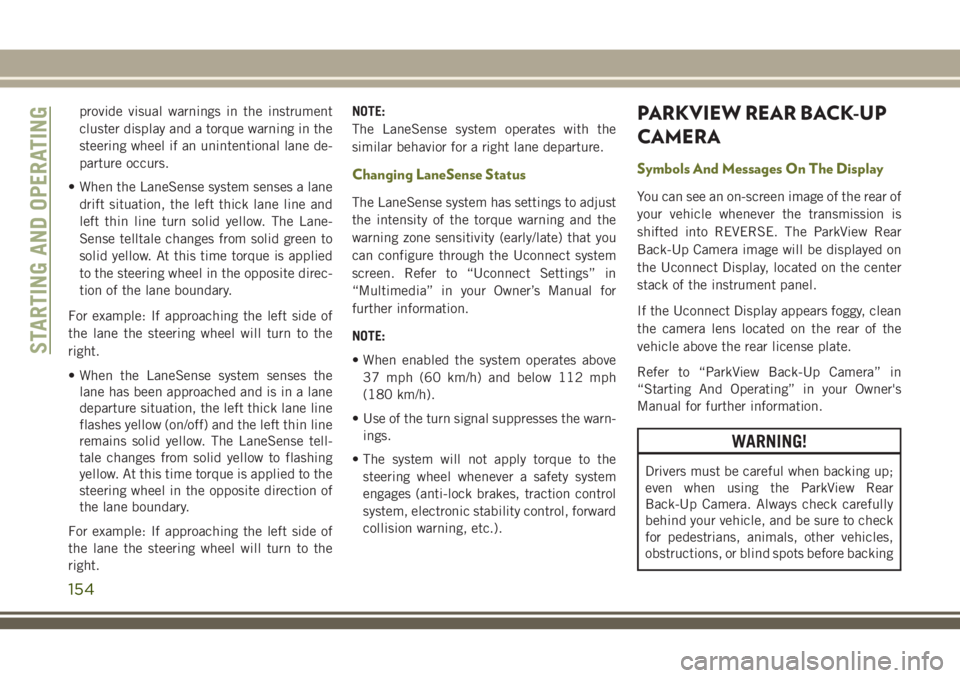
provide visual warnings in the instrument
cluster display and a torque warning in the
steering wheel if an unintentional lane de-
parture occurs.
• When the LaneSense system senses a lane drift situation, the left thick lane line and
left thin line turn solid yellow. The Lane-
Sense telltale changes from solid green to
solid yellow. At this time torque is applied
to the steering wheel in the opposite direc-
tion of the lane boundary.
For example: If approaching the left side of
the lane the steering wheel will turn to the
right.
• When the LaneSense system senses the lane has been approached and is in a lane
departure situation, the left thick lane line
flashes yellow (on/off) and the left thin line
remains solid yellow. The LaneSense tell-
tale changes from solid yellow to flashing
yellow. At this time torque is applied to the
steering wheel in the opposite direction of
the lane boundary.
For example: If approaching the left side of
the lane the steering wheel will turn to the
right. NOTE:
The LaneSense system operates with the
similar behavior for a right lane departure.
Changing LaneSense Status
The LaneSense system has settings to adjust
the intensity of the torque warning and the
warning zone sensitivity (early/late) that you
can configure through the Uconnect system
screen. Refer to “Uconnect Settings” in
“Multimedia” in your Owner’s Manual for
further information.
NOTE:
• When enabled the system operates above
37 mph (60 km/h) and below 112 mph
(180 km/h).
• Use of the turn signal suppresses the warn- ings.
• The system will not apply torque to the steering wheel whenever a safety system
engages (anti-lock brakes, traction control
system, electronic stability control, forward
collision warning, etc.).
PARKVIEW REAR BACK-UP
CAMERA
Symbols And Messages On The Display
You can see an on-screen image of the rear of
your vehicle whenever the transmission is
shifted into REVERSE. The ParkView Rear
Back-Up Camera image will be displayed on
the Uconnect Display, located on the center
stack of the instrument panel.
If the Uconnect Display appears foggy, clean
the camera lens located on the rear of the
vehicle above the rear license plate.
Refer to “ParkView Back-Up Camera” in
“Starting And Operating” in your Owner's
Manual for further information.
WARNING!
Drivers must be careful when backing up;
even when using the ParkView Rear
Back-Up Camera. Always check carefully
behind your vehicle, and be sure to check
for pedestrians, animals, other vehicles,
obstructions, or blind spots before backing
STARTING AND OPERATING
154
Page 162 of 312
HAZARD WARNING
FLASHERS
Control
The Hazard Warning flasher switch is located
on the switch bank just above the climate
controls.
Push the switch to turn on the Hazard Warn-
ing flasher. When the switch is activated, all
directional turn signals will flash on and off towarn oncoming traffic of an emergency. Push
the switch a second time to turn off the
Hazard Warning flashers.
This is an emergency warning system and it
should not be used when the vehicle is in
motion. Use it when your vehicle is disabled
and it is creating a safety hazard for other
motorists.
When you must leave the vehicle to seek
assistance, the Hazard Warning flashers will
continue to operate even though the ignition
is placed in the OFF position. NOTE:
With extended use, the Hazard Warning
flashers may discharge the battery.
BULB REPLACEMENT
Replacement Bulbs
Interior Bulbs
Bulb Number
Cargo Lamp TL212–2
Overhead Console Lamp PLW214–2A Reading Lamp WL212–2
IN CASE OF EMERGENCY
160
Page 163 of 312
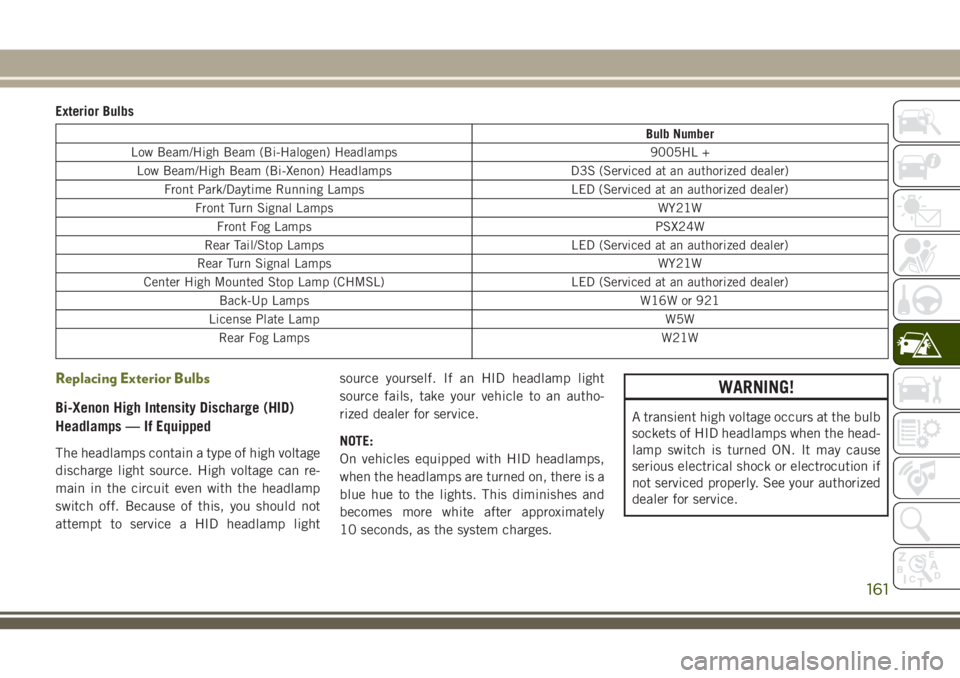
Exterior Bulbs
Bulb Number
Low Beam/High Beam (Bi-Halogen) Headlamps 9005HL + Low Beam/High Beam (Bi-Xenon) Headlamps D3S (Serviced at an authorized dealer) Front Park/Daytime Running Lamps LED (Serviced at an authorized dealer)
Front Turn Signal Lamps WY21WFront Fog Lamps PSX24W
Rear Tail/Stop Lamps LED (Serviced at an authorized dealer)
Rear Turn Signal Lamps WY21W
Center High Mounted Stop Lamp (CHMSL) LED (Serviced at an authorized dealer) Back-Up Lamps W16W or 921
License Plate Lamp W5W Rear Fog Lamps W21W
Replacing Exterior Bulbs
Bi-Xenon High Intensity Discharge (HID)
Headlamps — If Equipped
The headlamps contain a type of high voltage
discharge light source. High voltage can re-
main in the circuit even with the headlamp
switch off. Because of this, you should not
attempt to service a HID headlamp light source yourself. If an HID headlamp light
source fails, take your vehicle to an autho-
rized dealer for service.
NOTE:
On vehicles equipped with HID headlamps,
when the headlamps are turned on, there is a
blue hue to the lights. This diminishes and
becomes more white after approximately
10 seconds, as the system charges.
WARNING!
A transient high voltage occurs at the bulb
sockets of HID headlamps when the head-
lamp switch is turned ON. It may cause
serious electrical shock or electrocution if
not serviced properly. See your authorized
dealer for service.
161
Page 164 of 312
Bi-Halogen Headlamps
1. Remove the three hex head screws fromthe wheel liner.
2. Pull the exterior edge of the liner towards the tire to gain access to the headlamp
bulb cap.
3. Firmly grasp the cap and rotate it counter- clockwise to unlock it.
4. Firmly grasp the bulb and connector as- sembly and rotate counterclockwise to
remove from the housing.
5. Disconnect the bulb from the electrical connector and then connect the replace-
ment bulb.
CAUTION!
Do not touch the new bulb with your fin-
gers. Oil contamination will severely
shorten bulb life. If the bulb comes in
contact with any oily surface, clean the
bulb with rubbing alcohol.
6. Install the bulb and connector assembly into the headlamp housing and rotate
clockwise to lock it in place. 7. Install the bulb cap in the headlamp
housing and rotate clockwise to lock it in
place.
8. Install the three hex head screws into the wheel liner.
Front Turn Signals And Front Side Marker
Lamps
1. Open the hood.
NOTE:
Removal of the air cleaner filter housing
may be necessary prior to replacing bulbs
in the upper lamp assembly on the pas-
senger side of the vehicle.
2. Twist the appropriate bulb and socket assembly counterclockwise, and then re-
move the bulb and socket assembly from
the lamp housing.
3. Pull the bulb out of the socket and insert the replacement bulb.
4. Install the bulb and socket assembly into the housing, and rotate the socket clock-
wise to lock it in place.
5. Re-install air cleaner filter housing if removed.
Front Fog Lamp
1. Remove the three hex head screws from
the wheel liner.
2. Pull the exterior edge of the wheel liner towards the tire to gain access to the bulb.
3. Squeeze the two tabs on the side of the bulb socket and pull straight out from the
fog lamp.
4. Disconnect the wire harness from the bulb.
CAUTION!
Do not touch the new bulb with your fin-
gers. Oil contamination will severely
shorten bulb life. If the bulb comes in
contact with any oily surface, clean the
bulb with rubbing alcohol.
5. Reconnect the wiring harness to the new bulb and reinstall by inserting the new
bulb straight into the fog lamp housing
until it locks in place.
6. Lock the lower door in the wheel liner.
IN CASE OF EMERGENCY
162
Page 253 of 312
Inserting USB/iPod Device
Gently insert the USB/iPod device into the
USB Port. If you insert a USB/iPod device
with the ignition ON, the unit will switch to
USB/iPod mode and begin to play when you
insert the device. The display will show the
track number and index time in minutes and
seconds. Play will begin at the start of track
one.
Browse
Press the “Browse” button on the touch-
screen to select Artist, Albums, Genres,
Songs, Playlists or Folders from the USB/
iPod device. Once the desired selection is
made you can chose from the available media
by pressing the button on the touchscreen.
Press the “Exit” button on the touchscreen if
you wish to cancel the browse function.
AUX Mode
AUX Mode is entered by inserting a AUX
device using a stereo cable with a 3.5 mm
audio jack into the AUX port, or by pushing
the MEDIA button located on the faceplate.
Once in Media Mode, press the “Source”
button on the touchscreen and select “AUX.”Inserting Auxiliary Device
Gently insert the Auxiliary device cable into
the AUX Port. If you insert a Auxiliary device
with the ignition ON, the unit will switch to
AUX mode and begin to play when you insert
the device cable.
Controlling The Auxiliary Device
The control of the Auxiliary device (e.g., se-
lecting playlists, play, fast forward, etc.) can-
not be provided by the radio; use the device
controls instead. Adjust the volume with the
VOLUME/MUTE rotary knob, or with the vol-
ume of the attached device.
The radio unit is acting as the amplifier for
audio output from the Auxiliary device.
Therefore if the volume control on the Auxil-
iary device is set too low, there will be insuf-
ficient audio signal for the radio unit to play
the music on the device.
Track Selection
Seek Up/Seek Down
Press and release the “Right Arrow”but-
ton on the touchscreen for the next selection.
Press and release the “Left Arrow”
button on the touchscreen to return to the beginning
of the current selection, or return to the
beginning of the previous selection if the Disc
is within the first second of the current selec-
tion.
Fast Seek Up
Press and hold the “Right Arrow”button
on the touchscreen and the desired mode will
begin to fast forward through the current
track until the button on the touchscreen is
released.
Fast Seek Down
Press and hold the “Left Arrow”button
on the touchscreen and the desired mode will
begin to rewind through the current track
until the button on the touchscreen is re-
leased.
Info
Press the “Info” button on the touchscreen to
display the current track information. Press
the “X” button on the touchscreen to cancel
this feature.
251
Page 303 of 312
FiltersAir Conditioning ..............44
Engine Oil ................238
Flashers Hazard Warning .............160
Turn Signal ..............32, 64
Turn Signals ...............118
Fluid, Brake .................240
Fluid Capacities ...............237
Fluid Leaks ..................118
Fluid Level Checks Brake ...................209
Engine Oil ................208
Fluids And Lubricants ...........238
Fog Lights ........30, 31, 32, 63, 163
Fog Light Service ..............163
Fog Lights, Rear ...............163
Forward Collision Warning ..........81
Four Wheel Drive ..............130
Freeing A Stuck Vehicle ..........189
Front And Rear ParkSense System . . . .149
Front ParkSense System ..........149
Fuel ......................231
Additives .................233
Ethanol ..................232
Filler Cap (Gas Cap) ..........155
Gasoline .................231 Light
....................62
Materials Added .............233
Octane Rating ..........231, 238
Specifications ..............238
Tank Capacity ..............237
Fuses .....................164
Gas Cap (Fuel Filler Cap) .........155
Gasoline, Clean Air .............232
Gasoline (Fuel) ................231
Gear Ranges .................126
Gear Select Lever Override ........189
Glass
Cleaning ................228
Hands-Free Phone (Uconnect) ......263
Hazard Warning Flasher ..........160
Headlights .................30, 31
Automatic ..............30, 31
Delay ....................31
Time Delay ................31
Head Restraints ................25
Head Rests ...................25
Heated Mirrors .................29
Hill Descent Control .............76
Hill Descent Control Indicator .......76
Hill Start Assist ................70 Hood Release
.................47
Instrument Cluster Instrument Cluster ............55
Instrument Panel Lens Cleaning.....227
Interior Appearance Care ..........227
Intermittent Wipers (Delay Wipers) ....33
Introduction ...................1
Inverter, Power .................52
iPod/USB/MP3 Control Bluetooth Streaming Audio ......263
Jacking Instructions ............174
Jack Location ................173
Jack Operation .........173, 174, 216
Jump Starting ................186
Key Fob Arm The Alarm ..............18
Disarm The Alarm .............18
Keyless Enter-N-Go ..............19
Key, Replacement ...............15
Keys .......................13
Lane Change And Turn Signals .......32
Lane Change Assist ..............32
LaneSense ..................151
301