display JEEP CHEROKEE 2018 Owner handbook (in English)
[x] Cancel search | Manufacturer: JEEP, Model Year: 2018, Model line: CHEROKEE, Model: JEEP CHEROKEE 2018Pages: 312, PDF Size: 4.91 MB
Page 154 of 312
When both lane markings are detected and
the driver unintentionally drifts out of the
lane (no turn signal applied), the LaneSense
system provides a haptic warning in the form
of torque applied to the steering wheel, as
well as a visual warning in the instrument
cluster display, to prompt the driver to remain
within the lane boundaries.
The driver may manually override the haptic
warning by applying torque into the steering
wheel at any time.
When only a single lane marking is detected
and the driver unintentionally drifts across the
lane marking (no turn signal applied), the
LaneSense system provides a visual warning
through the instrument cluster display to
prompt the driver to remain within the lane.
When only a single lane marking is detected, a
haptic (torque) warning will not be provided.
NOTE:
When operating conditions have been met,
the LaneSense system will monitor if thedriver’s hands are on the steering wheel and
provide an audible and visual warning to the
driver when the driver’s hands are not de-
tected on the steering wheel. The system will
cancel if the driver does not return their
hands to the wheel.
Turning LaneSense On Or Off
The default status of LaneSense is “off”.
The LaneSense button is located on the
switch panel below the Uconnect display.
To turn the LaneSense system on, push the
LaneSense button (LED turns off). A “Lane-
Sense On” message is shown in the instru-
ment cluster display.
To turn the LaneSense system off, push the
LaneSense button once (LED turns on).
NOTE:
The LaneSense system will retain the last
system state, on or off, from the last ignition
cycle when the ignition is changed to the
ON/RUN position.
LaneSense Warning Message
The LaneSense system will indicate the cur-
rent lane drift condition through the instru-
ment cluster display.
Base Instrument Cluster Display — If Equipped
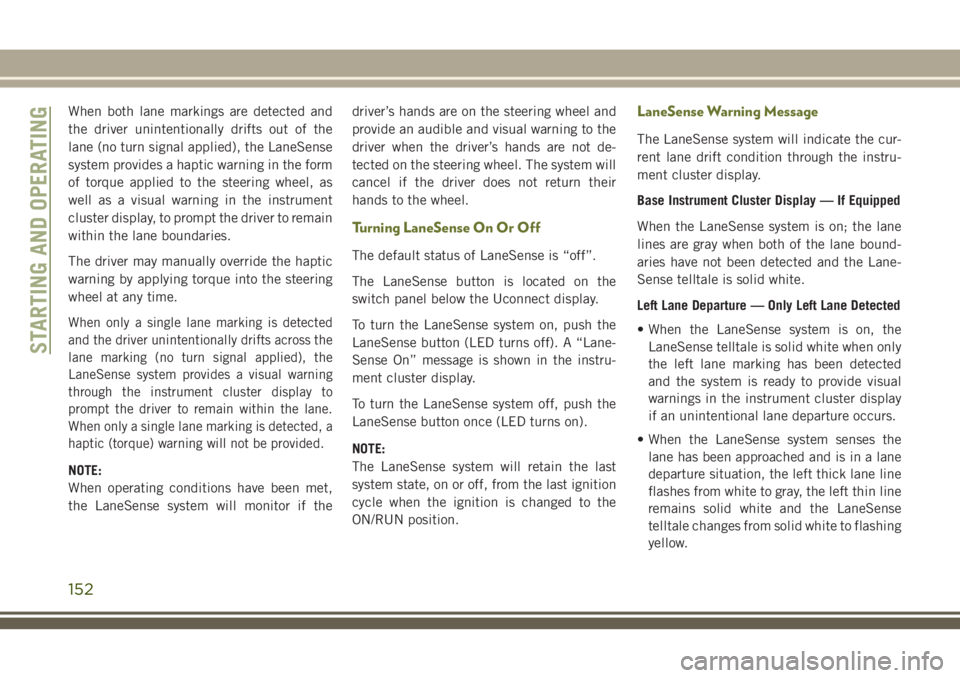
When the LaneSense system is on; the lane
lines are gray when both of the lane bound-
aries have not been detected and the Lane-
Sense telltale is solid white.
Left Lane Departure — Only Left Lane Detected
• When the LaneSense system is on, the
LaneSense telltale is solid white when only
the left lane marking has been detected
and the system is ready to provide visual
warnings in the instrument cluster display
if an unintentional lane departure occurs.
• When the LaneSense system senses the lane has been approached and is in a lane
departure situation, the left thick lane line
flashes from white to gray, the left thin line
remains solid white and the LaneSense
telltale changes from solid white to flashing
yellow.
STARTING AND OPERATING
152
Page 155 of 312
NOTE:
The LaneSense system operates with the
similar behavior for a right lane departure
when only the right lane marking has been
detected.
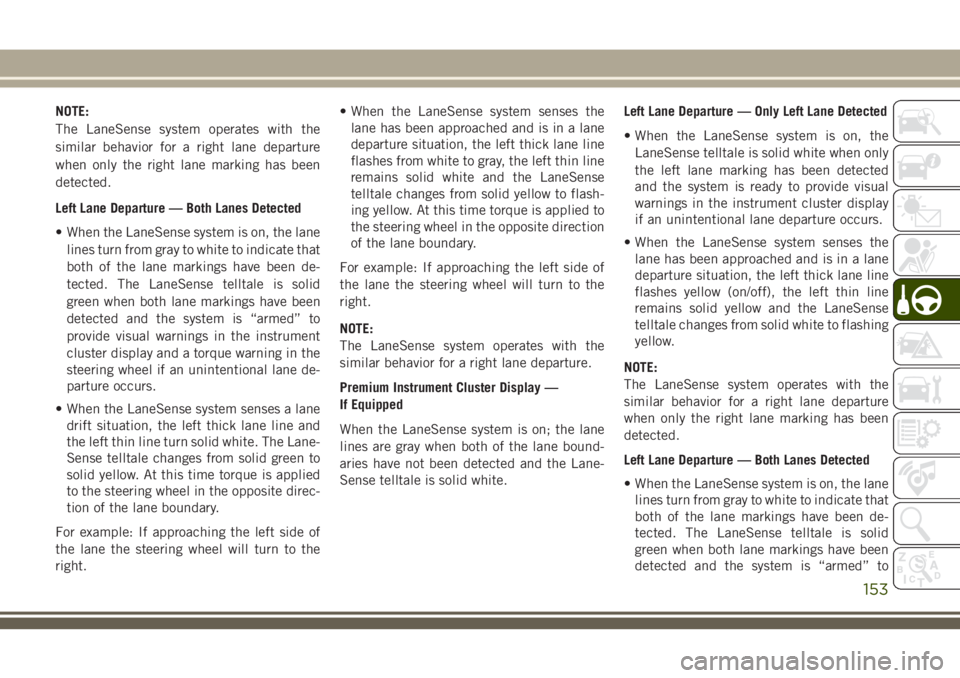
Left Lane Departure — Both Lanes Detected
• When the LaneSense system is on, the lanelines turn from gray to white to indicate that
both of the lane markings have been de-
tected. The LaneSense telltale is solid
green when both lane markings have been
detected and the system is “armed” to
provide visual warnings in the instrument
cluster display and a torque warning in the
steering wheel if an unintentional lane de-
parture occurs.
• When the LaneSense system senses a lane drift situation, the left thick lane line and
the left thin line turn solid white. The Lane-
Sense telltale changes from solid green to
solid yellow. At this time torque is applied
to the steering wheel in the opposite direc-
tion of the lane boundary.
For example: If approaching the left side of
the lane the steering wheel will turn to the
right. • When the LaneSense system senses the
lane has been approached and is in a lane
departure situation, the left thick lane line
flashes from white to gray, the left thin line
remains solid white and the LaneSense
telltale changes from solid yellow to flash-
ing yellow. At this time torque is applied to
the steering wheel in the opposite direction
of the lane boundary.
For example: If approaching the left side of
the lane the steering wheel will turn to the
right.
NOTE:
The LaneSense system operates with the
similar behavior for a right lane departure.
Premium Instrument Cluster Display —
If Equipped
When the LaneSense system is on; the lane
lines are gray when both of the lane bound-
aries have not been detected and the Lane-
Sense telltale is solid white. Left Lane Departure — Only Left Lane Detected
• When the LaneSense system is on, the
LaneSense telltale is solid white when only
the left lane marking has been detected
and the system is ready to provide visual
warnings in the instrument cluster display
if an unintentional lane departure occurs.
• When the LaneSense system senses the lane has been approached and is in a lane
departure situation, the left thick lane line
flashes yellow (on/off), the left thin line
remains solid yellow and the LaneSense
telltale changes from solid white to flashing
yellow.
NOTE:
The LaneSense system operates with the
similar behavior for a right lane departure
when only the right lane marking has been
detected.
Left Lane Departure — Both Lanes Detected
• When the LaneSense system is on, the lane lines turn from gray to white to indicate that
both of the lane markings have been de-
tected. The LaneSense telltale is solid
green when both lane markings have been
detected and the system is “armed” to
153
Page 156 of 312
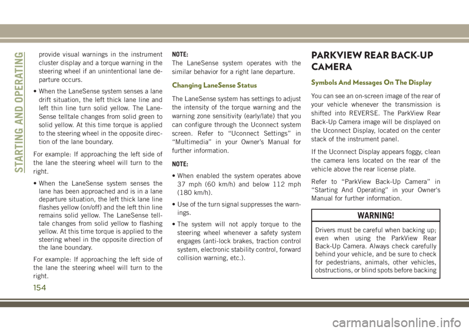
provide visual warnings in the instrument
cluster display and a torque warning in the
steering wheel if an unintentional lane de-
parture occurs.
• When the LaneSense system senses a lane drift situation, the left thick lane line and
left thin line turn solid yellow. The Lane-
Sense telltale changes from solid green to
solid yellow. At this time torque is applied
to the steering wheel in the opposite direc-
tion of the lane boundary.
For example: If approaching the left side of
the lane the steering wheel will turn to the
right.
• When the LaneSense system senses the lane has been approached and is in a lane
departure situation, the left thick lane line
flashes yellow (on/off) and the left thin line
remains solid yellow. The LaneSense tell-
tale changes from solid yellow to flashing
yellow. At this time torque is applied to the
steering wheel in the opposite direction of
the lane boundary.
For example: If approaching the left side of
the lane the steering wheel will turn to the
right. NOTE:
The LaneSense system operates with the
similar behavior for a right lane departure.
Changing LaneSense Status
The LaneSense system has settings to adjust
the intensity of the torque warning and the
warning zone sensitivity (early/late) that you
can configure through the Uconnect system
screen. Refer to “Uconnect Settings” in
“Multimedia” in your Owner’s Manual for
further information.
NOTE:
• When enabled the system operates above
37 mph (60 km/h) and below 112 mph
(180 km/h).
• Use of the turn signal suppresses the warn- ings.
• The system will not apply torque to the steering wheel whenever a safety system
engages (anti-lock brakes, traction control
system, electronic stability control, forward
collision warning, etc.).
PARKVIEW REAR BACK-UP
CAMERA
Symbols And Messages On The Display
You can see an on-screen image of the rear of
your vehicle whenever the transmission is
shifted into REVERSE. The ParkView Rear
Back-Up Camera image will be displayed on
the Uconnect Display, located on the center
stack of the instrument panel.
If the Uconnect Display appears foggy, clean
the camera lens located on the rear of the
vehicle above the rear license plate.
Refer to “ParkView Back-Up Camera” in
“Starting And Operating” in your Owner's
Manual for further information.
WARNING!
Drivers must be careful when backing up;
even when using the ParkView Rear
Back-Up Camera. Always check carefully
behind your vehicle, and be sure to check
for pedestrians, animals, other vehicles,
obstructions, or blind spots before backing
STARTING AND OPERATING
154
Page 198 of 312
SCHEDULED SERVICING
Scheduled Servicing — Gasoline Engine
The scheduled services listed in this manual
must be done at the times or mileages speci-
fied to protect your vehicle warranty and
ensure the best vehicle performance and re-
liability. More frequent maintenance may be
needed for vehicles in severe operating con-
ditions, such as dusty areas and very short
trip driving. Inspection and service should
also be done anytime a malfunction is sus-
pected.
The oil change indicator system will remind
you that it is time to take your vehicle in for
scheduled maintenance.
An “Oil Change Required” will be displayed
in the instrument cluster and a single chime
will sound, indicating that an oil change is
necessary.
The oil change indicator message will illumi-
nate approximately 7,000 miles (11,200 km)
after the most recent oil change was per-
formed. Have your vehicle serviced as soon as
possible, within 500 miles (800 km).
NOTE:
• The oil change indicator message will notmonitor the time since the last oil change.
Change your vehicle’s oil if it has been
12 months since your last oil change even
if the oil change indicator message is NOT
illuminated.
• Change your engine oil more often if you drive your vehicle off-road for an extended
period of time.
• Under no circumstances should oil change intervals exceed 7,500 miles (12,000 km)
or 12 months, whichever comes first.
Your authorized dealer will reset the oil
change indicator message after completing
the scheduled oil change. If this scheduled
oil change is performed by someone other
than your authorized dealer the message can
be reset by referring to the steps described
under ”Instrument Cluster Display” in “Get-
ting To Know Your Instrument Panel” for
further information. Once A Month Or Before A Long Trip
• Check engine oil level.
• Check windshield washer fluid level.
• Check tire pressure and look for unusual
wear or damage. Rotate tires at the first
sign of irregular wear, even if it occurs
before the oil indicator system turns on.
• Check the fluid levels of the coolant reser- voir and brake master cylinder, fill as
needed.
• Check function of all interior and exterior lights.
SERVICING AND MAINTENANCE
196
Page 202 of 312
WARNING!
and the right equipment. If you have any
doubt about your ability to perform a
service job, take your vehicle to a com-
petent mechanic.
• Failure to properly inspect and maintain
your vehicle could result in a component
malfunction and effect vehicle handling
and performance. This could cause an
accident.
Heavy Duty Use Of Vehicle
†† Change the engine oil and engine oil filter
at every 4500 miles (7,500 km) or
12 months if using your vehicle under any of
the following severe duty conditions:
• Stop and go driving.
• Driving in dusty conditions.
• Short trips of less than 10 miles (16 km).
• Trailer towing.
• Taxi, police, or delivery service (commercial
service).
• Off-road or desert operation.
Scheduled Servicing — Diesel Engine
Your vehicle is equipped with an automatic
oil change indicator system. The oil change
indicator system will remind you that it is
time to take your vehicle in for scheduled
maintenance.
Based on engine operation conditions, the oil
change indicator message will illuminate.
This means that service is required for your
vehicle. Operating conditions such as fre-
quent short-trips, trailer tow, extremely hot or
cold ambient temperatures will influence
when the “Oil Change Required” message is
displayed. Severe Operating Conditions can
cause the change oil message to illuminate
as earlier than specified. Have your vehicle
serviced as soon as possible, within the next
500 miles (805 km).
To help you have the best driving experience
possible, the manufacturer has identified the
specific vehicle maintenance service inter-
vals that are required to keep your vehicle
operating properly and safely. The manufacturer recommends that these
maintenance intervals be performed at your
selling dealer. The technicians at your deal-
ership know your vehicle best, and have ac-
cess to factory trained information, genuine
Mopar parts, and specially designed elec-
tronic and mechanical tools that can help
prevent future costly repairs.
The maintenance intervals shown should be
performed as indicated in this section.
NOTE:
•
The actual interval for changing the oil and
replacing the engine oil filter depends on the
vehicle usage conditions, it is signaled by the
warning light or message (if present) in the
instrument panel. It should not exceed
12,500 miles (20,000 km) or 12 months.
• Flush and replace the engine coolant at
120 months or 150,000 miles (240,000 km)
whichever comes first.
SERVICING AND MAINTENANCE
200
Page 245 of 312
MULTIMEDIA
CYBERSECURITY...........245
TIPS CONTROLS AND GENERAL
INFORMATION .............246
Steering Wheel Audio Controls ......246
Reception Conditions ............246
Care And Maintenance ...........246
Anti-Theft Protection ............246
UCONNECT 3 WITH 5-INCH
DISPLAY..................247
Controls On The Front Panel .......247
Clock Setting .................248
Equalizer, Balance And Fade .......248
Radio Mode ..................249
Media Mode .................249
Bluetooth Source ..............252
UCONNECT 3C/3C NAV .......253
Uconnect 3C/3C NAV At A Glance . . .253
Drag & Drop Menu Bar...........255
Radio Mode ..................255
Media Mode .................256
UCONNECT SETTINGS ........256IPOD/USB/SD CARD/MEDIA
PLAYER CONTROL
..........257
Audio Jack (AUX)..............257
USB Port ...................257
SD Card ................... .258
Bluetooth Streaming Audio ........258
NAVIGATION...............258
Changing The Navigation Voice
Prompt Volume ...............258
Finding Points Of Interest .........259
Finding A Place By Spelling
The Name ...................259
One-Step Voice Destination Entry . . . .259
Setting Your Home Location ........259
Go Home ...................260
Adding A Stop ................260
Taking A Detour ...............260
UCONNECT PHONE ..........261
Operation...................261
Uconnect Phone Features .........263
Uconnect Phone (Bluetooth Hands
Free Calling) .................263 Pairing (Wirelessly Connecting)
Your Mobile Phone To The
Uconnect System
..............263
Common Phone Commands
(Examples) ..................266
Mute (Or Unmute) Microphone
During Call ..................266
Transfer Ongoing Call Between
Handset And Vehicle ............266
Phonebook ..................267
Voice Command Tips ............267
Changing The Volume ...........267
Using Do Not Disturb ...........267
Incoming Text Messages .........268
Voice Text Reply (Not Compatible
With iPhone) ................269
Helpful Tips And Common Questions
To Improve Bluetooth Performance
With Your Uconnect System ........270UCONNECT VOICE RECOGNITION
QUICK TIPS................271
Introducing Uconnect ...........271
Get Started .................272
MULTIMEDIA
243
Page 248 of 312
TIPS CONTROLS AND
GENERAL INFORMATION
Steering Wheel Audio Controls
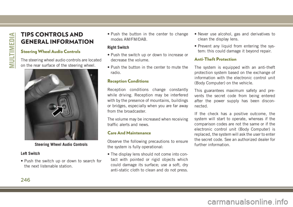
The steering wheel audio controls are located
on the rear surface of the steering wheel.
Left Switch
• Push the switch up or down to search forthe next listenable station. • Push the button in the center to change
modes AM/FM/DAB.
Right Switch
• Push the switch up or down to increase or decrease the volume.
• Push the button in the center to mute the radio.
Reception Conditions
Reception conditions change constantly
while driving. Reception may be interfered
with by the presence of mountains, buildings
or bridges, especially when you are far away
from the broadcaster.
The volume may be increased when receiving
traffic alerts and news.
Care And Maintenance
Observe the following precautions to ensure
the system is fully operational:
• The display lens should not come into con-tact with pointed or rigid objects which
could damage its surface; use a soft, dry
anti-static cloth to clean and do not press. • Never use alcohol, gas and derivatives to
clean the display lens.
• Prevent any liquid from entering the sys- tem: this could damage it beyond repair.
Anti-Theft Protection
The system is equipped with an anti-theft
protection system based on the exchange of
information with the electronic control unit
(Body Computer) on the vehicle.
This guarantees maximum safety and pre-
vents the secret code from being entered
after the power supply has been discon-
nected.
If the check has a positive outcome, the
system will start to operate, whereas if the
comparison codes are not the same or if the
electronic control unit (Body Computer) is
replaced, the system will ask the user to enter
the secret code. See an authorized dealer for
further information.
Steering Wheel Audio Controls
MULTIMEDIA
246
Page 249 of 312
UCONNECT 3 WITH 5-INCH DISPLAY
Controls On The Front Panel
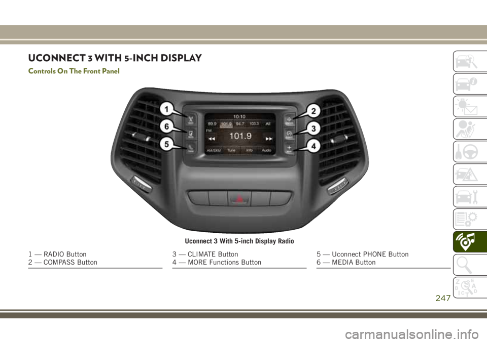
Uconnect 3 With 5-inch Display Radio
1 — RADIO Button
2 — COMPASS Button3 — CLIMATE Button
4 — MORE Functions Button5 — Uconnect PHONE Button
6 — MEDIA Button
247
Page 250 of 312
Clock Setting
To start the clock setting procedure:
1. Push the MORE button on the faceplate.Next press the “Settings” button on the
touchscreen and then press the “Clock
and Date” button on the touchscreen.
2. Press the “Set Time” button on the touchscreen.
3. Press the “Up” or “Down” arrows to ad- just the hours or minutes, next select the
“AM” or “PM” button on the touchscreen.
You can also select 12hr or 24hr format
by pressing the desired button on the
touchscreen.
4. Once the time is set press the “Done” button on the touchscreen to exit the time
screen.
NOTE:
In the Clock Setting Menu you can also select
the “Show Time Status” button on the touch-
screen, then select from “On” or “Off” to
display the time in the status bar.
Equalizer, Balance And Fade
1. Push the MORE button on the faceplate. Next press the “Settings” button on the
touchscreen.
2. Then scroll down and press the “Audio” button on the touchscreen to get to the
Audio menu.
3. The Audio Menu shows the following op- tions for you to customize your audio
settings.
Equalizer
Press the “Equalizer” button on the touch-
screen to adjust the Bass, Mid and Treble.
Use the “+” or “–” button on the touchscreen
to adjust the equalizer to your desired set-
tings. Press the “Back Arrow” button on the
touchscreen when done.
Balance/Fade
Press the “Balance/Fade” button on the
touchscreen to adjust the sound from the
speakers. Use the arrow button on the touch-
screen to adjust the sound level from the
front and rear or right and left side speakers.
Press the Center “C” button on the touch- screen to reset the balance and fade to the
factory setting. Press the “Back Arrow” but-
ton on the touchscreen when done.
Speed Adjusted Volume
Press the “Speed Adjusted Volume” button
on the touchscreen to select between OFF, 1,
2 or 3. This will decrease the radio volume
relative to a decrease in vehicle speed. Press
the “Back Arrow” button on the touchscreen
when done.
Loudness
Press the “Loudness” button on the touch-
screen to select the Loudness feature. When
this feature is activated it improves sound
quality at lower volumes.
Surround Sound
Press the “Surround Sound” button on the
touchscreen, select “On” or “Off” followed
by pressing the “Back Arrow” button on the
touchscreen. When this feature is activated,
it provides simulated surround sound mode.
MULTIMEDIA
248
Page 251 of 312
Radio Mode
Seek Previous/Next Buttons
Seek Up
Press and release the “Seek Up”button
on the touchscreen to tune the radio to the
next listenable station or channel.
During a Seek Up function, if the radio
reaches the starting station after passing
through the entire band two times, the radio
will stop at the station where it began.
Fast Seek Up
Press and hold the “Seek Up”button on
the touchscreen to advance the radio through
the available stations or channels at a faster
rate, the radio stops at the next available
station or channel when the button on the
touchscreen is released.
Seek Down
Press and release the “Seek Down”but-
ton on the touchscreen to tune the radio to
the next listenable station or channel. During a Seek Down function, if the radio
reaches the starting station after passing
through the entire band two times, the radio
will stop at the station where it began.
Fast Seek Down
Press and hold the “Seek Down”button
on the touchscreen to advance the radio
through the available stations or channel at a
faster rate, the radio stops at the next avail-
able station or channel when the button on
the touchscreen is released.
Store Radio Presets
The Radio stores up to 12 presets in each of
the Radio modes. There are four visible pre-
sets at the top of the radio screen. Pressing
the “All” button on the touchscreen on the
radio home screen will display all of the
preset stations for that mode.
To store a radio preset manually, follow the
steps below:
1. Tune to the desired station. 2. Press and hold the desired numbered but-
ton on the touchscreen for more than two
seconds or until you hear a confirmation
beep.
Media Mode
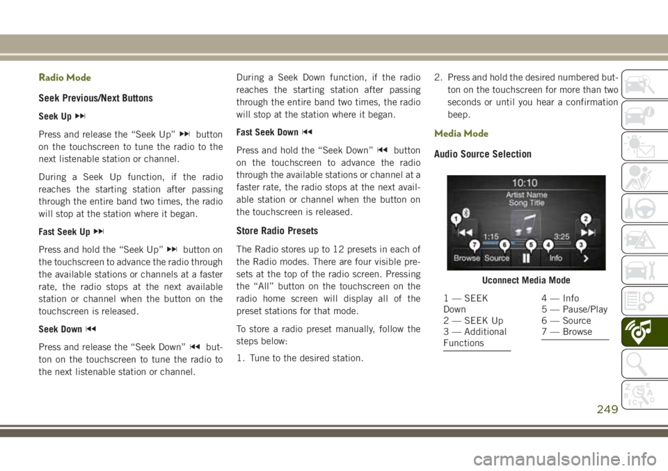
Audio Source Selection
Uconnect Media Mode
1 — SEEK
Down
2 — SEEK Up
3 — Additional
Functions4 — Info
5 — Pause/Play
6 — Source
7 — Browse
249