headlamp JEEP CHEROKEE 2018 Owner handbook (in English)
[x] Cancel search | Manufacturer: JEEP, Model Year: 2018, Model line: CHEROKEE, Model: JEEP CHEROKEE 2018Pages: 312, PDF Size: 4.91 MB
Page 32 of 312
EXTERIOR LIGHTS
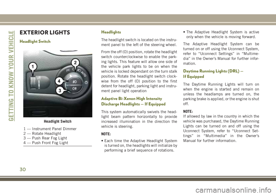
Headlight SwitchHeadlightsThe headlight switch is located on the instru-
ment panel to the left of the steering wheel.
From the off (O) position, rotate the headlight
switch counterclockwise to enable the park-
ing lights. This feature will allow one side of
the vehicle park lights to be on when the
vehicle is locked dependant on the turn stalk
position. Rotate the headlight switch clock-
wise from the off (O) position to the first
detent for headlight, parking light and instru-
ment panel light operation
Adaptive Bi-Xenon High Intensity
Discharge Headlights — If Equipped
This system automatically swivels the head-
light beam pattern horizontally to provide
increased illumination in the direction the
vehicle is steering.
NOTE:
• Each time the Adaptive Headlight System
is turned on, the headlights will initialize by
performing a brief sequence of rotations. • The Adaptive Headlight System is active
only when the vehicle is moving forward.
The Adaptive Headlight System can be
turned on or off using the Uconnect System,
refer to “Uconnect Settings” in “Multime-
dia” in the Owner’s Manual for further infor-
mation.
Daytime Running Lights (DRL) —
If Equipped
The Daytime Running Lights will turn on
when the engine is started and remain on
unless the headlamps are turned on, the
parking brake is applied, or the engine is shut
off.
NOTE:
If allowed by law in the country in which the
vehicle was purchased, the Daytime Running
Lights can be turned on and off using the
Uconnect System, refer to “Uconnect Set-
tings” in “Multimedia” in the Owner’s
Manual for further information.
Headlight Switch
1 — Instrument Panel Dimmer
2 — Rotate Headlight
3 — Push Rear Fog Light
4 — Push Front Fog Light
GETTING TO KNOW YOUR VEHICLE
30
Page 105 of 312
Your vehicle may also be designed to perform
any of these other functions in response to
the Enhanced Accident Response System:
• Turn off the Fuel Filter Heater, Turn off theHVAC Blower Motor, Close the HVAC Circu-
lation Door
• Cut off battery power to the: – Engine
– Electric Motor (if equipped)
– Electric power steering
– Brake booster
– Electric park brake
– Automatic transmission gear selector
– Horn
– Front wiper
– Headlamp washer pump NOTE:
After an accident, remember to cycle the
ignition to the STOP (OFF/LOCK) position
and remove the key from the ignition switch
to avoid draining the battery. Carefully check
the vehicle for fuel leaks in the engine com-
partment and on the ground near the engine
compartment and fuel tank before resetting
the system and starting the engine. If there
are no fuel leaks or damage to the vehicle
electrical devices (e.g. headlights) after an
accident, reset the system by following the
procedure described below.
Enhanced Accident Response System Reset
Procedure
In order to reset the Enhanced Accident Re-
sponse System functions after an event, the
ignition switch must be changed from igni-
tion START or ON/RUN to ignition OFF. Care-
fully check the vehicle for fuel leaks in the
engine compartment and on the ground near
the engine compartment and fuel tank before
resetting the system and starting the engine.
Maintaining Your Air Bag System
WARNING!
•Modifications to any part of the air bag
system could cause it to fail when you
need it. You could be injured if the air bag
system is not there to protect you. Do not
modify the components or wiring, includ-
ing adding any kind of badges or stickers
to the steering wheel hub trim cover or the
upper right side of the instrument panel.
Do not modify the front bumper, vehicle
body structure, or add aftermarket side
steps or running boards.
• It is dangerous to try to repair any part of
the air bag system yourself. Be sure to
tell anyone who works on your vehicle
that it has an air bag system.
• Do not attempt to modify any part of your
air bag system. The air bag may inflate
accidentally or may not function prop-
erly if modifications are made. Take your
vehicle to an authorized dealer for any
air bag system service. If your seat, in-
cluding your trim cover and cushion,
needs to be serviced in any way (includ-
103
Page 163 of 312
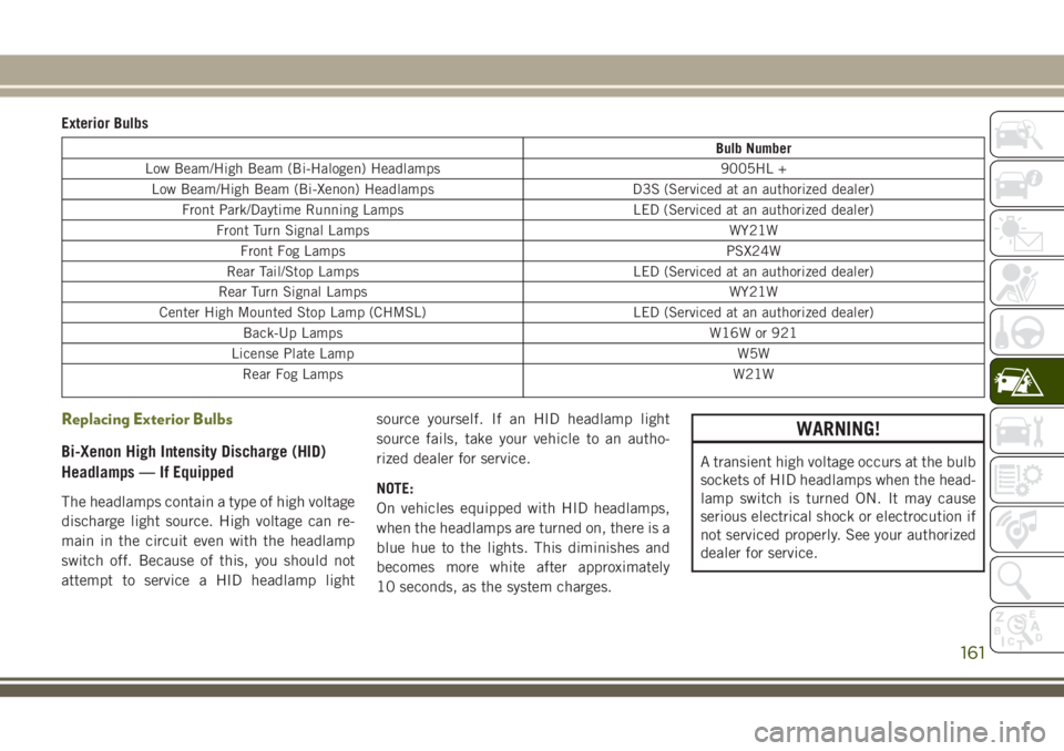
Exterior Bulbs
Bulb Number
Low Beam/High Beam (Bi-Halogen) Headlamps 9005HL + Low Beam/High Beam (Bi-Xenon) Headlamps D3S (Serviced at an authorized dealer) Front Park/Daytime Running Lamps LED (Serviced at an authorized dealer)
Front Turn Signal Lamps WY21WFront Fog Lamps PSX24W
Rear Tail/Stop Lamps LED (Serviced at an authorized dealer)
Rear Turn Signal Lamps WY21W
Center High Mounted Stop Lamp (CHMSL) LED (Serviced at an authorized dealer) Back-Up Lamps W16W or 921
License Plate Lamp W5W Rear Fog Lamps W21W
Replacing Exterior Bulbs
Bi-Xenon High Intensity Discharge (HID)
Headlamps — If Equipped
The headlamps contain a type of high voltage
discharge light source. High voltage can re-
main in the circuit even with the headlamp
switch off. Because of this, you should not
attempt to service a HID headlamp light source yourself. If an HID headlamp light
source fails, take your vehicle to an autho-
rized dealer for service.
NOTE:
On vehicles equipped with HID headlamps,
when the headlamps are turned on, there is a
blue hue to the lights. This diminishes and
becomes more white after approximately
10 seconds, as the system charges.
WARNING!
A transient high voltage occurs at the bulb
sockets of HID headlamps when the head-
lamp switch is turned ON. It may cause
serious electrical shock or electrocution if
not serviced properly. See your authorized
dealer for service.
161
Page 164 of 312
Bi-Halogen Headlamps
1. Remove the three hex head screws fromthe wheel liner.
2. Pull the exterior edge of the liner towards the tire to gain access to the headlamp
bulb cap.
3. Firmly grasp the cap and rotate it counter- clockwise to unlock it.
4. Firmly grasp the bulb and connector as- sembly and rotate counterclockwise to
remove from the housing.
5. Disconnect the bulb from the electrical connector and then connect the replace-
ment bulb.
CAUTION!
Do not touch the new bulb with your fin-
gers. Oil contamination will severely
shorten bulb life. If the bulb comes in
contact with any oily surface, clean the
bulb with rubbing alcohol.
6. Install the bulb and connector assembly into the headlamp housing and rotate
clockwise to lock it in place. 7. Install the bulb cap in the headlamp
housing and rotate clockwise to lock it in
place.
8. Install the three hex head screws into the wheel liner.
Front Turn Signals And Front Side Marker
Lamps
1. Open the hood.
NOTE:
Removal of the air cleaner filter housing
may be necessary prior to replacing bulbs
in the upper lamp assembly on the pas-
senger side of the vehicle.
2. Twist the appropriate bulb and socket assembly counterclockwise, and then re-
move the bulb and socket assembly from
the lamp housing.
3. Pull the bulb out of the socket and insert the replacement bulb.
4. Install the bulb and socket assembly into the housing, and rotate the socket clock-
wise to lock it in place.
5. Re-install air cleaner filter housing if removed.
Front Fog Lamp
1. Remove the three hex head screws from
the wheel liner.
2. Pull the exterior edge of the wheel liner towards the tire to gain access to the bulb.
3. Squeeze the two tabs on the side of the bulb socket and pull straight out from the
fog lamp.
4. Disconnect the wire harness from the bulb.
CAUTION!
Do not touch the new bulb with your fin-
gers. Oil contamination will severely
shorten bulb life. If the bulb comes in
contact with any oily surface, clean the
bulb with rubbing alcohol.
5. Reconnect the wiring harness to the new bulb and reinstall by inserting the new
bulb straight into the fog lamp housing
until it locks in place.
6. Lock the lower door in the wheel liner.
IN CASE OF EMERGENCY
162
Page 169 of 312
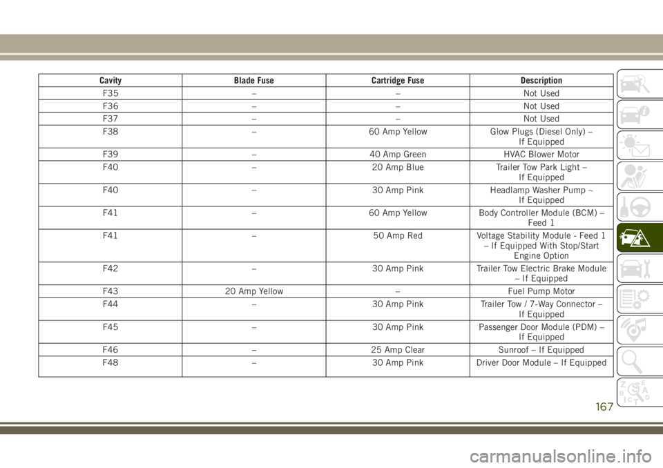
CavityBlade Fuse Cartridge Fuse Description
F35 ––Not Used
F36 ––Not Used
F37 ––Not Used
F38 –60 Amp Yellow Glow Plugs (Diesel Only) –
If Equipped
F39 –40 Amp Green HVAC Blower Motor
F40 –20 Amp Blue Trailer Tow Park Light –
If Equipped
F40 –30 Amp PinkHeadlamp Washer Pump –
If Equipped
F41 –60 Amp YellowBody Controller Module (BCM) –
Feed 1
F41 –50 Amp RedVoltage Stability Module - Feed 1
– If Equipped With Stop/Start Engine Option
F42 –30 Amp PinkTrailer Tow Electric Brake Module
– If Equipped
F43 20 Amp Yellow –Fuel Pump Motor
F44 –30 Amp PinkTrailer Tow / 7-Way Connector –
If Equipped
F45 –30 Amp PinkPassenger Door Module (PDM) –
If Equipped
F46 –25 Amp Clear Sunroof – If Equipped
F48 –30 Amp PinkDriver Door Module – If Equipped
167
Page 172 of 312
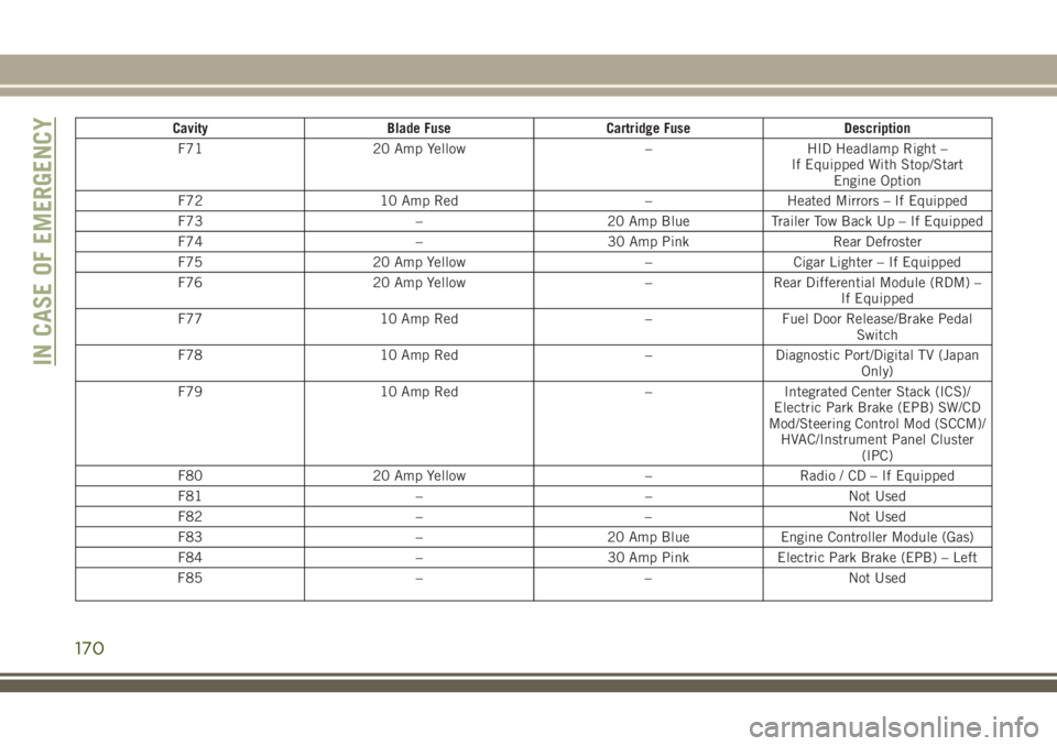
CavityBlade Fuse Cartridge Fuse Description
F71 20 Amp Yellow –HID Headlamp Right –
If Equipped With Stop/Start Engine Option
F72 10 Amp Red –Heated Mirrors – If Equipped
F73 –20 Amp BlueTrailer Tow Back Up – If Equipped
F74 –30 Amp Pink Rear Defroster
F75 20 Amp Yellow –Cigar Lighter – If Equipped
F76 20 Amp Yellow –Rear Differential Module (RDM) –
If Equipped
F77 10 Amp Red –Fuel Door Release/Brake Pedal
Switch
F78 10 Amp Red –Diagnostic Port/Digital TV (Japan
Only)
F79 10 Amp Red –Integrated Center Stack (ICS)/
Electric Park Brake (EPB) SW/CD
Mod/Steering Control Mod (SCCM)/ HVAC/Instrument Panel Cluster (IPC)
F80 20 Amp Yellow –Radio / CD – If Equipped
F81 ––Not Used
F82 ––Not Used
F83 –20 Amp BlueEngine Controller Module (Gas)
F84 –30 Amp PinkElectric Park Brake (EPB) – Left
F85 ––Not Used
IN CASE OF EMERGENCY
170
Page 173 of 312
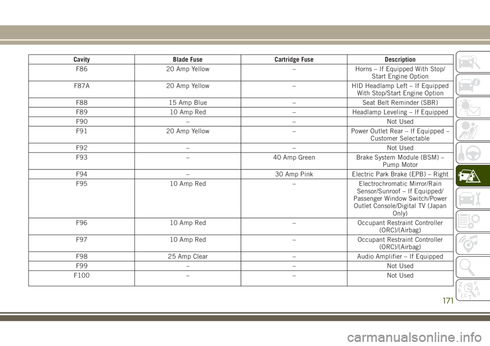
CavityBlade Fuse Cartridge Fuse Description
F86 20 Amp Yellow –Horns – If Equipped With Stop/
Start Engine Option
F87A 20 Amp Yellow –HID Headlamp Left – If Equipped
With Stop/Start Engine Option
F88 15 Amp Blue –Seat Belt Reminder (SBR)
F89 10 Amp Red –Headlamp Leveling – If Equipped
F90 ––Not Used
F91 20 Amp Yellow –Power Outlet Rear – If Equipped –
Customer Selectable
F92 ––Not Used
F93 –40 Amp GreenBrake System Module (BSM) –
Pump Motor
F94 –30 Amp PinkElectric Park Brake (EPB) – Right
F95 10 Amp Red –Electrochromatic Mirror/Rain
Sensor/Sunroof – If Equipped/
Passenger Window Switch/Power Outlet Console/Digital TV (Japan Only)
F96 10 Amp Red –Occupant Restraint Controller
(ORC)/(Airbag)
F97 10 Amp Red –Occupant Restraint Controller
(ORC)/(Airbag)
F98 25 Amp Clear –Audio Amplifier – If Equipped
F99 ––Not Used
F100 ––Not Used
171