parking brake JEEP CHEROKEE 2018 Owner handbook (in English)
[x] Cancel search | Manufacturer: JEEP, Model Year: 2018, Model line: CHEROKEE, Model: JEEP CHEROKEE 2018Pages: 312, PDF Size: 4.91 MB
Page 18 of 312
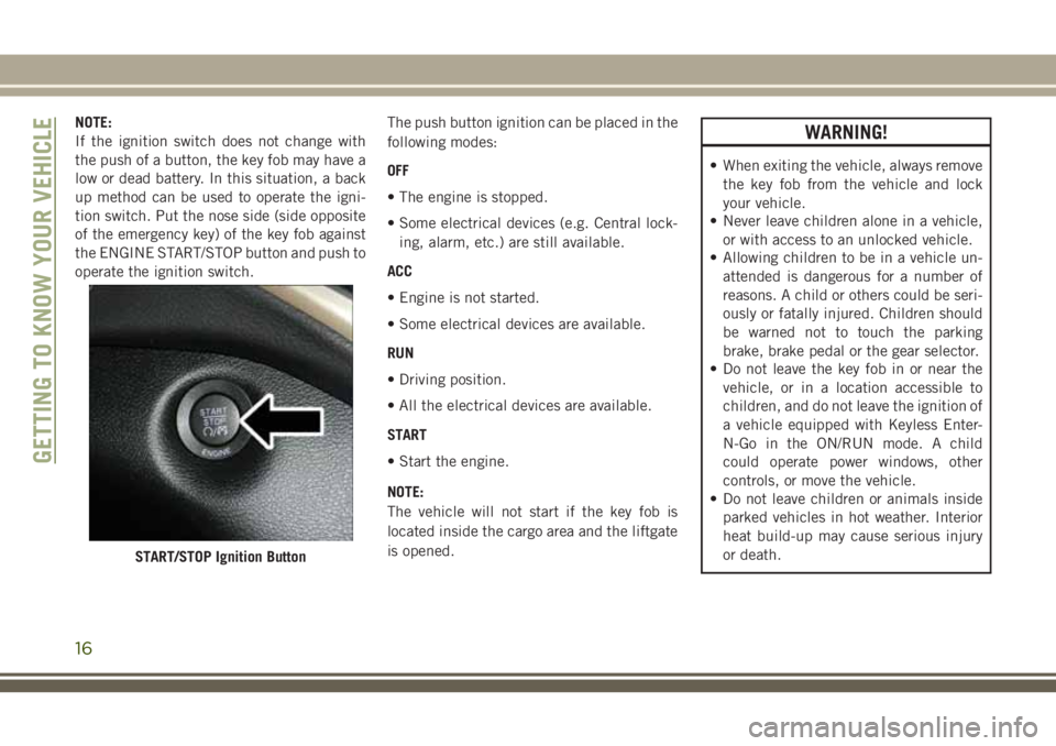
NOTE:
If the ignition switch does not change with
the push of a button, the key fob may have a
low or dead battery. In this situation, a back
up method can be used to operate the igni-
tion switch. Put the nose side (side opposite
of the emergency key) of the key fob against
the ENGINE START/STOP button and push to
operate the ignition switch.The push button ignition can be placed in the
following modes:
OFF
• The engine is stopped.
• Some electrical devices (e.g. Central lock-
ing, alarm, etc.) are still available.
ACC
• Engine is not started.
• Some electrical devices are available.
RUN
• Driving position.
• All the electrical devices are available.
START
• Start the engine.
NOTE:
The vehicle will not start if the key fob is
located inside the cargo area and the liftgate
is opened.WARNING!
• When exiting the vehicle, always remove the key fob from the vehicle and lock
your vehicle.
• Never leave children alone in a vehicle,
or with access to an unlocked vehicle.
• Allowing children to be in a vehicle un-
attended is dangerous for a number of
reasons. A child or others could be seri-
ously or fatally injured. Children should
be warned not to touch the parking
brake, brake pedal or the gear selector.
• Do not leave the key fob in or near the
vehicle, or in a location accessible to
children, and do not leave the ignition of
a vehicle equipped with Keyless Enter-
N-Go in the ON/RUN mode. A child
could operate power windows, other
controls, or move the vehicle.
• Do not leave children or animals inside
parked vehicles in hot weather. Interior
heat build-up may cause serious injury
or death.
START/STOP Ignition Button
GETTING TO KNOW YOUR VEHICLE
16
Page 32 of 312
EXTERIOR LIGHTS
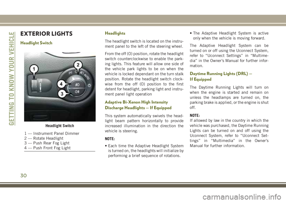
Headlight SwitchHeadlightsThe headlight switch is located on the instru-
ment panel to the left of the steering wheel.
From the off (O) position, rotate the headlight
switch counterclockwise to enable the park-
ing lights. This feature will allow one side of
the vehicle park lights to be on when the
vehicle is locked dependant on the turn stalk
position. Rotate the headlight switch clock-
wise from the off (O) position to the first
detent for headlight, parking light and instru-
ment panel light operation
Adaptive Bi-Xenon High Intensity
Discharge Headlights — If Equipped
This system automatically swivels the head-
light beam pattern horizontally to provide
increased illumination in the direction the
vehicle is steering.
NOTE:
• Each time the Adaptive Headlight System
is turned on, the headlights will initialize by
performing a brief sequence of rotations. • The Adaptive Headlight System is active
only when the vehicle is moving forward.
The Adaptive Headlight System can be
turned on or off using the Uconnect System,
refer to “Uconnect Settings” in “Multime-
dia” in the Owner’s Manual for further infor-
mation.
Daytime Running Lights (DRL) —
If Equipped
The Daytime Running Lights will turn on
when the engine is started and remain on
unless the headlamps are turned on, the
parking brake is applied, or the engine is shut
off.
NOTE:
If allowed by law in the country in which the
vehicle was purchased, the Daytime Running
Lights can be turned on and off using the
Uconnect System, refer to “Uconnect Set-
tings” in “Multimedia” in the Owner’s
Manual for further information.
Headlight Switch
1 — Instrument Panel Dimmer
2 — Rotate Headlight
3 — Push Rear Fog Light
4 — Push Front Fog Light
GETTING TO KNOW YOUR VEHICLE
30
Page 58 of 312
WARNING LIGHTS AND
MESSAGES
The warning/indicator lights will illuminate in
the instrument panel together with a dedi-
cated message and/or acoustic signal when
applicable. These indications are indicative
and precautionary and as such must not be
considered as exhaustive and/or alternative
to the information contained in the Owner’s
Manual, which you are advised to read care-
fully in all cases. Always refer to the informa-
tion in this chapter in the event of a failure
indication. All active telltales will display first
if applicable. The system check menu may
appear different based upon equipment op-
tions and current vehicle status. Some tell-
tales are optional and may not appear.
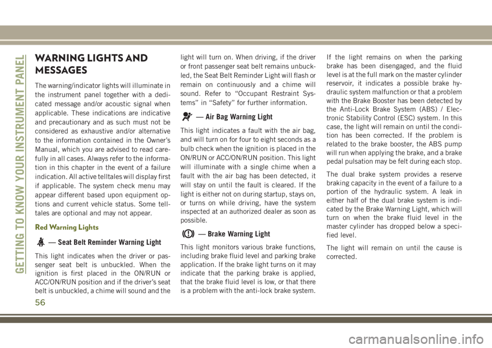
Red Warning Lights
— Seat Belt Reminder Warning Light
This light indicates when the driver or pas-
senger seat belt is unbuckled. When the
ignition is first placed in the ON/RUN or
ACC/ON/RUN position and if the driver’s seat
belt is unbuckled, a chime will sound and thelight will turn on. When driving, if the driver
or front passenger seat belt remains unbuck-
led, the Seat Belt Reminder Light will flash or
remain on continuously and a chime will
sound. Refer to “Occupant Restraint Sys-
tems” in “Safety” for further information.
— Air Bag Warning Light
This light indicates a fault with the air bag,
and will turn on for four to eight seconds as a
bulb check when the ignition is placed in the
ON/RUN or ACC/ON/RUN position. This light
will illuminate with a single chime when a
fault with the air bag has been detected, it
will stay on until the fault is cleared. If the
light is either not on during startup, stays on,
or turns on while driving, have the system
inspected at an authorized dealer as soon as
possible.
— Brake Warning Light
This light monitors various brake functions,
including brake fluid level and parking brake
application. If the brake light turns on it may
indicate that the parking brake is applied,
that the brake fluid level is low, or that there
is a problem with the anti-lock brake system.
If the light remains on when the parking
brake has been disengaged, and the fluid
level is at the full mark on the master cylinder
reservoir, it indicates a possible brake hy-
draulic system malfunction or that a problem
with the Brake Booster has been detected by
the Anti-Lock Brake System (ABS) / Elec-
tronic Stability Control (ESC) system. In this
case, the light will remain on until the condi-
tion has been corrected. If the problem is
related to the brake booster, the ABS pump
will run when applying the brake, and a brake
pedal pulsation may be felt during each stop.
The dual brake system provides a reserve
braking capacity in the event of a failure to a
portion of the hydraulic system. A leak in
either half of the dual brake system is indi-
cated by the Brake Warning Light, which will
turn on when the brake fluid level in the
master cylinder has dropped below a speci-
fied level.
The light will remain on until the cause is
corrected.
GETTING TO KNOW YOUR INSTRUMENT PANEL
56
Page 59 of 312
NOTE:
The light may flash momentarily during sharp
cornering maneuvers, which change fluid
level conditions. The vehicle should have
service performed, and the brake fluid level
checked.
If brake failure is indicated, immediate repair
is necessary.
WARNING!
Driving a vehicle with the red brake light
on is dangerous. Part of the brake system
may have failed. It will take longer to stop
the vehicle. You could have a collision.
Have the vehicle checked immediately.
Vehicles equipped with the Anti-Lock Brake
System (ABS) are also equipped with Elec-
tronic Brake Force Distribution (EBD). In the
event of an EBD failure, the Brake Warning
Light will turn on along with the ABS Light.
Immediate repair to the ABS system is re-
quired. Operation of the Brake Warning Light can be
checked by turning the ignition switch from
the OFF position to the ON/RUN position.
The light should illuminate for approximately
four seconds. The light should then turn off
unless the parking brake is applied or a brake
fault is detected. If the light does not illumi-
nate, have the light inspected by an autho-
rized dealer.
The light also will turn on when the parking
brake is applied with the ignition switch in
the ON/RUN position.
NOTE:
This light shows only that the parking brake is
applied. It does not show the degree of brake
application.
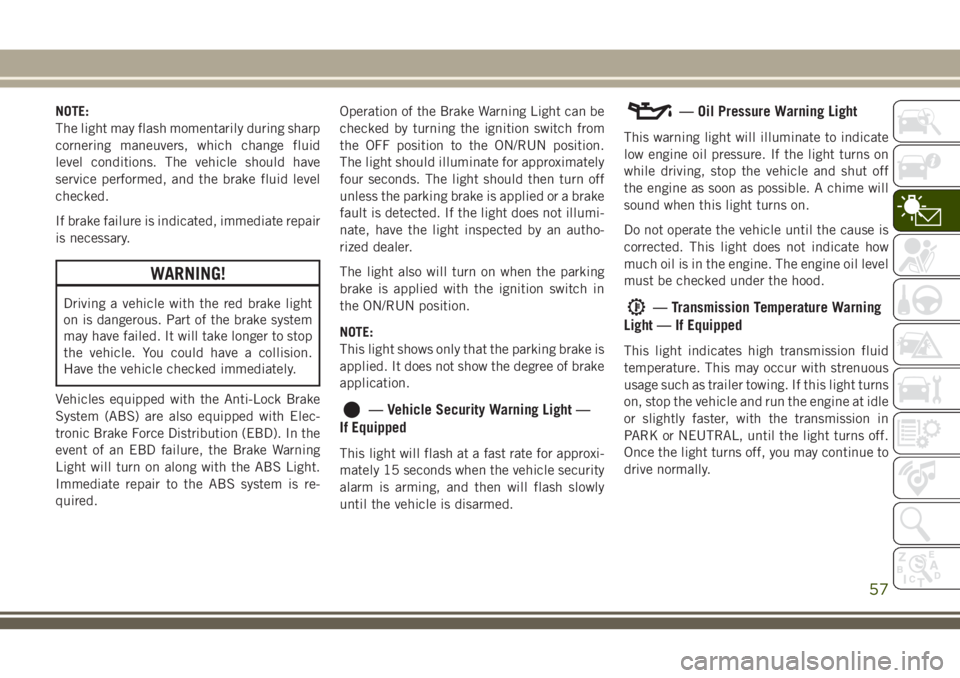
— Vehicle Security Warning Light —
If Equipped
This light will flash at a fast rate for approxi-
mately 15 seconds when the vehicle security
alarm is arming, and then will flash slowly
until the vehicle is disarmed.
— Oil Pressure Warning Light
This warning light will illuminate to indicate
low engine oil pressure. If the light turns on
while driving, stop the vehicle and shut off
the engine as soon as possible. A chime will
sound when this light turns on.
Do not operate the vehicle until the cause is
corrected. This light does not indicate how
much oil is in the engine. The engine oil level
must be checked under the hood.
— Transmission Temperature Warning
Light — If Equipped
This light indicates high transmission fluid
temperature. This may occur with strenuous
usage such as trailer towing. If this light turns
on, stop the vehicle and run the engine at idle
or slightly faster, with the transmission in
PARK or NEUTRAL, until the light turns off.
Once the light turns off, you may continue to
drive normally.
57
Page 73 of 312
For vehicles not equipped with an instrument
cluster display, perform the following steps:
1. Center the steering wheel (front wheelspointing straight forward).
2. Shift the transmission into PARK.
3. Apply the parking brake.
4. Start the engine.
5. Rotate the steering wheel slightly more than one-half turn to the left.
6. Push the “ESC Off” button located in the lower switch bank below the climate con-
trol four times within 20 seconds. The
“ESC Off Indicator Light” should turn on
and turn off two times.
7. Rotate the steering wheel back to center and then an additional slightly more than
one-half turn to the right.
8. Turn the ignition to the OFF mode and then back to ON. If the sequence was
completed properly, the “ESC Off Indica-
tor Light” will blink several times to con-
firm HSA is disabled.
9. Repeat these steps if you want to return this feature to its previous setting.Towing With HSA
HSA will also provide assistance to mitigate
roll back while towing a trailer.
WARNING!
• If you use a trailer brake controller withyour trailer, the trailer brakes may be
activated and deactivated with the brake
switch. If so, there may not be enough
brake pressure to hold both the vehicle
and the trailer on a hill when the brake
pedal is released. In order to avoid roll-
ing down an incline while resuming ac-
celeration, manually activate the trailer
brake or apply more vehicle brake pres-
sure prior to releasing the brake pedal.
• HSA is not a parking brake. Always apply
the parking brake fully when exiting your
vehicle. Also, be certain to place the
transmission in PARK.
• Failure to follow these warnings can re-
sult in a collision or serious personal
injury.
Traction Control System (TCS)
This system monitors the amount of wheel
spin of each of the driven wheels. If wheel
spin is detected, the TCS may apply brake
pressure to the spinning wheel(s) and/or re-
duce engine power to provide enhanced ac-
celeration and stability. A feature of the TCS,
Brake Limited Differential (BLD), functions
similar to a limited slip differential and con-
trols the wheel spin across a driven axle. If
one wheel on a driven axle is spinning faster
than the other, the system will apply the
brake of the spinning wheel. This will allow
more engine torque to be applied to the wheel
that is not spinning. BLD may remain en-
abled even if TCS and ESC are in a reduced
mode.
Electronic Stability Control (ESC)
This system enhances directional control and
stability of the vehicle under various driving
conditions. ESC corrects for oversteering or
understeering of the vehicle by applying the
brake of the appropriate wheel(s) to assist in
counteracting the oversteer or understeer
condition. Engine power may also be reduced
to help the vehicle maintain the desired path.
71
Page 78 of 312
Dynamic Steering Torque (DST)
Dynamic Steering Torque is a feature of the
ESC and Electric Power Steering (EPS) mod-
ules that provides torque at the steering
wheel for certain driving conditions in which
the ESC module is detecting vehicle instabil-
ity. The torque that the steering wheel re-
ceives is only meant to help the driver realize
optimal steering behavior in order to reach/
maintain vehicle stability. The only notifica-
tion the driver receives that the feature is
active is the torque applied to the steering
wheel.
NOTE:
The DST feature is only meant to help the
driver realize the correct course of action
through small torques on the steering wheel,
which means the effectiveness of the DST
feature is highly dependent on the driver’s
sensitivity and overall reaction to the applied
torque. It is very important to realize that this
feature will not steer the vehicle, meaning
the driver is still responsible for steering the
vehicle.
Hill Descent Control (HDC) — If Equipped
HDC is intended for low speed off road driv-
ing while in 4WD Low Range. HDC maintains
vehicle speed while descending hills during
various driving situations. HDC controls ve-
hicle speed by actively controlling the brakes.
HDC Has Three States:
1. Off (feature is not enabled and will notactivate).
2. Enabled (feature is enabled and ready but activation conditions are not met, or
driver is actively overriding with brake or
throttle application).
3. Active (feature is enabled and actively controlling vehicle speed).
Enabling HDC
HDC is enabled by pushing the HDC switch,
but the following conditions must also be met
to enable HDC:
• Driveline is in 4WD Low Range.
• Vehicle speed is below 5 mph (8 km/h).
• Parking brake is released.
• Driver door is closed. Activating HDC
Once HDC is enabled it will activate auto-
matically if driven down a grade of sufficient
magnitude. The set speed for HDC is select-
able by the driver, and can be adjusted by
using the gear shift +/-. The following sum-
marizes the HDC set speeds:
HDC Target Set Speeds
• P = No set speed. HDC may be enabled but
will not activate.
• R = 0.6 mph (1 km/h)
• N = 1.2 mph (2 km/h)
• D = 0.6 mph (1 km/h)
• 1st = 0.6 mph (1 km/h)
• 2nd = 1.2 mph (2 km/h)
• 3rd = 1.8 mph (3 km/h)
• 4th = 2.5 mph (4 km/h)
• 5th = 3.1 mph (5 km/h)
• 6th = 3.7 mph (6 km/h)
• 7th = 4.3 mph (7 km/h)
• 8th = 5.0 mph (8 km/h)
• 9th = 5.6 mph (9 km/h) – If Equipped
SAFETY
76
Page 79 of 312
NOTE:
During HDC the +/- shifter input is used for
HDC target speed selection, but will not af-
fect the gear chosen by the transmission.
When actively controlling HDC the transmis-
sion will shift appropriately for the driver-
selected set speed and corresponding driving
conditions.
Driver Override
The driver may override HDC activation with
throttle or brake application at anytime.
Deactivating HDC
HDC will be deactivated but remain available
if any of the following conditions occur:
• Driver overrides HDC set speed with throttleor brake application.
• Vehicle speed exceeds 20 mph (32 km/h) but remains below 40 mph (64 km/h).
• Vehicle is on a downhill grade of insuffi- cient magnitude, is on level ground, or is on
an uphill grade.
• Vehicle is shifted to park. Disabling HDC
HDC will be deactivated and disabled if any
of the following conditions occur:
• The driver pushes the HDC switch.
• The driveline is shifted out of 4WD Low
Range.
• The parking brake is applied.
• Driver door opens.
• The vehicle is driven greater than 20 mph (32 km/h) for greater than 70 seconds.
• The vehicle is driven greater than 40 mph (64 km/h) (HDC exits immediately).
• HDC detects excessive brake temperature.
Feedback To The Driver
The instrument cluster has an HDC icon and
the HDC switch has an LED icon, which offers
feedback to the driver about the state HDC is
in.
• The cluster icon and switch lamp will illu- minate and remain on solid when HDC is
enabled or activated. This is the normal
operating condition for HDC. • The cluster icon and switch lamp will flash
for several seconds then extinguish when
the driver pushes the HDC switch but en-
able conditions are not met.
• The cluster icon and switch lamp will flash for several seconds then extinguish when
HDC disables due to excess speed.
• The cluster icon and switch lamp will flash when HDC deactivates due to overheated
brakes. The flashing will stop and HDC will
activate again once the brakes have cooled
sufficiently.
WARNING!
HDC is only intended to assist the driver in
controlling vehicle speed when descend-
ing hills. The driver must remain attentive
to the driving conditions and is responsible
for maintaining a safe vehicle speed.
Selec Speed Control (SSC) — If Equipped
SSC is intended for off road driving in 4WD
Low Range only. SSC maintains vehicle
speed by actively controlling engine torque
and brakes.
77
Page 80 of 312
SSC has three states:
1. Off (feature is not enabled and will notactivate).
2. Enabled (feature is enabled and ready but activation conditions are not met, or
driver is actively overriding with brake or
throttle application).
3. Active (feature is enabled and actively controlling vehicle speed).
Enabling SSC
SSC is enabled by pushing the SSC switch,
but the following conditions must also be met
to enable SSC:
• Driveline is in 4WD Low Range.
• Vehicle speed is below 5 mph (8 km/h).
• Parking brake is released.
• Driver door is closed.
• Driver is not applying throttle.
Activating SSC
Once SSC is enabled it will activate automati-
cally once the following conditions are met:
• Driver releases throttle. • Driver releases brake.
• Transmission is in any selection other than
P.
• Vehicle speed is below 20 mph (32 km/h).
The set speed for SSC is selectable by the
driver, and can be adjusted by using the gear
shift +/-. Additionally, the SSC set speed may
be reduced when climbing a grade and the
level of set speed reduction depends on the
magnitude of grade. The following summa-
rizes the SSC set speeds:
SSC Target Set Speeds
• 1st = .6 mph (1 km/h)
• 2nd = 1.2 mph (2 km/h)
• 3rd = 1.8 mph (3 km/h)
• 4th = 2.5 mph (4 km/h)
• 5th = 3.1 mph (5 km/h)
• 6th = 3.7 mph (6 km/h)
• 7th = 4.3 mph (7 km/h)
• 8th = 5 mph (8 km/h)
• 9th = 5.6 mph (9 km/h) – If Equipped
• REVERSE = .6 mph (1 km/h) • NEUTRAL = 1.2 mph (2 km/h)
• PARK = SSC remains enabled but not
active
NOTE:
• During SSC the +/- shifter input is used for SSC target speed selection but will not
affect the gear chosen by the transmission.
While actively controlling SSC the trans-
mission will shift appropriately for the
driver-selected set speed and correspond-
ing driving conditions.
• SSC performance is influenced by the Ter- rain Select mode. This difference may be
notable to the driver and may be perceived
as a varying level of aggressiveness.
Driver Override:
The driver may override SSC activation with
throttle or brake application at any time.
Deactivating SSC
SSC will be deactivated but remain available
if any of the following conditions occur:
• Driver overrides SSC set speed with throttle or brake application.
SAFETY
78
Page 81 of 312
• Vehicle speed exceeds 20 mph (32 km/h)but remains below 40 mph (64 km/h).
• Vehicle is shifted to PARK.
Disabling SSC
SSC will deactivate and be disabled if any of
the following conditions occur:
• The driver pushes the SSC switch.
• The driveline is shifted out of 4WD Low Range.
• The parking brake is applied.
• Driver door opens.
• The vehicle is driven greater than 20 mph (32 km/h) for greater than 70 seconds.
• The vehicle is driven greater than 40 mph (64 km/h) (SSC exits immediately).
Feedback To The Driver:
The instrument cluster has an SSC icon and
the SSC switch has an LED which offer feed-
back to the driver about the state SSC is in. • The cluster icon and switch lamp will illu-
minate and remain on solid when SSC is
enabled or activated. This is the normal
operating condition for SSC.
• The cluster icon and switch lamp will flash for several seconds then extinguish when
the driver pushes the SSC switch but en-
able conditions are not met.
• The cluster icon and switch lamp will flash for several seconds then extinguish when
SSC disables due to excess speed.
• The cluster icon and switch lamp will flash then extinguish when SSC deactivates due
to overheated brakes.
WARNING!
SSC is only intended to assist the driver in
controlling vehicle speed when driving in
off road conditions. The driver must re-
main attentive to the driving conditions
and is responsible for maintaining a safe
vehicle speed.
AUXILIARY DRIVING
SYSTEMS
Blind Spot Monitoring
The Blind Spot Monitoring (BSM) system
uses two radar-based sensors, located inside
the rear bumper fascia, to detect highway
licensable vehicles (automobiles, trucks, mo-
torcycles etc.) that enter the blind spot zones
from the rear/front/side of the vehicle.
The BSM detection zone covers approxi-
mately one lane width on both sides of the
vehicle 12 ft (3.8 m). The zone length starts
at the outside rear view mirror and extends
approximately 10 ft (3 m) beyond the rear
bumper of the vehicle. The BSM system
monitors the detection zones on both sides of
the vehicle when the vehicle speed reaches
approximately 6 mph (10 km/h) or higher and
will alert the driver of vehicles in these areas.
79
Page 120 of 312
WARNING!
• ONLY use the driver’s side floor mat onthe driver’s side floor area. To check for
interference, with the vehicle properly
parked with the engine off, fully depress
the accelerator, the brake, and the
clutch pedal (if present) to check for
interference. If your floor mat interferes
with the operation of any pedal, or is not
secure to the floor, remove the floor mat
from the vehicle and place the floor mat
in your trunk.
• ONLY use the passenger’s side floor mat
on the passenger’s side floor area.
• ALWAYS make sure objects cannot fall or
slide into the driver’s side floor area
when the vehicle is moving. Objects can
become trapped under accelerator,
brake, or clutch pedals and could cause
a loss of vehicle control.
•
NEVER place any objects under the floor
mat (e.g., towels, keys, etc.). These ob-
jects could change the position of the
floor mat and may cause interference with
the accelerator, brake, or clutch pedals.
WARNING!
•If the vehicle carpet has been removed
and re-installed, always properly attach
carpet to the floor and check the floor mat
fasteners are secure to the vehicle carpet.
Fully depress each pedal to check for
interference with the accelerator, brake,
or clutch pedals then re-install the floor
mats.
• It is recommended to only use mild soap
and water to clean your floor mats. After
cleaning, always check your floor mat
has been properly installed and is se-
cured to your vehicle using the floor mat
fasteners by lightly pulling mat.
Periodic Safety Checks You Should Make
Outside The Vehicle
Tires
Examine tires for excessive tread wear and
uneven wear patterns. Check for stones,
nails, glass, or other objects lodged in the
tread or sidewall. Inspect the tread for cuts
and cracks. Inspect sidewalls for cuts, cracks, and bulges. Check the wheel nuts for
tightness. Check the tires (including spare)
for proper cold inflation pressure.
Lights
Have someone observe the operation of brake
lights and exterior lights while you work the
controls. Check turn signal and high beam
indicator lights on the instrument panel.
Door Latches
Check for proper closing, latching, and locking.
Fluid Leaks
Check area under the vehicle after overnight
parking for fuel, coolant, oil, or other fluid
leaks. Also, if gasoline fumes are detected or
if fuel, or brake fluid leaks are suspected. The
cause should be located and corrected imme-
diately.
SAFETY
118