reset JEEP CHEROKEE 2018 Owner handbook (in English)
[x] Cancel search | Manufacturer: JEEP, Model Year: 2018, Model line: CHEROKEE, Model: JEEP CHEROKEE 2018Pages: 312, PDF Size: 4.91 MB
Page 14 of 312
Automatic Temperature Control (ATC) —
If Equipped..................42
Operating Tips ................43
WINDOWS.................44
Power Window Controls ...........44
Auto-Up Feature With Anti-Pinch
Protection ...................44
Reset Auto-Up .................45
Window Lockout Switch ...........45
POWER SUNROOF...........45
Opening.....................46
Closing .....................46
Wind Buffeting ................46
Power Sun Shade ...............46
Pinch Protection Feature ..........47
Sunroof Maintenance .............47
HOOD.....................47
Opening The Hood ..............47 Closing The Hood
...............48
LIFTGATE..................48
Opening.....................48
Closing .....................49
INTERNAL EQUIPMENT ........49
Power Outlets.................49
Power Inverter ................52
GETTING TO KNOW YOUR VEHICLE
12
Page 25 of 312
To use the system, open each rear door, use a
flat blade screwdriver (or emergency key) and
rotate the dial to the lock or unlock position.
When the system on a door is engaged, that
door can only be opened by using the outside
door handle even if the inside door lock is in
the unlocked position.SEATS
Memory Seat
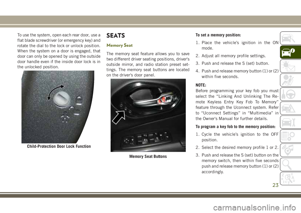
The memory seat feature allows you to save
two different driver seating positions, driver's
outside mirror, and radio station preset set-
tings. The memory seat buttons are located
on the driver's door panel.To set a memory position:
1. Place the vehicle’s ignition in the ON
mode.
2. Adjust all memory profile settings.
3. Push and release the S (set) button.
4. Push and release memory button (1) or (2) within five seconds.
NOTE:
Before programming your key fob you must
select the “Linking And Unlinking The Re-
mote Keyless Entry Key Fob To Memory”
feature through the Uconnect system. Refer
to “Uconnect Settings” in “Multimedia” in
the Owner's Manual for further details.
To program a key fob to the memory position:
1. Cycle the vehicle’s ignition to the OFF position.
2. Select the desired memory profile 1 or 2.
3. Push and release the S (set) button on the memory switch, then within five seconds
push and release memory button (1) or (2)
accordingly.
Child-Protection Door Lock Function
Memory Seat Buttons
23
Page 31 of 312
operate for an average of 80 minutes or more
before automatically shutting off. This time
may vary depending on environmental tem-
peratures. The heated steering wheel can
shut off early or may not turn on when the
steering wheel is already warm.
The heated steering wheel control button is
located within the Uconnect system. You can
gain access to the control button through the
climate screen or the controls screen.
• Press the heated steering wheel button
once to turn the heating element on.
• Press the heated steering wheel button
a second time to turn the heating element
off.
NOTE:
The engine must be running for the heated
steering wheel to operate.
Vehicles With Remote Start — If Equipped
On models that are equipped with remote
start, the heated steering wheel can be pro-
grammed to come on during a remote start
through the Uconnect system. Refer to
“Uconnect Settings” in “Multimedia” in the
Owner’s Manual for further information.
WARNING!
•Persons who are unable to feel pain to the
skin because of advanced age, chronic
illness, diabetes, spinal cord injury, medi-
cation, alcohol use, exhaustion, or other
physical conditions must exercise care
when using the steering wheel heater. It
may cause burns even at low tempera-
tures, especially if used for long periods.
• Do not place anything on the steering wheel that insulates against heat, such
as a blanket or steering wheel covers of
any type and material. This may cause
the steering wheel heater to overheat.
MIRRORS
Power Folding Mirrors — If Equipped
If equipped, the switch for the power folding
mirrors is located between the power mirror
switches L (left) and R (right). Push the
switch once and the mirrors will fold in.
Pushing the switch a second time will return
the mirrors to the normal driving position. NOTE:
If the vehicle speed is greater than 10 mph
(16 km/h), the folding feature will be dis-
abled.
If the mirrors are in the folded position, and
the vehicle speed is equal or greater than 10
mph (16 km/h), they will automatically un-
fold.
Resetting The Power Folding Outside Mirrors
To reset the power folding mirrors: Fold and
unfold them by pushing the button (this may
require multiple button pushes). This resets
them to their normal position.
Heated Mirrors — If Equipped
These mirrors are heated to melt
frost or ice. This feature will be ac-
tivated whenever you turn on the
rear window defroster. Refer to “Climate Con-
trols” in this chapter for further information.
29
Page 45 of 312
NOTE:
• It is not necessary to move the temperaturesettings for cold or hot vehicles. The system
automatically adjusts the temperature,
mode, and blower speed to provide comfort
as quickly as possible.
• The temperature can be displayed in U.S. or Metric units by selecting the US/Metric
customer-programmable feature. Refer to
the “Uconnect Settings” in “Multimedia”
in your Owner’s Manual for further
information.
To provide you with maximum comfort in the
Automatic mode during cold start-ups, the
blower fan will remain on low until the engine
warms up. The blower will increase in speed
and transition into Auto mode.
Manual Operation Override
This system offers a full complement of
manual override features. The AUTO symbol
in the front ATC display will be turned off
when the system is being used in the manual
mode.
Operating Tips
Summer Operation
The engine cooling system must be protected
with a high-quality antifreeze coolant to pro-
vide proper corrosion protection and to pro-
tect against engine overheating. OAT coolant
(conforming to MS.90032) is recommended.
Winter Operation
To ensure the best possible heater and defroster
performance, make sure the engine cooling sys-
tem is functioning properly and the proper
amount, type, and concentration of coolant is
used. Use of the Air Recirculation mode during
Winter months is not recommended, because it
may cause window fogging.
Vacation/Storage
Before you store your vehicle, or keep it out of
service (i.e., vacation) for two weeks or more,
run the air conditioning system at idle for about
five minutes, in fresh air with the blower set-
ting on high. This will ensure adequate system
lubrication to minimize the possibility of com-
pressor damage when the system is started
again.
Window Fogging
Vehicle windows tend to fog on the inside in
mild, rainy, and/or humid weather. To clear
the windows, select Defrost or Mix mode and
increase the front blower speed. Do not use
the Recirculation mode without A/C for long
periods, as fogging may occur.
CAUTION!
Failure to follow these cautions can cause
damage to the heating elements:
•
Use care when washing the inside of the
rear window. Do not use abrasive window
cleaners on the interior surface of the
window. Use a soft cloth and a mild
washing solution, wiping parallel to the
heating elements. Labels can be peeled
off after soaking with warm water.
• Do not use scrapers, sharp instru- ments, or abrasive window cleaners on
the interior surface of the window.
• Keep all objects a safe distance from
the window.
43
Page 47 of 312
• Any impact due to rough road conditionsmay trigger the auto-reverse function unex-
pectedly during auto-closure. If this hap-
pens, pull the switch lightly and hold to
close the window manually.
WARNING!
There is no anti-pinch protection when the
window is almost closed. To avoid personal
injury be sure to clear your arms, hands,
fingers and all objects from the window
path before closing.
Reset Auto-Up
Should the Auto-Up feature stop working, the
window probably needs to be reset. To reset
Auto-Up:
1. Pull the window switch up to close the
window completely and continue to hold
the switch up for an additional two sec-
onds after the window is closed.
2. Push the window switch down firmly to open the window completely and continue
to hold the switch down for an additional
two seconds after the window is fully
open.
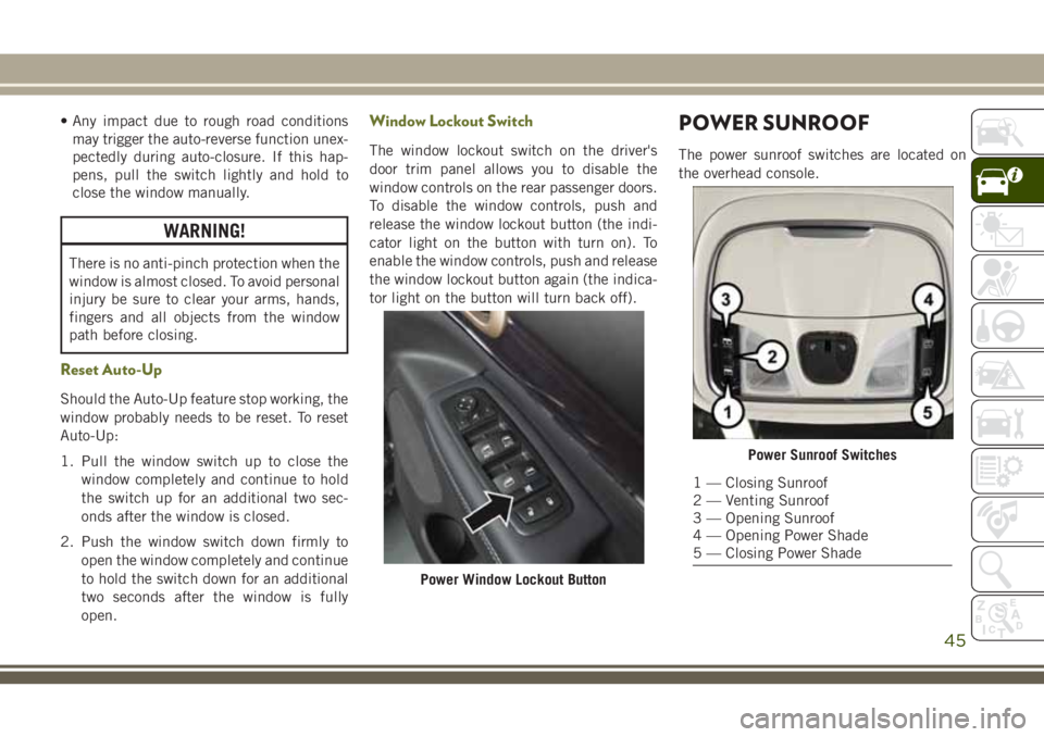
Window Lockout Switch
The window lockout switch on the driver's
door trim panel allows you to disable the
window controls on the rear passenger doors.
To disable the window controls, push and
release the window lockout button (the indi-
cator light on the button with turn on). To
enable the window controls, push and release
the window lockout button again (the indica-
tor light on the button will turn back off).
POWER SUNROOF
The power sunroof switches are located on
the overhead console.
Power Window Lockout Button
Power Sunroof Switches
1 — Closing Sunroof
2 — Venting Sunroof
3 — Opening Sunroof
4 — Opening Power Shade
5 — Closing Power Shade
45
Page 54 of 312
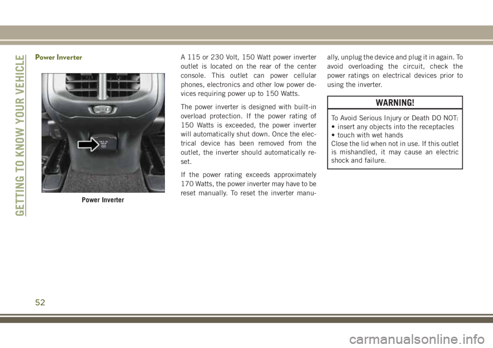
Power InverterA 115 or 230 Volt, 150 Watt power inverter
outlet is located on the rear of the center
console. This outlet can power cellular
phones, electronics and other low power de-
vices requiring power up to 150 Watts.
The power inverter is designed with built-in
overload protection. If the power rating of
150 Watts is exceeded, the power inverter
will automatically shut down. Once the elec-
trical device has been removed from the
outlet, the inverter should automatically re-
set.
If the power rating exceeds approximately
170 Watts, the power inverter may have to be
reset manually. To reset the inverter manu-ally, unplug the device and plug it in again. To
avoid overloading the circuit, check the
power ratings on electrical devices prior to
using the inverter.
WARNING!
To Avoid Serious Injury or Death DO NOT:
• insert any objects into the receptacles
• touch with wet hands
Close the lid when not in use. If this outlet
is mishandled, it may cause an electric
shock and failure.
Power Inverter
GETTING TO KNOW YOUR VEHICLE
52
Page 55 of 312
GETTING TO KNOW YOUR INSTRUMENT PANEL
INSTRUMENT CLUSTER
DISPLAY...................54
Instrument Cluster Display Controls ....54
Oil Change Reset — If Equipped ......55
Instrument Cluster Display Selectable
Items ......................55
WARNING LIGHTS AND
MESSAGES.................56
Red Warning Lights ..............56
Yellow Warning Lights ............59
Yellow Indicator Lights ............63
Green Indicator Lights ............63 White Indicator Lights
............64
Blue Indicator Lights .............65ONBOARD DIAGNOSTIC
SYSTEM—OBDII ............66
Onboard Diagnostic System (OBD II)
Cybersecurity.................66
GETTING TO KNOW YOUR INSTRUMENT PANEL
53
Page 56 of 312
INSTRUMENT CLUSTER
DISPLAY
Your vehicle may be equipped with an instru-
ment cluster display, which offers useful in-
formation to the driver. With the ignition in
the STOP/OFF mode, opening/closing of a
door will activate the display for viewing, and
display the total miles, or kilometers, in the
odometer. Your instrument cluster display is
designed to display important information
about your vehicle’s systems and features.
Using a driver interactive display located on
the instrument panel, your instrument clus-
ter display can show you how systems are
working and give you warnings when they
aren’t. The steering wheel mounted controls
allow you to scroll through and enter the main
menus and submenus. You can access the
specific information you want and make se-
lections and adjustments.
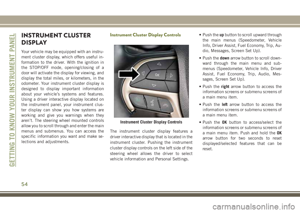
Instrument Cluster Display Controls
The instrument cluster display features a
driver interactive display that is located in the
instrument cluster. Pushing the instrument
cluster display controls on the left side of the
steering wheel allows the driver to select
vehicle information and Personal Settings.• Push the
upbutton to scroll upward through
the main menus (Speedometer, Vehicle
Info, Driver Assist, Fuel Economy, Trip, Au-
dio, Messages, Screen Set Up).
• Push the downarrow button to scroll down-
ward through the main menu and sub-
menus (Speedometer, Vehicle Info, Driver
Assist, Fuel Economy, Trip, Audio, Mes-
sages, Screen Set Up).
• Push the rightarrow button to access the
information screens or submenu screens of
a main menu item.
• Push the leftarrow button to access the
information screens or submenu screens of
a main menu item.
• Push the OKbutton to access/select the
information screens or submenu screens of
a main menu item. Push and hold the OK
arrow button for two seconds to reset
displayed/selected features that can be
reset.
Instrument Cluster Display Controls
GETTING TO KNOW YOUR INSTRUMENT PANEL
54
Page 57 of 312
Oil Change Reset — If Equipped
Your vehicle is equipped with an engine oil
change indicator system. The “Oil Change
Required” message will display in the instru-
ment cluster display for five seconds after a
single chime has sounded to indicate the
next scheduled oil change interval. The en-
gine oil change indicator system is duty cycle
based, which means the engine oil change
interval may fluctuate, dependent upon your
personal driving style.
Unless reset, this message will continue to
display each time you cycle the ignition to the
ON/RUN position. To turn off the message
temporarily, push and release theOKbutton.
To reset the oil change indicator system (after
performing the scheduled maintenance), re-
fer to the following procedure.
Oil Life Reset
1. Without pushing the brake pedal, push and release the ENGINE START/STOP
button and place the ignition to the ON/
RUN position (do not start the engine). 2. Navigate to "Oil Life" submenu in "Vehicle
Info" in the instrument cluster display.
3. Push and hold the OKbutton until the
gauge resets to 100%.
Secondary Method For Oil Change Reset Proce-
dure
1. Without pushing the brake pedal, push and release the ENGINE START/STOP
button and place the ignition to the ON/
RUN position (do not start the engine).
2. Fully press the accelerator pedal, slowly, three times within ten seconds.
3. Without pushing the brake pedal, push and release the ENGINE START/STOP
button once to return the ignition to the
OFF/LOCK position.
NOTE:
If the indicator message illuminates when
you start the vehicle, the oil change indicator
system did not reset. If necessary, repeat this
procedure.
Instrument Cluster Display Selectable
Items
The instrument cluster display can be used to
view the following main menu items:
Speedometer Stop/Start
Vehicle Info Audio
Driver Assist Messages
Fuel Economy Screen Setup
Trip Gear Shift Indicator (GSI)
NOTE:
Depending on the vehicles options, feature
settings may vary. Refer to the “Instrument
Cluster Display” in “Getting To know Your
Instrument Panel” in the Owner’s Manual for
further information.
55
Page 105 of 312
Your vehicle may also be designed to perform
any of these other functions in response to
the Enhanced Accident Response System:
• Turn off the Fuel Filter Heater, Turn off theHVAC Blower Motor, Close the HVAC Circu-
lation Door
• Cut off battery power to the: – Engine
– Electric Motor (if equipped)
– Electric power steering
– Brake booster
– Electric park brake
– Automatic transmission gear selector
– Horn
– Front wiper
– Headlamp washer pump NOTE:
After an accident, remember to cycle the
ignition to the STOP (OFF/LOCK) position
and remove the key from the ignition switch
to avoid draining the battery. Carefully check
the vehicle for fuel leaks in the engine com-
partment and on the ground near the engine
compartment and fuel tank before resetting
the system and starting the engine. If there
are no fuel leaks or damage to the vehicle
electrical devices (e.g. headlights) after an
accident, reset the system by following the
procedure described below.
Enhanced Accident Response System Reset
Procedure
In order to reset the Enhanced Accident Re-
sponse System functions after an event, the
ignition switch must be changed from igni-
tion START or ON/RUN to ignition OFF. Care-
fully check the vehicle for fuel leaks in the
engine compartment and on the ground near
the engine compartment and fuel tank before
resetting the system and starting the engine.
Maintaining Your Air Bag System
WARNING!
•Modifications to any part of the air bag
system could cause it to fail when you
need it. You could be injured if the air bag
system is not there to protect you. Do not
modify the components or wiring, includ-
ing adding any kind of badges or stickers
to the steering wheel hub trim cover or the
upper right side of the instrument panel.
Do not modify the front bumper, vehicle
body structure, or add aftermarket side
steps or running boards.
• It is dangerous to try to repair any part of
the air bag system yourself. Be sure to
tell anyone who works on your vehicle
that it has an air bag system.
• Do not attempt to modify any part of your
air bag system. The air bag may inflate
accidentally or may not function prop-
erly if modifications are made. Take your
vehicle to an authorized dealer for any
air bag system service. If your seat, in-
cluding your trim cover and cushion,
needs to be serviced in any way (includ-
103