torque JEEP CHEROKEE 2018 Owner handbook (in English)
[x] Cancel search | Manufacturer: JEEP, Model Year: 2018, Model line: CHEROKEE, Model: JEEP CHEROKEE 2018Pages: 312, PDF Size: 4.91 MB
Page 65 of 312
— Loose Fuel Filler Cap Warning Light
— If Equipped
This warning light will illuminate when the
fuel filler cap is loose. Properly close the filler
cap to disengage the light. If the light does
not turn off, please see an authorized dealer.
Yellow Indicator Lights
— Glow Plug Light — If Equipped
This vehicle will inhibit engine cranking when
the ambient temperature is less than –22° F
(–30° C) and the oil temperature sensor read-
ing indicates an engine block heater has not
been used. The Glow Plug light will flash
during in cold weather for up to ten seconds.
If equipped with a block heater harness the
message "Plug In Engine Heater", will be
displayed in the instrument cluster when the
ambient temperature is below 5°F (-15° C) at
the time the engine is shut off as a reminder
to avoid possible crank delays at the next cold
start.
— Low Diesel Exhaust Fluid (DEF) Indi-
cator Light — If Equipped
The Low Diesel Exhaust Fluid (DEF) Indicator
will illuminate if the vehicle is low on Diesel
Exhaust Fluid (DEF). Refer to “Starting And
Operating” for further information.
— Forward Collision Warning Off Indi-
cator Light — If Equipped
This light indicates that Forward Collision
Warning is off.
— 4WD Low Indicator Light —
If Equipped
This light alerts the driver that the vehicle is
in the four-wheel drive LOW mode. The front
and rear driveshafts are mechanically locked
together forcing the front and rear wheels to
rotate at the same speed. Low range provides
a greater gear reduction ratio to provide in-
creased torque at the wheels.
Refer to “Four-Wheel Drive Operation — If
Equipped” in “Starting And Operating” for
further information on four-wheel drive op-
eration and proper use.
— NEUTRAL Indicator Light —
If Equipped
This light alerts the driver that the 4WD
power transfer case is in the NEUTRAL mode
and the front and rear driveshafts are disen-
gaged from the powertrain.
— Rear Fog Indicator — If Equipped
This indicator light will illuminate when the
rear fog lights are on.
— Rear Axle Lock Indicator Light
This light indicates when the rear axle lock
has been activated.
Green Indicator Lights
— Adaptive Cruise Control (ACC) Set
With Target Vehicle Light — If Equipped
This will display when the ACC is set and a
target vehicle is detected. Refer to “Adaptive
Cruise Control (ACC)” in “Starting And Oper-
ating” for further information.
63
Page 66 of 312
— Adaptive Cruise Control (ACC) Set
Without Target Vehicle Light — If Equipped
This will display the distance setting for the
ACC system when the system is engaged.
Refer to “Adaptive Cruise Control (ACC)” in
“Starting And Operating” for further informa-
tion.
eco— ECO Mode Indicator Light
This light will turn on when ECO Mode is
active.
— Cruise Control Set Indicator Light
— If Equipped
This light will turn on when the speed control
is set to the desired speed. Refer to “Speed
Control” in “Starting And Operating” for fur-
ther information.
— Front Fog Indicator Light —
If Equipped
This indicator will illuminate when the front
fog lights are on.
— LaneSense Indicator Light —
If Equipped
The LaneSense indicator is solid green when
both lane markings have been detected and
the system is “armed” and ready to provide
visual and torque warnings if an uninten-
tional lane departure occurs. Refer to “Lane-
Sense — If Equipped" in “Starting And Op-
erating” for further information.
— Park/Headlight On Indicator Light
This indicator light will illuminate when the
park lights or headlights are turned on.
— Stop/Start Active Indicator Light —
If Equipped
This indicator light will illuminate when the
Stop/Start function is in “Autostop” mode.
— Turn Signal Indicator Lights
When the left or right turn signal is activated,
the turn signal indicator will flash indepen-
dently and the corresponding exterior turn
signal lamps will flash. Turn signals can be
activated when the multifunction lever is
moved down (left) or up (right). NOTE:
• A continuous chime will sound if the ve-
hicle is driven more than 1 mile (1.6 km)
with either turn signal on.
• Check for an inoperative outside light bulb if either indicator flashes at a rapid rate.
White Indicator Lights
— Adaptive Cruise Control (ACC)
Ready Light — If Equipped
This light will turn on when Adaptive Cruise
Control (ACC) has been turned on, but is not
set. Refer to “Adaptive Cruise Control (ACC)”
in “Starting And Operating” for further infor-
mation.
— Adaptive Cruise Control (ACC) Set
Light — If Equipped
This light will turn on when the vehicle
equipped with Adaptive Cruise Control (ACC)
has reached the speed desired and the set
button has been selected. Refer to “Adaptive
Cruise Control” in “Starting And Operating”
for further information.
GETTING TO KNOW YOUR INSTRUMENT PANEL
64
Page 71 of 312
required. However, the conventional brake
system will continue to operate normally if
the “Anti-Lock Brake Warning Light” is on.
If the “Anti-Lock Brake Warning Light” is on,
the brake system should be serviced as soon
as possible to restore the benefits of anti-lock
brakes. If the “Anti-Lock Brake Warning
Light” does not come on when the ignition is
turned to the ON/RUN mode, have the light
repaired as soon as possible.
Electronic Brake Control System
Your vehicle is equipped with an advanced
Electronic Brake Control system (EBC). This
system includes Electronic Brake Force Dis-
tribution (EBD), Anti-Lock Brake System
(ABS), Brake Assist System (BAS), Hill Start
Assist (HSA), Traction Control System (TCS),
Electronic Stability Control (ESC), and Elec-
tronic Roll Mitigation (ERM). These systems
work together to enhance both vehicle stabil-
ity and control in various driving conditions.
Your vehicle may also be equipped with Trailer
Sway Control (TSC), Ready Alert Braking
(RAB), Rain Brake Support (RBS), Dynamic
Steering Torque (DST), Hill Descent Control
(HDC), and Selec-Speed Control (SSC).
Electronic Brake Force Distribution (EBD)
This function manages the distribution of the
braking torque between the front and rear
axles by limiting braking pressure to the rear
axle. This is done to prevent overslip of the
rear wheels to avoid vehicle instability, and to
prevent the rear axle from entering ABS be-
fore the front axle.
Brake System Warning Light
The red “Brake System Warning Light” will
turn on when the ignition is turned to the
ON/RUN mode and may stay on for as long as
four seconds.
If the “Brake System Warning Light” remains
on or comes on while driving, it indicates that
the brake system is not functioning properly
and that immediate service is required. If the“Brake System Warning Light” does not
come on when the ignition is turned to the
ON/RUN mode, have the light repaired as
soon as possible.
Brake Assist System (BAS)
The BAS is designed to optimize the vehicle’s
braking capability during emergency braking
maneuvers. The system detects an emer-
gency braking situation by sensing the rate
and amount of brake application and then
applies optimum pressure to the brakes. This
can help reduce braking distances. The BAS
complements the anti-lock brake system
(ABS). Applying the brakes very quickly re-
sults in the best BAS assistance. To receive
the benefit of the system, you must apply
continuous braking pressure during the stop-
ping sequence, (do not “pump” the brakes).
Do not reduce brake pedal pressure unless
braking is no longer desired. Once the brake
pedal is released, the BAS is deactivated.
69
Page 73 of 312
For vehicles not equipped with an instrument
cluster display, perform the following steps:
1. Center the steering wheel (front wheelspointing straight forward).
2. Shift the transmission into PARK.
3. Apply the parking brake.
4. Start the engine.
5. Rotate the steering wheel slightly more than one-half turn to the left.
6. Push the “ESC Off” button located in the lower switch bank below the climate con-
trol four times within 20 seconds. The
“ESC Off Indicator Light” should turn on
and turn off two times.
7. Rotate the steering wheel back to center and then an additional slightly more than
one-half turn to the right.
8. Turn the ignition to the OFF mode and then back to ON. If the sequence was
completed properly, the “ESC Off Indica-
tor Light” will blink several times to con-
firm HSA is disabled.
9. Repeat these steps if you want to return this feature to its previous setting.Towing With HSA
HSA will also provide assistance to mitigate
roll back while towing a trailer.
WARNING!
• If you use a trailer brake controller withyour trailer, the trailer brakes may be
activated and deactivated with the brake
switch. If so, there may not be enough
brake pressure to hold both the vehicle
and the trailer on a hill when the brake
pedal is released. In order to avoid roll-
ing down an incline while resuming ac-
celeration, manually activate the trailer
brake or apply more vehicle brake pres-
sure prior to releasing the brake pedal.
• HSA is not a parking brake. Always apply
the parking brake fully when exiting your
vehicle. Also, be certain to place the
transmission in PARK.
• Failure to follow these warnings can re-
sult in a collision or serious personal
injury.
Traction Control System (TCS)
This system monitors the amount of wheel
spin of each of the driven wheels. If wheel
spin is detected, the TCS may apply brake
pressure to the spinning wheel(s) and/or re-
duce engine power to provide enhanced ac-
celeration and stability. A feature of the TCS,
Brake Limited Differential (BLD), functions
similar to a limited slip differential and con-
trols the wheel spin across a driven axle. If
one wheel on a driven axle is spinning faster
than the other, the system will apply the
brake of the spinning wheel. This will allow
more engine torque to be applied to the wheel
that is not spinning. BLD may remain en-
abled even if TCS and ESC are in a reduced
mode.
Electronic Stability Control (ESC)
This system enhances directional control and
stability of the vehicle under various driving
conditions. ESC corrects for oversteering or
understeering of the vehicle by applying the
brake of the appropriate wheel(s) to assist in
counteracting the oversteer or understeer
condition. Engine power may also be reduced
to help the vehicle maintain the desired path.
71
Page 75 of 312
should be used for most driving conditions.
Alternate ESC modes should only be used for
specific reasons as noted in the following
paragraphs.
Partial Off
The “Partial Off” mode is intended for times
when a more spirited driving experience is
desired. This mode may modify TCS and ESC
thresholds for activation, which allows for
more wheel spin than normally allowed. This
mode may be useful if the vehicle becomes
stuck.
To enter the “Partial Off” mode, momentarily
push the “ESC Off” switch and the “ESC Off
Indicator Light” will illuminate. To turn the
ESC on again, momentarily push the “ESC
Off” switch and the “ESC Off Indicator Light”
will turn off.
NOTE:
For vehicles with multiple partial ESC modes
a momentary button push will toggle the ESC
mode. Multiple momentary button pushed
may be required to return to ESC On.WARNING!
• When in “Partial Off” mode, the TCSfunctionality of ESC, (except for the lim-
ited slip feature described in the TCS
section), has been disabled and the
“ESC Off Indicator Light” will be illumi-
nated. When in “Partial Off” mode, the
engine power reduction feature of TCS is
disabled, and the enhanced vehicle sta-
bility offered by the ESC system is re-
duced.
• Trailer Sway control (TSC) is disabled
when the ESC system is in the “Partial
Off” mode.
Full Off — If Equipped
This mode is intended for off-highway or
off-road use only and should not be used on
any public roadways. In this mode, TCS and
ESC features are turned OFF. To enter the
“Full Off” mode, push and hold the “ESC
Off” switch for five seconds while the vehicle
is stopped with the engine running. After five
seconds, a chime will sound, the “ESC Off
Indicator Light” will illuminate, and the “ESC OFF” message will display in the in-
strument cluster. To turn ESC ON again,
momentarily push the “ESC Off” switch.
NOTE:
System may switch from ESC “Full Off” to
“Partial Off” mode when vehicle exceeds a
predetermined speed. When the vehicle
speed slows below the predetermined speed
the system will return to ESC “Full Off”.
ESC modes may also be affected by drive
modes if so equipped.
WARNING!
• In the ESC “Full Off” mode, the engine
torque reduction and stability features
are disabled. Therefore, enhanced ve-
hicle stability offered by the ESC system
is unavailable. In an emergency evasive
maneuver, the ESC system will not en-
gage to assist in maintaining stability.
ESC “Full Off” mode is intended for
off-highway or off-road use only.
• With the ESC switched off, the en-
hanced vehicle stability offered by ESC
is unavailable. In an emergency evasive
73
Page 78 of 312
Dynamic Steering Torque (DST)
Dynamic Steering Torque is a feature of the
ESC and Electric Power Steering (EPS) mod-
ules that provides torque at the steering
wheel for certain driving conditions in which
the ESC module is detecting vehicle instabil-
ity. The torque that the steering wheel re-
ceives is only meant to help the driver realize
optimal steering behavior in order to reach/
maintain vehicle stability. The only notifica-
tion the driver receives that the feature is
active is the torque applied to the steering
wheel.
NOTE:
The DST feature is only meant to help the
driver realize the correct course of action
through small torques on the steering wheel,
which means the effectiveness of the DST
feature is highly dependent on the driver’s
sensitivity and overall reaction to the applied
torque. It is very important to realize that this
feature will not steer the vehicle, meaning
the driver is still responsible for steering the
vehicle.
Hill Descent Control (HDC) — If Equipped
HDC is intended for low speed off road driv-
ing while in 4WD Low Range. HDC maintains
vehicle speed while descending hills during
various driving situations. HDC controls ve-
hicle speed by actively controlling the brakes.
HDC Has Three States:
1. Off (feature is not enabled and will notactivate).
2. Enabled (feature is enabled and ready but activation conditions are not met, or
driver is actively overriding with brake or
throttle application).
3. Active (feature is enabled and actively controlling vehicle speed).
Enabling HDC
HDC is enabled by pushing the HDC switch,
but the following conditions must also be met
to enable HDC:
• Driveline is in 4WD Low Range.
• Vehicle speed is below 5 mph (8 km/h).
• Parking brake is released.
• Driver door is closed. Activating HDC
Once HDC is enabled it will activate auto-
matically if driven down a grade of sufficient
magnitude. The set speed for HDC is select-
able by the driver, and can be adjusted by
using the gear shift +/-. The following sum-
marizes the HDC set speeds:
HDC Target Set Speeds
• P = No set speed. HDC may be enabled but
will not activate.
• R = 0.6 mph (1 km/h)
• N = 1.2 mph (2 km/h)
• D = 0.6 mph (1 km/h)
• 1st = 0.6 mph (1 km/h)
• 2nd = 1.2 mph (2 km/h)
• 3rd = 1.8 mph (3 km/h)
• 4th = 2.5 mph (4 km/h)
• 5th = 3.1 mph (5 km/h)
• 6th = 3.7 mph (6 km/h)
• 7th = 4.3 mph (7 km/h)
• 8th = 5.0 mph (8 km/h)
• 9th = 5.6 mph (9 km/h) – If Equipped
SAFETY
76
Page 79 of 312
NOTE:
During HDC the +/- shifter input is used for
HDC target speed selection, but will not af-
fect the gear chosen by the transmission.
When actively controlling HDC the transmis-
sion will shift appropriately for the driver-
selected set speed and corresponding driving
conditions.
Driver Override
The driver may override HDC activation with
throttle or brake application at anytime.
Deactivating HDC
HDC will be deactivated but remain available
if any of the following conditions occur:
• Driver overrides HDC set speed with throttleor brake application.
• Vehicle speed exceeds 20 mph (32 km/h) but remains below 40 mph (64 km/h).
• Vehicle is on a downhill grade of insuffi- cient magnitude, is on level ground, or is on
an uphill grade.
• Vehicle is shifted to park. Disabling HDC
HDC will be deactivated and disabled if any
of the following conditions occur:
• The driver pushes the HDC switch.
• The driveline is shifted out of 4WD Low
Range.
• The parking brake is applied.
• Driver door opens.
• The vehicle is driven greater than 20 mph (32 km/h) for greater than 70 seconds.
• The vehicle is driven greater than 40 mph (64 km/h) (HDC exits immediately).
• HDC detects excessive brake temperature.
Feedback To The Driver
The instrument cluster has an HDC icon and
the HDC switch has an LED icon, which offers
feedback to the driver about the state HDC is
in.
• The cluster icon and switch lamp will illu- minate and remain on solid when HDC is
enabled or activated. This is the normal
operating condition for HDC. • The cluster icon and switch lamp will flash
for several seconds then extinguish when
the driver pushes the HDC switch but en-
able conditions are not met.
• The cluster icon and switch lamp will flash for several seconds then extinguish when
HDC disables due to excess speed.
• The cluster icon and switch lamp will flash when HDC deactivates due to overheated
brakes. The flashing will stop and HDC will
activate again once the brakes have cooled
sufficiently.
WARNING!
HDC is only intended to assist the driver in
controlling vehicle speed when descend-
ing hills. The driver must remain attentive
to the driving conditions and is responsible
for maintaining a safe vehicle speed.
Selec Speed Control (SSC) — If Equipped
SSC is intended for off road driving in 4WD
Low Range only. SSC maintains vehicle
speed by actively controlling engine torque
and brakes.
77
Page 133 of 312
Additionally, on dry pavement under heavy
throttle input (where one may have no wheel
spin), torque will be sent to the rear in a
pre-emptive effort to improve vehicle launch
and performance characteristics.
CAUTION!
All wheels must have the same size and type
tires. Unequal tire sizes must not be used.
Unequal tire size may cause failure of the
power transfer unit.
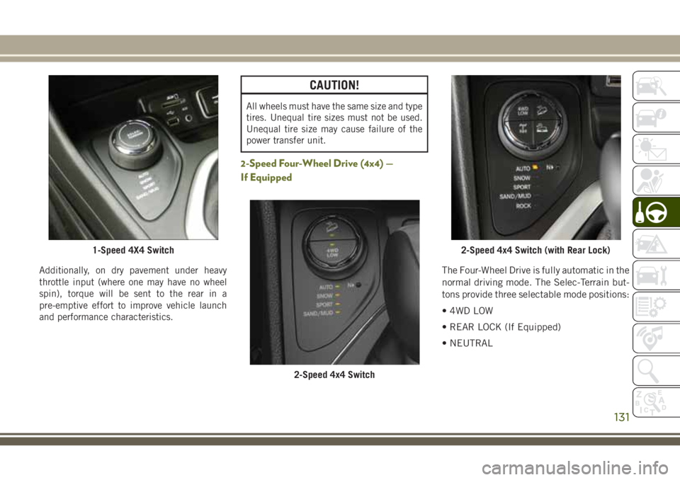
2-Speed Four-Wheel Drive (4x4) —
If Equipped
The Four-Wheel Drive is fully automatic in the
normal driving mode. The Selec-Terrain but-
tons provide three selectable mode positions:
• 4WD LOW
• REAR LOCK (If Equipped)
• NEUTRAL
1-Speed 4X4 Switch
2-Speed 4x4 Switch
2-Speed 4x4 Switch (with Rear Lock)
131
Page 134 of 312
When additional traction is required, the
4WD LOW range position can be used to
provide an additional gear reduction which
allows for increased torque to be delivered to
both the front and rear wheels. 4WD LOW is
intended for loose, slippery road surfaces
only. Driving in 4WD LOW on dry, hard-
surfaced roads may cause increased tire wear
and damage to driveline components.
When operating your vehicle in 4WD LOW,
the engine speed is approximately three
times that of the normal driving mode at a
given road speed. Take care not to overspeed
the engine and do not exceed 25 mph
(40 km/h).
Proper operation of four-wheel drive vehicles
depends on tires of equal size, type, and
circumference on each wheel. Any difference
will adversely affect shifting and cause dam-
age to the driveline components.
Because four-wheel drive provides improved
traction, there is a tendency to exceed safe
turning and stopping speeds. Do not go faster
than road conditions permit.Shift Positions
For additional information on the appropriate
use of each 4WD system mode position, see
the information below:
NEUTRAL
This range disengages the driveline from the
powertrain.
WARNING!
You or others could be injured or killed if
you leave the vehicle unattended with the
power transfer unit in the NEUTRAL (N)
position without first fully engaging the
parking brake. The NEUTRAL (N) position
disengages both the front and rear drive-
shafts from the powertrain and will allow
the vehicle to roll, even if the automatic
transmission is in PARK (or manual trans-
mission is in gear). The parking brake
should always be applied when the driver
is not in the vehicle.
4WD LOW
This range is for low speed four-wheel drive.
It provides an additional gear reduction
which allows for increased torque to be deliv-
ered to both the front and rear wheels while
providing maximum pulling power for loose,
slippery road surfaces only. Do not exceed
25 mph (40 km/h).
NOTE:
Refer to “Selec-Terrain — If Equipped” for
further information on the various positions
and their intended usages.
Shifting Procedures
Shifting Into 4X4 LOW
With the vehicle at speeds of 0 to 3 mph (0 to
5 km/h), the ignition in the ON mode and the
engine running, shift the transmission into
NEUTRAL, and push the “4WD LOW” button
once. The “4WD LOW” indicator light in the
instrument cluster will begin to flash and
remain on solid when the shift is complete.
STARTING AND OPERATING
132
Page 154 of 312
When both lane markings are detected and
the driver unintentionally drifts out of the
lane (no turn signal applied), the LaneSense
system provides a haptic warning in the form
of torque applied to the steering wheel, as
well as a visual warning in the instrument
cluster display, to prompt the driver to remain
within the lane boundaries.
The driver may manually override the haptic
warning by applying torque into the steering
wheel at any time.
When only a single lane marking is detected
and the driver unintentionally drifts across the
lane marking (no turn signal applied), the
LaneSense system provides a visual warning
through the instrument cluster display to
prompt the driver to remain within the lane.
When only a single lane marking is detected, a
haptic (torque) warning will not be provided.
NOTE:
When operating conditions have been met,
the LaneSense system will monitor if thedriver’s hands are on the steering wheel and
provide an audible and visual warning to the
driver when the driver’s hands are not de-
tected on the steering wheel. The system will
cancel if the driver does not return their
hands to the wheel.
Turning LaneSense On Or Off
The default status of LaneSense is “off”.
The LaneSense button is located on the
switch panel below the Uconnect display.
To turn the LaneSense system on, push the
LaneSense button (LED turns off). A “Lane-
Sense On” message is shown in the instru-
ment cluster display.
To turn the LaneSense system off, push the
LaneSense button once (LED turns on).
NOTE:
The LaneSense system will retain the last
system state, on or off, from the last ignition
cycle when the ignition is changed to the
ON/RUN position.
LaneSense Warning Message
The LaneSense system will indicate the cur-
rent lane drift condition through the instru-
ment cluster display.
Base Instrument Cluster Display — If Equipped
When the LaneSense system is on; the lane
lines are gray when both of the lane bound-
aries have not been detected and the Lane-
Sense telltale is solid white.
Left Lane Departure — Only Left Lane Detected
• When the LaneSense system is on, the
LaneSense telltale is solid white when only
the left lane marking has been detected
and the system is ready to provide visual
warnings in the instrument cluster display
if an unintentional lane departure occurs.
• When the LaneSense system senses the lane has been approached and is in a lane
departure situation, the left thick lane line
flashes from white to gray, the left thin line
remains solid white and the LaneSense
telltale changes from solid white to flashing
yellow.
STARTING AND OPERATING
152