torque JEEP CHEROKEE 2019 Owner handbook (in English)
[x] Cancel search | Manufacturer: JEEP, Model Year: 2019, Model line: CHEROKEE, Model: JEEP CHEROKEE 2019Pages: 344, PDF Size: 6.35 MB
Page 153 of 344
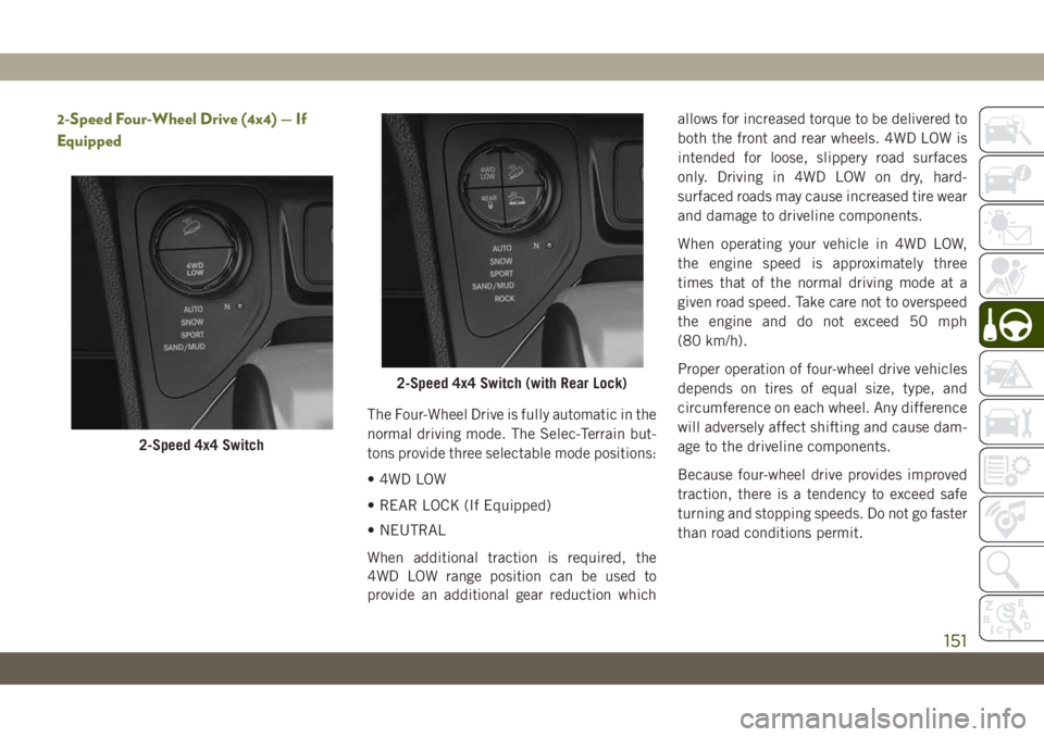
2-Speed Four-Wheel Drive (4x4) — If
Equipped
The Four-Wheel Drive is fully automatic in the
normal driving mode. The Selec-Terrain but-
tons provide three selectable mode positions:
• 4WD LOW
• REAR LOCK (If Equipped)
• NEUTRAL
When additional traction is required, the
4WD LOW range position can be used to
provide an additional gear reduction whichallows for increased torque to be delivered to
both the front and rear wheels. 4WD LOW is
intended for loose, slippery road surfaces
only. Driving in 4WD LOW on dry, hard-
surfaced roads may cause increased tire wear
and damage to driveline components.
When operating your vehicle in 4WD LOW,
the engine speed is approximately three
times that of the normal driving mode at a
given road speed. Take care not to overspeed
the engine and do not exceed 50 mph
(80 km/h).
Proper operation of four-wheel drive vehicles
depends on tires of equal size, type, and
circumference on each wheel. Any difference
will adversely affect shifting and cause dam-
age to the driveline components.
Because four-wheel drive provides improved
traction, there is a tendency to exceed safe
turning and stopping speeds. Do not go faster
than road conditions permit.
2-Speed 4x4 Switch
2-Speed 4x4 Switch (with Rear Lock)
151
Page 154 of 344
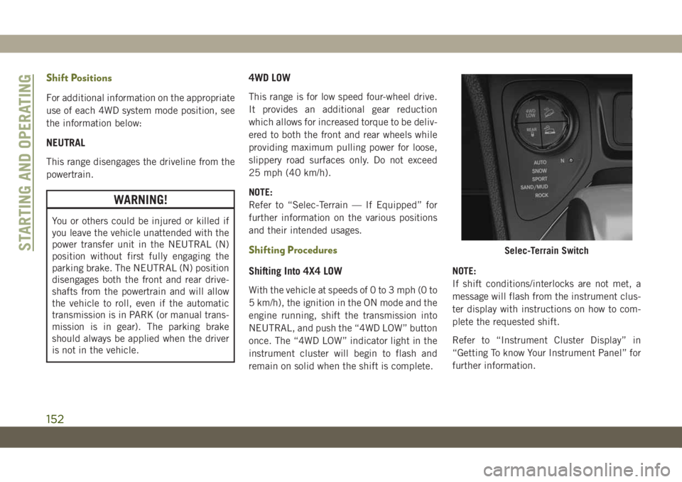
Shift Positions
For additional information on the appropriate
use of each 4WD system mode position, see
the information below:
NEUTRAL
This range disengages the driveline from the
powertrain.
WARNING!
You or others could be injured or killed if
you leave the vehicle unattended with the
power transfer unit in the NEUTRAL (N)
position without first fully engaging the
parking brake. The NEUTRAL (N) position
disengages both the front and rear drive-
shafts from the powertrain and will allow
the vehicle to roll, even if the automatic
transmission is in PARK (or manual trans-
mission is in gear). The parking brake
should always be applied when the driver
is not in the vehicle.
4WD LOW
This range is for low speed four-wheel drive.
It provides an additional gear reduction
which allows for increased torque to be deliv-
ered to both the front and rear wheels while
providing maximum pulling power for loose,
slippery road surfaces only. Do not exceed
25 mph (40 km/h).
NOTE:
Refer to “Selec-Terrain — If Equipped” for
further information on the various positions
and their intended usages.
Shifting Procedures
Shifting Into 4X4 LOW
With the vehicle at speeds of 0 to 3 mph (0 to
5 km/h), the ignition in the ON mode and the
engine running, shift the transmission into
NEUTRAL, and push the “4WD LOW” button
once. The “4WD LOW” indicator light in the
instrument cluster will begin to flash and
remain on solid when the shift is complete.NOTE:
If shift conditions/interlocks are not met, a
message will flash from the instrument clus-
ter display with instructions on how to com-
plete the requested shift.
Refer to “Instrument Cluster Display” in
“Getting To know Your Instrument Panel” for
further information.
Selec-Terrain SwitchSTARTING AND OPERATING
152
Page 172 of 344
• New vehicles from the dealer must have at
least 30 miles (48 km) accumulated before
the ParkSense Active Park Assist system is
fully calibrated and performs accurately.
This is due to the system’s dynamic vehicle
calibration to improve the performance of
the feature. The system will also continu-
ously perform the dynamic vehicle calibra-
tion to account for differences such as over
or under inflated tires and new tires.
The ParkSense Active Park Assist system can
be enabled and disabled with the ParkSense
Active Park Assist switch, located on the
switch panel below the Uconnect display.
To enable the ParkSense Active
Park Assist system, push the
ParkSense Active Park Assist
switch once (LED turns on).
To disable the ParkSense Active Park Assist
system, push the ParkSense Active Park As-
sist switch again (LED turns off).
Refer to your Owner’s Manual for further
information.LANESENSE
LaneSense Operation
The LaneSense system is operational at
speeds above 37 mph (60 km/h) and below
112 mph (180 km/h). The LaneSense system
uses a forward looking camera to detect lane
markings and measure vehicle position
within the lane boundaries.
When both lane markings are detected and
the driver unintentionally drifts out of the
lane (no turn signal applied), the LaneSense
system provides a haptic warning in the form
of torque applied to the steering wheel, as
well as a visual warning in the instrument
cluster display, to prompt the driver to remain
within the lane boundaries.
The driver may manually override the haptic
warning by applying torque into the steering
wheel at any time.
When only a single lane marking is detected
and the driver unintentionally drifts across
the lane marking (no turn signal applied), theLaneSense system provides a visual warning
through the instrument cluster display to
prompt the driver to remain within the lane.
NOTE:
When operating conditions have been met,
the LaneSense system will monitor if the
driver’s hands are on the steering wheel and
provide an audible and visual warning to the
driver when the driver’s hands are not de-
tected on the steering wheel. The system will
cancel if the driver does not return their
hands to the wheel.
Turning LaneSense On Or Off
The default status of LaneSense is “off”.
The LaneSense button is located on the
switch panel below the Uconnect display.
To turn the LaneSense system
on, push the LaneSense button
(LED turns off). A “LaneSense
On” message is shown in the
instrument cluster display.
To turn the LaneSense system off, push the
LaneSense button once (LED turns on).
STARTING AND OPERATING
170
Page 173 of 344
NOTE:
The LaneSense system will retain the last
system state, on or off, from the last ignition
cycle when the ignition is changed to the
ON/RUN position.
LaneSense Warning Message
The LaneSense system will indicate the cur-
rent lane drift condition through the instru-
ment cluster display.
Base Instrument Cluster Display — If Equipped
When the LaneSense system is on; the lane
lines are gray when both of the lane bound-
aries have not been detected and the Lane-
Sense telltale is solid white.
Left Lane Departure — Only Left Lane Detected
• When the LaneSense system is on, the
LaneSense telltale is solid white when only
the left lane marking has been detected
and the system is ready to provide visual
and haptic warnings in the instrument clus-
ter display if an unintentional lane depar-
ture occurs.• When the LaneSense system senses the
lane has been approached and is in a lane
departure situation, the LaneSense system
will show a solid white left line, a solid gray
right line, and a solid yellow telltale.
NOTE:
The LaneSense system operates with the
similar behavior for a right lane departure
when only the right lane marking has been
detected.
Left Lane Departure — Both Lanes Detected
• When the LaneSense system is on, the lane
lines turn from gray to white to indicate that
both of the lane markings have been de-
tected. The LaneSense telltale is solid
green when both lane markings have been
detected and the system is “armed” to
provide visual warnings in the instrument
cluster display and a torque warning in the
steering wheel if an unintentional lane de-
parture occurs.• When the LaneSense system senses a lane
drift situation, the left thick lane line and
the left thin line turn solid white. The Lane-
Sense telltale changes from solid green to
solid yellow. At this time torque is applied
to the steering wheel in the opposite direc-
tion of the lane boundary.
For example: If approaching the left side of
the lane the steering wheel will turn to the
right.
• When the LaneSense system senses the
lane has been approached and is in a lane
departure situation, the left thick lane line
flashes from white to gray, the left thin line
remains solid white and the LaneSense
telltale changes from solid yellow to flash-
ing yellow. At this time torque is applied to
the steering wheel in the opposite direction
of the lane boundary.
For example: If approaching the left side of
the lane the steering wheel will turn to the
right.
NOTE:
The LaneSense system operates with the
similar behavior for a right lane departure.
171
Page 174 of 344
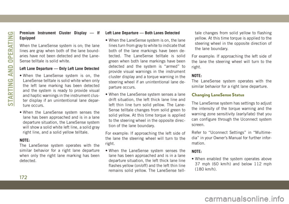
Premium Instrument Cluster Display — If
Equipped
When the LaneSense system is on; the lane
lines are gray when both of the lane bound-
aries have not been detected and the Lane-
Sense telltale is solid white.
Left Lane Departure — Only Left Lane Detected
• When the LaneSense system is on, the
LaneSense telltale is solid white when only
the left lane marking has been detected
and the system is ready to provide visual
and haptic warnings in the instrument clus-
ter display if an unintentional lane depar-
ture occurs.
• When the LaneSense system senses the
lane has been approached and is in a lane
departure situation, the LaneSense system
will show a solid white left line, a solid gray
right line, and a solid yellow telltale.
NOTE:
The LaneSense system operates with the
similar behavior for a right lane departure
when only the right lane marking has been
detected.Left Lane Departure — Both Lanes Detected
• When the LaneSense system is on, the lane
lines turn from gray to white to indicate that
both of the lane markings have been de-
tected. The LaneSense telltale is solid
green when both lane markings have been
detected and the system is “armed” to
provide visual warnings in the instrument
cluster display and a torque warning in the
steering wheel if an unintentional lane de-
parture occurs.
• When the LaneSense system senses a lane
drift situation, the left thick lane line and
left thin line turn solid yellow. The Lane-
Sense telltale changes from solid green to
solid yellow. At this time torque is applied
to the steering wheel in the opposite direc-
tion of the lane boundary.
For example: If approaching the left side of
the lane the steering wheel will turn to the
right.
• When the LaneSense system senses the
lane has been approached and is in a lane
departure situation, the left thick lane line
flashes yellow (on/off) and the left thin line
remains solid yellow. The LaneSense tell-tale changes from solid yellow to flashing
yellow. At this time torque is applied to the
steering wheel in the opposite direction of
the lane boundary.
For example: If approaching the left side of
the lane the steering wheel will turn to the
right.
NOTE:
The LaneSense system operates with the
similar behavior for a right lane departure.
Changing LaneSense Status
The LaneSense system has settings to adjust
the intensity of the torque warning and the
warning zone sensitivity (early/late) that you
can configure through the Uconnect system
screen.
Refer to “Uconnect Settings” in “Multime-
dia” in your Owner’s Manual for further infor-
mation.
NOTE:
• When enabled the system operates above
37 mph (60 km/h) and below 112 mph
(180 km/h).STARTING AND OPERATING
172
Page 175 of 344
• Use of the turn signal suppresses the warn-
ings.
• The system will not apply torque to the
steering wheel whenever a safety system
engages (anti-lock brakes, traction control
system, electronic stability control, forward
collision warning, etc.).
PARKVIEW REAR BACK UP
CAMERA — IF EQUIPPED
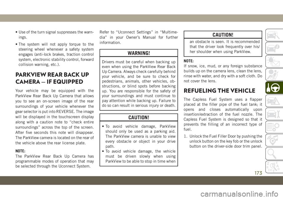
Your vehicle may be equipped with the
ParkView Rear Back Up Camera that allows
you to see an on-screen image of the rear
surroundings of your vehicle whenever the
gear selector is put into REVERSE. The image
will be displayed in the touchscreen display
along with a caution note to “check entire
surroundings” across the top of the screen.
After five seconds this note will disappear.
The ParkView camera is located on the rear of
the vehicle above the rear license plate.
NOTE:
The ParkView Rear Back Up Camera has
programmable modes of operation that may
be selected through the Uconnect System.Refer to “Uconnect Settings” in “Multime-
dia” in your Owner’s Manual for further
information.
WARNING!
Drivers must be careful when backing up
even when using the ParkView Rear Back
Up Camera. Always check carefully behind
your vehicle, and be sure to check for
pedestrians, animals, other vehicles, ob-
structions, or blind spots before backing
up. You are responsible for the safety of
your surroundings and must continue to
pay attention while backing up. Failure to
do so can result in serious injury or death.
CAUTION!
• To avoid vehicle damage, ParkView
should only be used as a parking aid.
The ParkView camera is unable to view
every obstacle or object in your drive
path.
• To avoid vehicle damage, the vehicle
must be driven slowly when using
ParkView to be able to stop in time when
CAUTION!
an obstacle is seen. It is recommended
that the driver look frequently over his/
her shoulder when using ParkView.
NOTE:
If snow, ice, mud, or any foreign substance
builds up on the camera lens, clean the lens,
rinse with water, and dry with a soft cloth. Do
not cover the lens.
REFUELING THE VEHICLE
The Capless Fuel System uses a flapper
placed at the filler pipe of the fuel tank; it
opens and closes automatically upon
insertion/extraction of the fuel nozzle. The
Capless Fuel System is designed so that it
prevents the filling of an incorrect type of
fuel.
1. Unlock the Fuel Filler Door by pushing the
unlock button on the key fob or the unlock
button on the driver-side door trim panel.
173
Page 179 of 344
quantity AdBlue (UREA) is injected into the
exhaust upstream of a catalyst where, when
vaporized, it converts smog-forming nitrogen
oxides (NOx) into harmless nitrogen (N2) and
water vapor (H2O), two natural components
of the air we breathe. You can operate with
the comfort that your vehicle is contributing
to a cleaner, healthier world environment for
this and generations to come.
System Overview
This vehicle is equipped with a AdBlue
(UREA) injection system and a Selective
Catalytic Reduction (SCR) catalyst to meet
the emission requirements.
The AdBlue (UREA) injection system con-
sists of the following components:
• AdBlue (UREA) Tank
• AdBlue (UREA) Pump
• AdBlue (UREA) Injector
• Electronically-heated AdBlue (UREA)
Lines
• NOx sensors• Temperature sensors
• SCR catalyst
The AdBlue (UREA) injection system and
SCR catalyst enable the achievement of die-
sel emissions requirements; while maintain-
ing outstanding fuel economy, drivability,
torque and power ratings.
Refer to “Instrument Cluster Display” in
“Getting To Know Your Instrument Panel” for
system messages and warnings.
NOTE:
• Your vehicle is equipped with a AdBlue
(UREA) injection system. You may occa-
sionally hear an audible clicking noise from
under the vehicle at a stop. This is normal
operation.
• The AdBlue (UREA) pump will run for a
period of time after engine shutdown to
purge the AdBlue (UREA) system. This is
normal operation and may be audible from
the rear of the vehicle.
AdBlue (UREA) Storage
AdBlue (UREA) is considered a very stable
product with a long shelf life. If AdBlue
(UREA) is kept in temperatures between
10° and 90°F (-12° and 32°C), it will last a
minimum of one year.
AdBlue (UREA) is subject to freezing at the
lowest temperatures. For example, AdBlue
(UREA) may freeze at temperatures at or
below 12° F (-11° C). The system has been
designed to operate in this environment.
NOTE:
When working with AdBlue (UREA), it is
important to know that:
• Any containers or parts that come into con-
tact with AdBlue (UREA) must be AdBlue
(UREA) compatible (plastic or stainless
steel). Copper, brass, aluminum, iron or
non-stainless steel should be avoided as
they are subject to corrosion by AdBlue
(UREA).
• If AdBlue (UREA) is spilled, it should be
wiped up completely.
177
Page 201 of 344
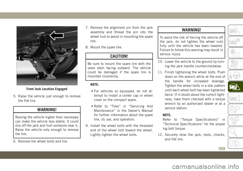
5. Raise the vehicle just enough to remove
the flat tire.
WARNING!
Raising the vehicle higher than necessary
can make the vehicle less stable. It could
slip off the jack and hurt someone near it.
Raise the vehicle only enough to remove
the tire.
6. Remove the wheel bolts and tire.7. Remove the alignment pin from the jack
assembly and thread the pin into the
wheel hub to assist in mounting the spare
tire.
8. Mount the spare tire.
CAUTION!
Be sure to mount the spare tire with the
valve stem facing outward. The vehicle
could be damaged if the spare tire is
mounted incorrectly.
NOTE:
• For vehicles so equipped, do not at-
tempt to install a center cap or wheel
cover on the compact spare.
• Refer to “Tires” in “Servicing And
Maintenance” in the Owner's Manual
for further information about the spare
tire, its use, and operation.
9. Install the wheel bolts with the threaded
end of the wheel bolt toward the wheel.
Lightly tighten the wheel bolts.
WARNING!
To avoid the risk of forcing the vehicle off
the jack, do not tighten the wheel nuts
fully until the vehicle has been lowered.
Failure to follow this warning may result in
serious injury.
10. Lower the vehicle to the ground by turn-
ing the jack handle counterclockwise.
11. Finish tightening the wheel bolts. Push
down on the wrench while at the end of
the handle for increased leverage.
Tighten the wheel bolts in a star pattern
until each wheel bolt has been tightened
twice. If in doubt about the correct tight-
ness, have them checked with a torque
wrench by an authorized dealer or at a
service station.
NOTE:
Refer to “Torque Specifications” in
“Technical Specifications” for the proper
lug bolt torque.
12. Securely stow the jack, tools, chocks,
and flat tire.
Front Jack Location Engaged
199
Page 202 of 344
WARNING!
A loose tire or jack thrown forward in a
collision or hard stop could endanger the
occupants of the vehicle. Always stow the
jack parts and the spare tire in the places
provided. Have the deflated (flat) tire re-
paired or replaced immediately.
Road Tire Installation
1. Mount the road tire on the axle.
2. Install the remaining wheel bolts with the
threaded end of the wheel bolt toward the
wheel. Lightly tighten the wheel bolts.
WARNING!
To avoid the risk of forcing the vehicle off
the jack, do not tighten the wheel nuts
fully until the vehicle has been lowered.
Failure to follow this warning may result in
serious injury.
3. Lower the vehicle to the ground by turning
the jack handle counterclockwise.4. Finish tightening the wheel bolts. Push
down on the wrench while at the end of
the handle for increased leverage. Tighten
the wheel bolts in a star pattern until each
wheel bolt has been tightened twice. If in
doubt about the correct tightness, have
them checked with a torque wrench by an
authorized dealer or service station.
Refer to “Torque Specifications” in
“Technical Specifications” for the proper
lug bolt torque.
5. Lower the jack until it is free. Remove the
wheel chocks. Reassemble the lug wrench
to the jack assembly and stow it in the
spare tire area. Secure the assembly using
the means provided. Release the parking
brake before driving the vehicle.
6. After 25 miles (40 km), check the wheel
bolt torque with a torque wrench to ensure
that all wheel bolts are properly seated
against the wheel.
Declaration Of Conformance
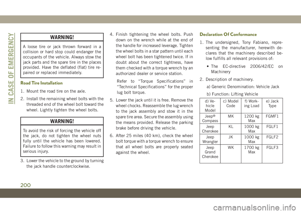
1. The undersigned, Tony Fabiano, repre-
senting the manufacturer, herewith de-
clares that the machinery described be-
low fulfills all relevant provisions of:
• The EC-directive 2006/42/EC on
Machinery
2. Description of machinery.
a) Generic Denomination: Vehicle Jack
b) Function: Lifting Vehicle
d) Ve-
hicle
Modelc) Model
Codef) Work-
ing Loade) Jack
Type
Jeep
®
CompassMK 1200 kg
MaxFGMF1
Jeep
CherokeeKL 1000 kg
MaxFGLF1
Jeep
WranglerJK 1000 kg
MaxFGLF2
Jeep
Grand
CherokeeWK 1700 kg
MaxFGLF3
IN CASE OF EMERGENCY
200
Page 255 of 344
VEHICLE IDENTIFICATION
NUMBER
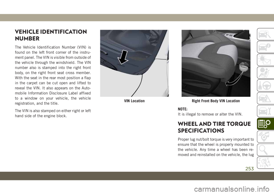
The Vehicle Identification Number (VIN) is
found on the left front corner of the instru-
ment panel. The VIN is visible from outside of
the vehicle through the windshield. The VIN
number also is stamped into the right front
body, on the right front seat cross member.
With the seat in the rear most position a flap
in the carpet can be cut open and lifted to
reveal the VIN. It also appears on the Auto-
mobile Information Disclosure Label affixed
to a window on your vehicle, the vehicle
registration, and the title.
The VIN is also stamped on either right or left
hand side of the engine block.NOTE:
It is illegal to remove or alter the VIN.
WHEEL AND TIRE TORQUE
SPECIFICATIONS
Proper lug nut/bolt torque is very important to
ensure that the wheel is properly mounted to
the vehicle. Any time a wheel has been re-
moved and reinstalled on the vehicle, the lug
VIN LocationRight Front Body VIN Location
253