ECU JEEP CHEROKEE 2019 Owner handbook (in English)
[x] Cancel search | Manufacturer: JEEP, Model Year: 2019, Model line: CHEROKEE, Model: JEEP CHEROKEE 2019Pages: 344, PDF Size: 6.35 MB
Page 185 of 344
Recreational Towing — Front-Wheel Drive
(FWD) Models
DO NOTflat tow this vehicle.
Recreational towing (for front-wheel drive
models) is allowed ONLY if the front wheels
areOFFthe ground. This may be accom-
plished using a tow dolly or vehicle trailer. If
using a tow dolly, follow this procedure:
1. Properly secure the dolly to the tow ve-
hicle, following the dolly manufacturer's
instructions.
2. Drive the front wheels onto the tow dolly.
3. Apply the parking brake. Place automatic
transmission in PARK, or manual trans-
mission in gear. Turn the engine OFF.
4. Properly secure the front wheels to the
dolly, following the dolly manufacturer's
instructions.
5. Turn the ignition to the ON/RUN mode,
but do not start the engine.6. Press and hold the brake pedal.
7. Release the parking brake.
8. Turn the ignition OFF, remove the key fob,
and release the brake pedal.
CAUTION!
• Towing with the front wheels on the
ground will cause severe transmission
damage. Damage from improper towing
is not covered under the New Vehicle
Limited Warranty.
• Ensure that the Electric Park Brake is
released, and remains released, while
being towed.
Recreational Towing — 4x4 Models
Recreational towing is not allowed.
NOTE:
This vehicle may be towed on a flatbed or
vehicle trailer provided all four wheels are
OFF the ground.
CAUTION!
Towing this vehicle withANYof its wheels
on the ground can cause severe transmis-
sion and/or power transfer unit damage.
Damage from improper towing is not cov-
ered under the New Vehicle Limited War-
ranty.
183
Page 192 of 344
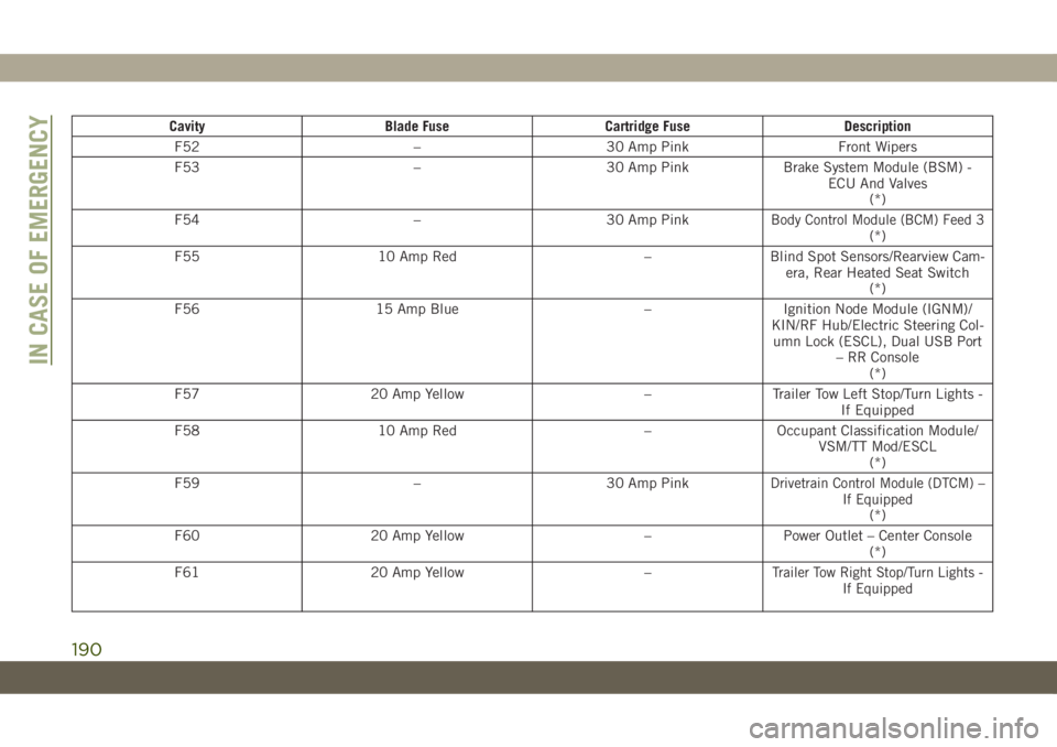
Cavity Blade Fuse Cartridge Fuse Description
F52 – 30 Amp Pink Front Wipers
F53 – 30 Amp Pink Brake System Module (BSM) -
ECU And Valves
(*)
F54 – 30 Amp Pink
Body Control Module (BCM) Feed 3(*)
F55 10 Amp Red – Blind Spot Sensors/Rearview Cam-
era, Rear Heated Seat Switch
(*)
F56 15 Amp Blue – Ignition Node Module (IGNM)/
KIN/RF Hub/Electric Steering Col-
umn Lock (ESCL), Dual USB Port
– RR Console
(*)
F57 20 Amp Yellow – Trailer Tow Left Stop/Turn Lights -
If Equipped
F58 10 Amp Red – Occupant Classification Module/
VSM/TT Mod/ESCL
(*)
F59 – 30 Amp Pink
Drivetrain Control Module (DTCM) –
If Equipped
(*)
F60 20 Amp Yellow – Power Outlet – Center Console
(*)
F61 20 Amp Yellow –
Trailer Tow Right Stop/Turn Lights -
If Equipped
IN CASE OF EMERGENCY
190
Page 194 of 344
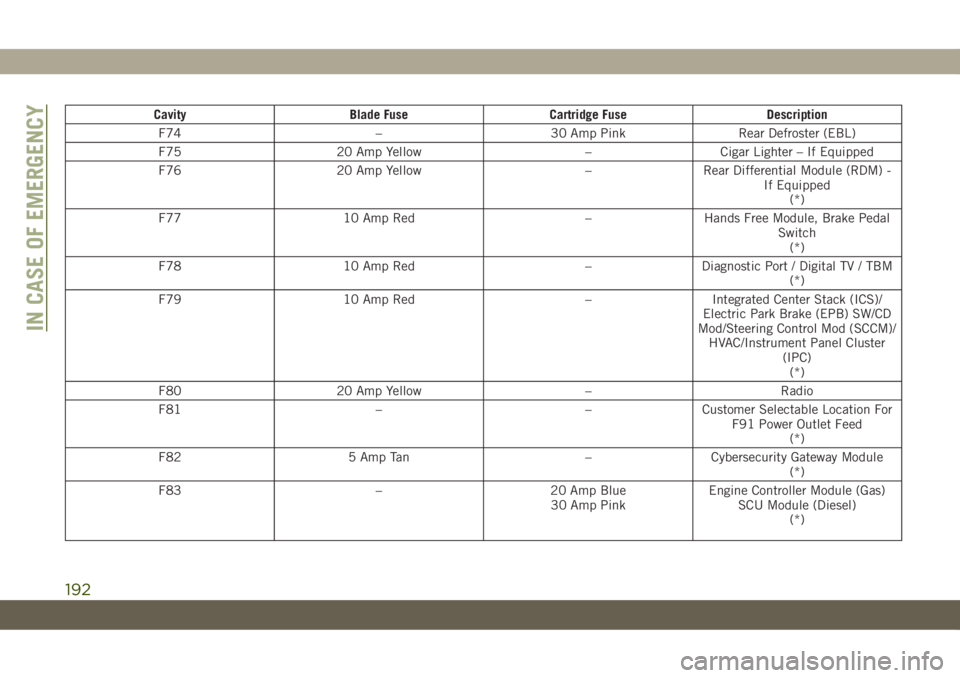
Cavity Blade Fuse Cartridge Fuse Description
F74 – 30 Amp Pink Rear Defroster (EBL)
F75 20 Amp Yellow – Cigar Lighter – If Equipped
F76 20 Amp Yellow – Rear Differential Module (RDM) -
If Equipped
(*)
F77 10 Amp Red – Hands Free Module, Brake Pedal
Switch
(*)
F78 10 Amp Red – Diagnostic Port / Digital TV / TBM
(*)
F79 10 Amp Red – Integrated Center Stack (ICS)/
Electric Park Brake (EPB) SW/CD
Mod/Steering Control Mod (SCCM)/
HVAC/Instrument Panel Cluster
(IPC)
(*)
F80 20 Amp Yellow – Radio
F81 – – Customer Selectable Location For
F91 Power Outlet Feed
(*)
F82 5 Amp Tan – Cybersecurity Gateway Module
(*)
F83 – 20 Amp Blue
30 Amp PinkEngine Controller Module (Gas)
SCU Module (Diesel)
(*)
IN CASE OF EMERGENCY
192
Page 198 of 344
JACKING AND TIRE
CHANGING
WARNING!
• Do not attempt to change a tire on the
side of the vehicle close to moving traf-
fic. Pull far enough off the road to avoid
the danger of being hit when operating
the jack or changing the wheel.
• Being under a jacked-up vehicle is dan-
gerous. The vehicle could slip off the
jack and fall on you. You could be
crushed. Never put any part of your body
under a vehicle that is on a jack. If you
need to get under a raised vehicle, take
it to a service center where it can be
raised on a lift.
• Never start or run the engine while the
vehicle is on a jack.
• The jack is designed to be used as a tool
for changing tires only. The jack should
not be used to lift the vehicle for service
purposes. The vehicle should be jacked
on a firm level surface only. Avoid ice or
slippery areas.
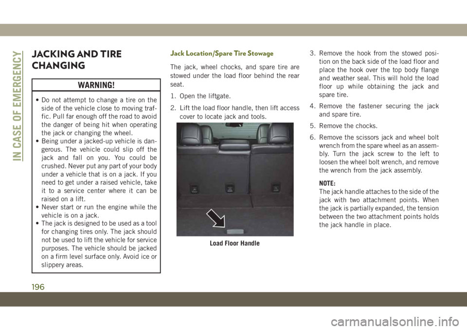
Jack Location/Spare Tire Stowage
The jack, wheel chocks, and spare tire are
stowed under the load floor behind the rear
seat.
1. Open the liftgate.
2. Lift the load floor handle, then lift access
cover to locate jack and tools.3. Remove the hook from the stowed posi-
tion on the back side of the load floor and
place the hook over the top body flange
and weather seal. This will hold the load
floor up while obtaining the jack and
spare tire.
4. Remove the fastener securing the jack
and spare tire.
5. Remove the chocks.
6. Remove the scissors jack and wheel bolt
wrench from the spare wheel as an assem-
bly. Turn the jack screw to the left to
loosen the wheel bolt wrench, and remove
the wrench from the jack assembly.
NOTE:
The jack handle attaches to the side of the
jack with two attachment points. When
the jack is partially expanded, the tension
between the two attachment points holds
the jack handle in place.
Load Floor Handle
IN CASE OF EMERGENCY
196
Page 200 of 344
WARNING!
• If working on or near a roadway, be
extremely careful of motor traffic.
• To assure that spare tires, flat or in-
flated, are securely stowed, spares must
be stowed with the valve stem facing the
ground.
CAUTION!
Do not attempt to raise the vehicle by
jacking on locations other than those indi-
cated in the Jacking Instructions for this
vehicle.
1. Remove the spare tire, jack, wheel
chocks, and wheel bolt wrench.
2. If equipped with aluminum wheels where
the center cap covers the wheel bolts, use
the wheel bolt wrench to pry the center
cap off carefully before raising the
vehicle.
3. Before raising the vehicle, use the wheel
bolt wrench to loosen, but not remove, the
wheel bolts on the wheel with the flat tire.
Turn the wheel bolts counterclockwise
one turn while the wheel is still on the
ground.
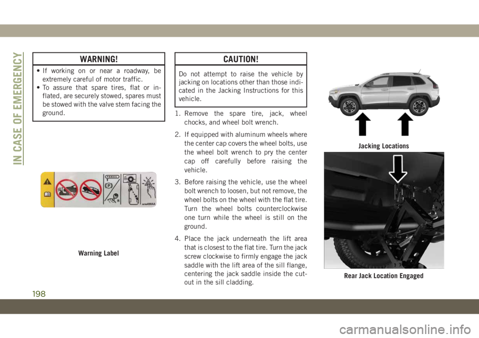
4. Place the jack underneath the lift area
that is closest to the flat tire. Turn the jack
screw clockwise to firmly engage the jack
saddle with the lift area of the sill flange,
centering the jack saddle inside the cut-
out in the sill cladding.
Warning Label
Jacking Locations
Rear Jack Location Engaged
IN CASE OF EMERGENCY
198
Page 201 of 344
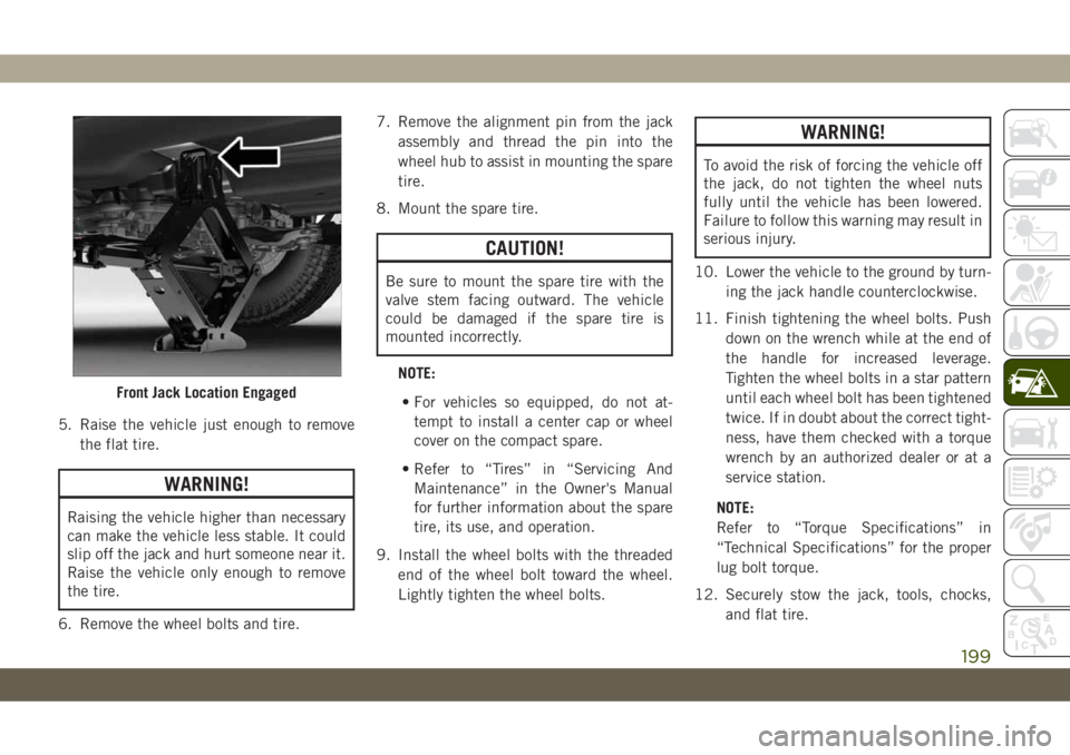
5. Raise the vehicle just enough to remove
the flat tire.
WARNING!
Raising the vehicle higher than necessary
can make the vehicle less stable. It could
slip off the jack and hurt someone near it.
Raise the vehicle only enough to remove
the tire.
6. Remove the wheel bolts and tire.7. Remove the alignment pin from the jack
assembly and thread the pin into the
wheel hub to assist in mounting the spare
tire.
8. Mount the spare tire.
CAUTION!
Be sure to mount the spare tire with the
valve stem facing outward. The vehicle
could be damaged if the spare tire is
mounted incorrectly.
NOTE:
• For vehicles so equipped, do not at-
tempt to install a center cap or wheel
cover on the compact spare.
• Refer to “Tires” in “Servicing And
Maintenance” in the Owner's Manual
for further information about the spare
tire, its use, and operation.
9. Install the wheel bolts with the threaded
end of the wheel bolt toward the wheel.
Lightly tighten the wheel bolts.
WARNING!
To avoid the risk of forcing the vehicle off
the jack, do not tighten the wheel nuts
fully until the vehicle has been lowered.
Failure to follow this warning may result in
serious injury.
10. Lower the vehicle to the ground by turn-
ing the jack handle counterclockwise.
11. Finish tightening the wheel bolts. Push
down on the wrench while at the end of
the handle for increased leverage.
Tighten the wheel bolts in a star pattern
until each wheel bolt has been tightened
twice. If in doubt about the correct tight-
ness, have them checked with a torque
wrench by an authorized dealer or at a
service station.
NOTE:
Refer to “Torque Specifications” in
“Technical Specifications” for the proper
lug bolt torque.
12. Securely stow the jack, tools, chocks,
and flat tire.
Front Jack Location Engaged
199
Page 202 of 344
WARNING!
A loose tire or jack thrown forward in a
collision or hard stop could endanger the
occupants of the vehicle. Always stow the
jack parts and the spare tire in the places
provided. Have the deflated (flat) tire re-
paired or replaced immediately.
Road Tire Installation
1. Mount the road tire on the axle.
2. Install the remaining wheel bolts with the
threaded end of the wheel bolt toward the
wheel. Lightly tighten the wheel bolts.
WARNING!
To avoid the risk of forcing the vehicle off
the jack, do not tighten the wheel nuts
fully until the vehicle has been lowered.
Failure to follow this warning may result in
serious injury.
3. Lower the vehicle to the ground by turning
the jack handle counterclockwise.4. Finish tightening the wheel bolts. Push
down on the wrench while at the end of
the handle for increased leverage. Tighten
the wheel bolts in a star pattern until each
wheel bolt has been tightened twice. If in
doubt about the correct tightness, have
them checked with a torque wrench by an
authorized dealer or service station.
Refer to “Torque Specifications” in
“Technical Specifications” for the proper
lug bolt torque.
5. Lower the jack until it is free. Remove the
wheel chocks. Reassemble the lug wrench
to the jack assembly and stow it in the
spare tire area. Secure the assembly using
the means provided. Release the parking
brake before driving the vehicle.
6. After 25 miles (40 km), check the wheel
bolt torque with a torque wrench to ensure
that all wheel bolts are properly seated
against the wheel.
Declaration Of Conformance
1. The undersigned, Tony Fabiano, repre-
senting the manufacturer, herewith de-
clares that the machinery described be-
low fulfills all relevant provisions of:
• The EC-directive 2006/42/EC on
Machinery
2. Description of machinery.
a) Generic Denomination: Vehicle Jack
b) Function: Lifting Vehicle
d) Ve-
hicle
Modelc) Model
Codef) Work-
ing Loade) Jack
Type
Jeep
®
CompassMK 1200 kg
MaxFGMF1
Jeep
CherokeeKL 1000 kg
MaxFGLF1
Jeep
WranglerJK 1000 kg
MaxFGLF2
Jeep
Grand
CherokeeWK 1700 kg
MaxFGLF3
IN CASE OF EMERGENCY
200
Page 217 of 344
NOTE:
• You must ensure that the Auto Park Brake
feature is disabled before towing this ve-
hicle, to avoid inadvertent Electric Park
Brake engagement. The Auto Park Brake
feature is enabled or disabled via the cus-
tomer programmable features in the
Uconnect Settings.
• Vehicles with a discharged battery or total
electrical failure when the electric park
brake (EPB) is engaged, will need a wheel
dolly or jack to raise the rear wheels off the
ground when moving the vehicle onto a
flatbed.
If you must use the accessories (wipers, de-
frosters, etc.) while being towed, the ignition
must be in the ON/RUN mode, not the ACC
mode.
Note that the Safehold feature will engage
the Electric Park Brake whenever the driver's
door is opened (if the battery is connected,
ignition is ON, transmission is not in PARK,
and brake pedal is released). If you are towing
this vehicle with the ignition in the ON/RUNmode, you must manually disable the Elec-
tric Park Brake each time the driver's door is
opened, by pressing the brake pedal and then
releasing the EPB.
If the vehicle’s battery is discharged, refer to
“Gear Selector Override” in this section for
instructions on shifting the automatic trans-
mission out of PARK so that the vehicle can
be moved.
CAUTION!
• Do not use sling-type equipment when
towing. Vehicle damage may occur.
• When securing the vehicle to a flatbed
truck, do not attach to front or rear
suspension components. Damage to
your vehicle may result from improper
towing.
• Ensure that the Electric Park Brake is
released, and remains released, while
being towed.
Without The Key Fob
Special care must be taken when the vehicle
is towed with the ignition in the LOCK/OFF
mode. The only approved method of towing
without the key fob is with a flatbed truck.
Proper towing equipment is necessary to pre-
vent damage to the vehicle.
Front-Wheel Drive (FWD) Models
The manufacturer recommends towing your
vehicle with all four wheelsOFFthe ground
using a flatbed.
If flatbed equipment is not available, this
vehicle must be towed with the front wheels
OFF the ground (using a towing dolly, or
wheel lift equipment with the front wheels
raised).
Ensure that the Electric Park Brake is re-
leased, and remains released, while being
towed. The Electric Park Brake does not need
to be released, if all four wheels are off the
ground.
215
Page 218 of 344
CAUTION!
Towing this vehicle in violation of the
above requirements can cause severe en-
gine and/or transmission damage. Damage
from improper towing is not covered under
the New Vehicle Limited Warranty.
4x4 Models
The manufacturer requires towing with all
four wheelsOFFthe ground.
Acceptable methods are to tow the vehicle on
a flatbed, or with one end of vehicle raised
and the opposite end on a towing dolly.
CAUTION!
• Front or rear wheel lifts must not be used
(if the remaining wheels are on the
ground). Internal damage to the trans-
mission or power transfer unit will occur
if a front or rear wheel lift is used when
towing.
• Towing this vehicle in violation of the
above requirements can cause severe
transmission and/or power transfer unit
CAUTION!
damage. Damage from improper towing
is not covered under the New Vehicle
Limited Warranty.
Recovery Strap — If Equipped
Your vehicle may be included with a recovery
strap. Recovery straps do not act like tradi-
tional tow straps, chains, or winch cables.
WARNING!
Recovery straps should only be used in
emergencies to rescue stranded vehicles.
Only use Recovery straps on vehicles that
fit within the recommended GVW of your
recovery strap. Only attach recovery straps
to OE recommended anchor points or
emergency towing anchor points. Never
attach to tow ball or vehicle tie down point,
these are not designed for this purpose.
Never attach to vehicle steering, drive
train, or any other suspension compo-
nents. NEVER pull a strap over sharp
edges or abrasive surfaces that can dam-
age the recovery strap. NEVER use a dam-
WARNING!
aged strap, it has reduced strength. DO
NOT attempt to repair straps. ONLY per-
sons involved in the recovery should be in
either vehicle. No passengers. Anyone in-
side the vehicles can be struck by strap
recoil, causing serious injury. MOVE by-
standers at least 40 ft (12.2 m) from the
recovery area when using the recovery
strap.
Using Recovery Strap
1. Review all warnings and instructions first.
2. Position the recovery vehicle.
3. Connect the recovery strap.
4. Add a recovery damper or blanket.
5. Clear the danger zone.
6. Safely and slowly start pulling.
7. Disconnect the recovery strap after both
vehicles are secure and parked.
IN CASE OF EMERGENCY
216
Page 235 of 344
WARNING!
Riding the brakes can lead to brake failure
and possibly a collision. Driving with your
foot resting or riding on the brake pedal
can result in abnormally high brake tem-
peratures, excessive lining wear, and pos-
sible brake damage. You would not have
your full braking capacity in an emergency.
Fluid Level Check — Brake Master Cylinder
The fluid level of the master cylinder should
be checked whenever the vehicle is serviced,
or immediately if the brake system warning
light is on. If necessary, add fluid to bring
level within the designated marks on the side
of the reservoir of the brake master cylinder.
Be sure to clean the top of the master cylin-
der area before removing cap. With disc
brakes, fluid level can be expected to fall as
the brake pads wear. Brake fluid level should
be checked when pads are replaced. If the
brake fluid is abnormally low, check the sys-
tem for leaks.
Refer to “Fluids And Lubricants” in “Techni-
cal Specifications” for further information.
WARNING!
• Brake fluid is poisonous and highly cor-
rosive. In the event of accidental con-
tact, immediately wash the affected
parts with water and neutral soap. Then
rinse thoroughly. Call a doctor immedi-
ately if swallowed.
• Use only manufacturer's recommended
brake fluid. Refer to “Fluids And Lubri-
cants” in “Technical Specifications” for
further information. Using the wrong
type of brake fluid can severely damage
your brake system and/or impair its per-
formance. The proper type of brake fluid
for your vehicle is also identified on the
original factory installed hydraulic mas-
ter cylinder reservoir.
• To avoid contamination from foreign
matter or moisture, use only new brake
fluid or fluid that has been in a tightly
closed container. Keep the master cylin-
der reservoir cap secured at all times.
Brake fluid in a open container absorbs
moisture from the air resulting in a lower
boiling point. This may cause it to boil
WARNING!
unexpectedly during hard or prolonged
braking, resulting in sudden brake fail-
ure. This could result in a collision.
• Overfilling the brake fluid reservoir can
result in spilling brake fluid on hot en-
gine parts, causing the brake fluid to
catch fire. Brake fluid can also damage
painted and vinyl surfaces, care should
be taken to avoid its contact with these
surfaces.
• Do not allow petroleum based fluid to
contaminate the brake fluid. Brake seal
components could be damaged, causing
partial or complete brake failure. This
could result in a collision.
Manual Transmission — If Equipped
Fluid Level Check
Check the fluid level by removing the fill
plug. The fluid level should be between the
bottom of the fill hole and a point not more
than 3/16 inch (4.7 mm) below the bottom of
the hole.
233