instrument panel JEEP CHEROKEE 2019 Owner handbook (in English)
[x] Cancel search | Manufacturer: JEEP, Model Year: 2019, Model line: CHEROKEE, Model: JEEP CHEROKEE 2019Pages: 344, PDF Size: 6.35 MB
Page 4 of 344
HOW TO USE THIS MANUAL
Essential Information
Consult the Table of Contents to determine
which section contains the information you
desire.
Since the specification of your vehicle de-
pends on the items of equipment ordered,
certain descriptions and illustrations may dif-
fer from your vehicle's equipment.
The detailed index at the back of this Owner's
Manual contains a complete listing of all
subjects.
Symbols
Some vehicle components have colored la-
bels whose symbols indicate precautions to
be observed when using this component.
Refer to “Warning Lights and Messages” in
“Getting To Know Your Instrument Panel” for
further information on the symbols used in
your vehicle.
ROLLOVER WARNING
Utility vehicles have a significantly higher
rollover rate than other types of vehicles. This
vehicle has a higher ground clearance and a
higher center of gravity than many passenger
vehicles. It is capable of performing better in
a wide variety of off-road applications. Driven
in an unsafe manner, all vehicles can go out
of control. Because of the higher center of
gravity, if this vehicle is out of control it may
roll over when some other vehicles may not.
Do not attempt sharp turns, abrupt maneu-
vers, or other unsafe driving actions that can
cause loss of vehicle control. Failure to oper-
ate this vehicle safely may result in a colli-
sion, rollover of the vehicle, and severe or
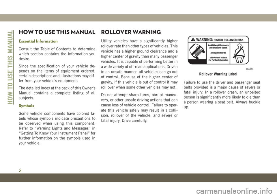
fatal injury. Drive carefully.Failure to use the driver and passenger seat
belts provided is a major cause of severe or
fatal injury. In a rollover crash, an unbelted
person is significantly more likely to die than
a person wearing a seat belt. Always buckle
up.
Rollover Warning Label
HOW TO USE THIS MANUAL
2
Page 7 of 344
GRAPHICAL TABLE OF CONTENTS
GETTING TO KNOW YOUR VEHICLE
GETTING TO KNOW YOUR INSTRUMENT PANEL
SAFETY
STARTING AND OPERATING
IN CASE OF EMERGENCY
SERVICING AND MAINTENANCE
TECHNICAL SPECIFICATIONS
MULTIMEDIA
CUSTOMER ASSISTANCE
INDEX
Page 8 of 344
WELCOME FROM FCA
HOW TO FIND YOUR OWNER’S MANUAL ONLINE.... 1
HOW TO USE THIS MANUAL
HOW TO USE THIS MANUAL.............. 2Essential Information................ 2
Symbols........................ 2
ROLLOVER WARNING................... 2
IMPORTANT NOTICE................... 3
WARNINGS AND CAUTIONS............... 4
VEHICLE MODIFICATIONS/ALTERATIONS........ 4
GRAPHICAL TABLE OF CONTENTS
INSTRUMENT PANEL.................. 11
INTERIOR......................... 12
GETTING TO KNOW YOUR VEHICLE
KEYS........................... 13KeyFob ....................... 13
IGNITION SWITCH.................... 15Ignition Node Module (IGNM) — If
Equipped...................... 15
Keyless Enter-N-Go (Ignition) — If Equipped . 16
REMOTE STARTING SYSTEM — IF EQUIPPED.... 17How To Use Remote Start............ 17
To Enter Remote Start Mode........... 18
VEHICLE SECURITY ALARM — IF EQUIPPED..... 19To Arm The System................ 19
To Disarm The System.............. 19
DOORS.......................... 20Keyless Enter-N-Go — Passive Entry...... 20
Locking The Doors With One Or More Doors
Open......................... 23
SEATS .......................... 23Manual Adjustment (Rear Seats)........ 23
Driver Memory Seat — If Equipped....... 25
Heated Seats.................... 26
Front Ventilated Seats — If Equipped..... 28
HEAD RESTRAINTS................... 28Reactive Head Restraints — Front Seats . . . 28
Rear Head Restraints............... 29
STEERING WHEEL.................... 31Tilt/Telescoping Steering Column........ 31
Heated Steering Wheel — If Equipped..... 31
MIRRORS........................ 32Power Folding Mirrors — If Equipped..... 32
EXTERIOR LIGHTS................... 32Multifunction Lever................ 32
Headlight Switch.................. 33
Daytime Running Lights (DRL) — If
Equipped...................... 33
High/Low Beam Switch.............. 34
Automatic High Beam Headlamp Control — If
Equipped...................... 34
Flash-To-Pass................... 34
Automatic Headlights — If Equipped..... 34
Parking Lights................... 34
Headlights On With Wipers (Available With
Automatic Headlights Only)........... 35
Adaptive Bi-Xenon High Intensity Discharge
Headlights — If Equipped............ 35
Headlight Time Delay............... 35
Lights-On Reminder................ 35
Front And Rear Fog Lights — If Equipped . . . 36
Turn Signals.................... 36
Automatic Headlight Leveling — HID Headlights
Only......................... 36
Battery Saver.................... 36
WINDSHIELD WIPERS AND WASHERS......... 37Windshield Wiper Operation........... 37
Rain Sensing Wipers — If Equipped...... 38
Rear Window Wiper/Washer........... 39
CLIMATE CONTROLS................... 40Climate Controls With A Touchscreen
Overview....................... 40
Climate Control Functions............ 47
Automatic Temperature Control (ATC) — If
Equipped...................... 48
Operating Tips................... 48
WINDOWS........................ 49Power Window Controls.............. 49
Auto-Up Feature With Anti-Pinch Protection . 50
Window Lockout Switch............. 50
Wind Buffeting.................. 50
POWER SUNROOF WITH POWER SHADE — IF
EQUIPPED........................ 51
Opening Sunroof.................. 52
Venting Sunroof.................. 52
Closing Sunroof.................. 52
Opening Power Shade............... 52
Closing Power Shade............... 53
Pinch Protect Feature............... 53
Sunroof Maintenance............... 53
Ignition Off Operation............... 53
HOOD.......................... 53Opening The Hood................. 53
Closing The Hood................. 54
LIFTGATE......................... 54Opening....................... 54
Closing........................ 56
Hands-Free Liftgate — If Equipped...... 56
TABLE OF CONTENTS
6
Page 9 of 344
INTERNAL EQUIPMENT................. 58Power Outlets................... 58
Power Inverter — If Equipped......... 60
ROOF LUGGAGE RACK — IF EQUIPPED......... 60
GETTING TO KNOW YOUR INSTRU-
MENT PANEL
INSTRUMENT CLUSTER DISPLAY............ 62Instrument Cluster Display Location And
Controls....................... 62
Instrument Cluster Display Selectable Items . 63
Diesel Displays................... 63
Diesel Particulate Filter (DPF) Messages . . . 63
WARNING LIGHTS AND MESSAGES.......... 64Red Warning Lights................ 64
Yellow Warning Lights............... 68
Yellow Indicator Lights.............. 72
Green Indicator Lights.............. 73
White Indicator Lights.............. 74
Blue Indicator Lights............... 75
ONBOARD DIAGNOSTIC SYSTEM — OBD II...... 75Onboard Diagnostic System (OBD II)
Cybersecurity.................... 76
SAFETY
SAFETY FEATURES................... 77Anti-Lock Brake System (ABS)......... 77
Electronic Brake Control System........ 78
AUXILIARY DRIVING SYSTEMS............. 88Blind Spot Monitoring (BSM) — If Equipped . 88
Forward Collision Warning (FCW) With Mitigation
— If Equipped................... 91
Tire Pressure Monitor System (TPMS)..... 94
OCCUPANT RESTRAINT SYSTEMS........... 98Occupant Restraint Systems Features..... 98
Important Safety Precautions.......... 98
Seat Belt Systems................ 100
Supplemental Restraint Systems (SRS) . . . 109
Child Restraints — Carrying Children
Safely....................... 119
Transporting Pets................ 135
SAFETY TIPS..................... 136Transporting Passengers............ 136
Exhaust Gas................... 136
Safety Checks You Should Make Inside The
Vehicle...................... 136
Periodic Safety Checks You Should Make
Outside The Vehicle............... 138
STARTING AND OPERATING
STARTING THE ENGINE................ 139Normal Starting — Gasoline Engine..... 139
Extreme Cold Weather
(Below –22°F Or −30°C)............ 140
Normal Starting — Diesel Engine....... 140
ENGINE BREAK-IN RECOMMENDATIONS....... 141
PARKING BRAKE.................... 142
Electric Park Brake (EPB)........... 142
MANUAL TRANSMISSION — IF EQUIPPED...... 144Shifting...................... 144
Downshifting................... 145
AUTOMATIC TRANSMISSION — IF EQUIPPED.... 146Key Ignition Park Interlock........... 147
Brake/Transmission Shift Interlock System . 148
Nine-Speed Automatic Transmission..... 148
Gear Ranges.................... 149
FOUR-WHEEL DRIVE OPERATION........... 1501-Speed Four-Wheel Drive (4X4) — If
Equipped..................... 150
2-Speed Four-Wheel Drive (4x4) — If
Equipped..................... 151
Shift Positions.................. 152
Shifting Procedures............... 152
Rear Electronic Locker (E-Locker) System — If
Equipped..................... 154
SELEC-TERRAIN.................... 155Description.................... 155
STOP/START SYSTEM................. 156Automatic Mode................. 156
Possible Reasons The Engine Does Not
Autostop...................... 157
To Start The Engine While In Autostop
Mode........................ 157
To Manually Turn Off The Stop/Start
System...................... 158
To Manually Turn On The Stop/Start System . 158
STOP/START SYSTEM — DIESEL MODELS ONLY . . 158Automatic Mode................. 159
Possible Reasons The Engine Does Not
Autostop...................... 159
To Start The Engine While In Autostop
Mode........................ 160
To Manually Turn Off The Stop/Start
System....................... 160
To Manually Turn On The Stop/Start System . 161
SPEED CONTROL.................... 161To Activate.................... 161
To Set A Desired Speed............. 162
To Resume Speed................ 162
To Deactivate................... 162
7
Page 13 of 344
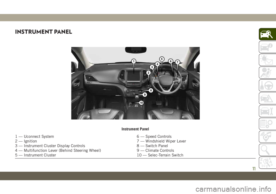
INSTRUMENT PANEL
Instrument Panel
1 — Uconnect System 6 — Speed Controls
2 — Ignition 7 — Windshield Wiper Lever
3 — Instrument Cluster Display Controls 8 — Switch Panel
4 — Multifunction Lever (Behind Steering Wheel) 9 — Climate Controls
5 — Instrument Cluster 10 — Selec-Terrain Switch
11
Page 15 of 344
KEYS
Key Fob
The key fob operates the ignition switch.
Insert the square end of the key fob into the
ignition switch located on the instrument
panel and rotate to the desired position. The
key fob also contains an emergency key,
which is stored in the rear of the key fob.
CAUTION!
The electrical components inside of the
key fob may be damaged if the key fob is
subjected to strong electrical shocks. In
order to ensure complete efficiency of the
electronic devices inside of the key fob,
avoid exposing the key fob to direct sun-
light.
Your vehicle may be equipped with a keyless
ignition system. The ignition system consists
of a key fob with Remote Keyless Entry (RKE)
and a START/STOP push button ignition sys-
tem. The Remote Keyless Entry system con-
sists of a key fob and Keyless Enter-N-Go
feature if equipped.
NOTE:
The key fob may not be found if it is located
next to a mobile phone, laptop or other elec-
tronic device; these devices may block the
key fob’s wireless signal.
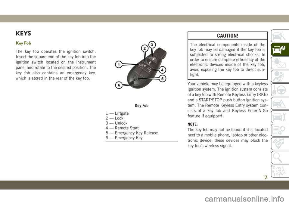
Key Fob
1 — Liftgate
2 — Lock
3 — Unlock
4 — Remote Start
5 — Emergency Key Release
6 — Emergency Key
13
Page 27 of 344
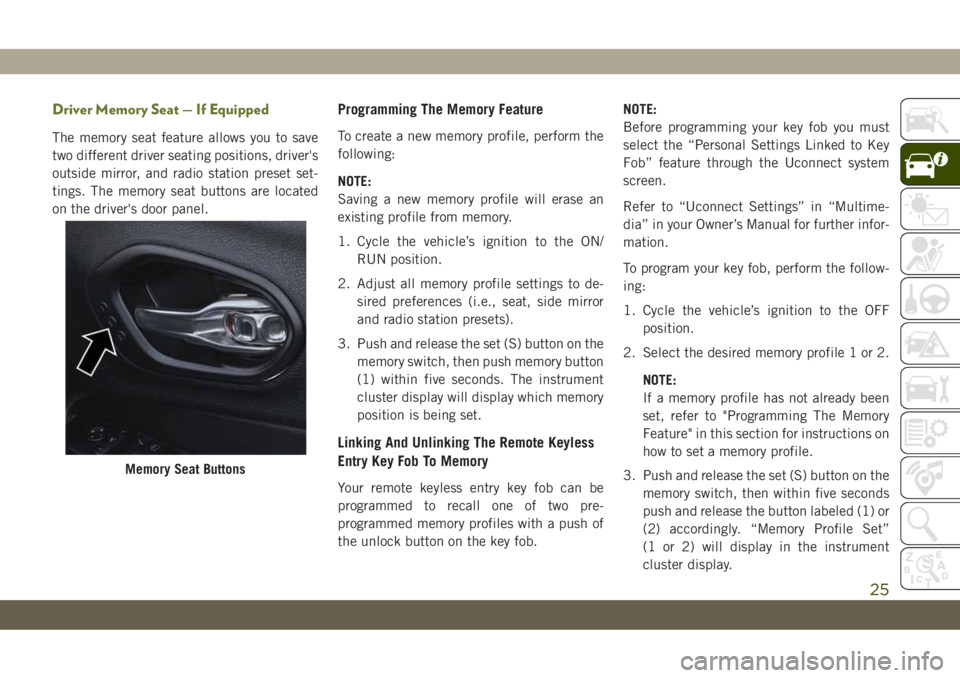
Driver Memory Seat — If Equipped
The memory seat feature allows you to save
two different driver seating positions, driver's
outside mirror, and radio station preset set-
tings. The memory seat buttons are located
on the driver's door panel.
Programming The Memory Feature
To create a new memory profile, perform the
following:
NOTE:
Saving a new memory profile will erase an
existing profile from memory.
1. Cycle the vehicle’s ignition to the ON/
RUN position.
2. Adjust all memory profile settings to de-
sired preferences (i.e., seat, side mirror
and radio station presets).
3. Push and release the set (S) button on the
memory switch, then push memory button
(1) within five seconds. The instrument
cluster display will display which memory
position is being set.
Linking And Unlinking The Remote Keyless
Entry Key Fob To Memory
Your remote keyless entry key fob can be
programmed to recall one of two pre-
programmed memory profiles with a push of
the unlock button on the key fob.NOTE:
Before programming your key fob you must
select the “Personal Settings Linked to Key
Fob” feature through the Uconnect system
screen.
Refer to “Uconnect Settings” in “Multime-
dia” in your Owner’s Manual for further infor-
mation.
To program your key fob, perform the follow-
ing:
1. Cycle the vehicle’s ignition to the OFF
position.
2. Select the desired memory profile 1 or 2.
NOTE:
If a memory profile has not already been
set, refer to "Programming The Memory
Feature" in this section for instructions on
how to set a memory profile.
3. Push and release the set (S) button on the
memory switch, then within five seconds
push and release the button labeled (1) or
(2) accordingly. “Memory Profile Set”
(1 or 2) will display in the instrument
cluster display.
Memory Seat Buttons
25
Page 35 of 344
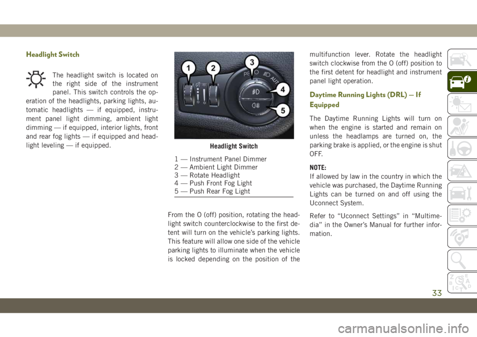
Headlight Switch
The headlight switch is located on
the right side of the instrument
panel. This switch controls the op-
eration of the headlights, parking lights, au-
tomatic headlights — if equipped, instru-
ment panel light dimming, ambient light
dimming — if equipped, interior lights, front
and rear fog lights — if equipped and head-
light leveling — if equipped.
From the O (off) position, rotating the head-
light switch counterclockwise to the first de-
tent will turn on the vehicle’s parking lights.
This feature will allow one side of the vehicle
parking lights to illuminate when the vehicle
is locked depending on the position of themultifunction lever. Rotate the headlight
switch clockwise from the O (off) position to
the first detent for headlight and instrument
panel light operation.
Daytime Running Lights (DRL) — If
Equipped
The Daytime Running Lights will turn on
when the engine is started and remain on
unless the headlamps are turned on, the
parking brake is applied, or the engine is shut
OFF.
NOTE:
If allowed by law in the country in which the
vehicle was purchased, the Daytime Running
Lights can be turned on and off using the
Uconnect System.
Refer to “Uconnect Settings” in “Multime-
dia” in the Owner’s Manual for further infor-
mation.
Headlight Switch
1 — Instrument Panel Dimmer
2 — Ambient Light Dimmer
3 — Rotate Headlight
4 — Push Front Fog Light
5 — Push Rear Fog Light
33
Page 48 of 344
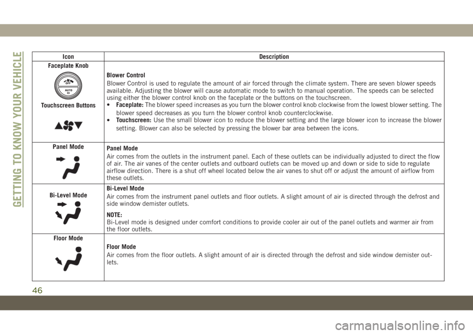
Icon Description
Faceplate Knob
Touchscreen Buttons
Blower Control
Blower Control is used to regulate the amount of air forced through the climate system. There are seven blower speeds
available. Adjusting the blower will cause automatic mode to switch to manual operation. The speeds can be selected
using either the blower control knob on the faceplate or the buttons on the touchscreen.
•Faceplate:The blower speed increases as you turn the blower control knob clockwise from the lowest blower setting. The
blower speed decreases as you turn the blower control knob counterclockwise.
•Touchscreen:Use the small blower icon to reduce the blower setting and the large blower icon to increase the blower
setting. Blower can also be selected by pressing the blower bar area between the icons.
Panel Mode
Panel Mode
Air comes from the outlets in the instrument panel. Each of these outlets can be individually adjusted to direct the flow
of air. The air vanes of the center outlets and outboard outlets can be moved up and down or side to side to regulate
airflow direction. There is a shut off wheel located below the air vanes to shut off or adjust the amount of airflow from
these outlets.
Bi-Level Mode
Bi-Level Mode
Air comes from the instrument panel outlets and floor outlets. A slight amount of air is directed through the defrost and
side window demister outlets.
NOTE:
Bi-Level mode is designed under comfort conditions to provide cooler air out of the panel outlets and warmer air from
the floor outlets.
Floor Mode
Floor Mode
Air comes from the floor outlets. A slight amount of air is directed through the defrost and side window demister out-
lets.
GETTING TO KNOW YOUR VEHICLE
46
Page 55 of 344
and stop automatically. This is called “Ex-
press Open”. During Express Open operation,
any movement of the sunshade switch will
stop the shade.
Manual Mode
Push and hold the sunshade switch rearward,
the shade will open to the half open position
and stop automatically. Push and hold the
sunshade switch rearward again and the
shade will open automatically to the full-open
position. Any release of the switch will stop
the movement and the sunshade will remain
in a partially opened condition until the
switch is pushed again.
Closing Power Shade
If the sunroof is open or vented the sunshade
cannot be closed beyond the half open posi-
tion. Pushing the sunshade close switch
when the sunroof is open/vented and the
sunshade is at half open position will first
automatically close sunroof prior to the sun-
shade closing.Express
Push the switch forward and release it within
one-half second and the shade will close
automatically from any position.
Manual
To close the shade, push and hold the switch
in the forward position.
Pinch Protect Feature
This feature will detect an obstruction in the
closing of the sunroof during the Express
Close operation. If an obstruction in the path
of the sunroof is detected, the sunroof will
automatically retract. Remove the obstruc-
tion if this occurs.
NOTE:
If three consecutive sunroof close attempts
result in Pinch Protect reversals, Pinch Pro-
tect will disable and the sunroof must be
closed in Manual Mode.
Sunroof Maintenance
Use only a non-abrasive cleaner and a soft
cloth to clean the glass panel.
Ignition Off Operation
The power sunroof switch will remain active
for up to approximately 10 minutes after the
ignition switch is turned to the OFF/LOCK
position. Opening either front door will can-
cel this feature.
NOTE:
Ignition Off time is programmable through
the Uconnect System. Refer to “Uconnect
Settings” in “Multimedia” in your Owner’s
Manual for further information.
HOOD
Opening The Hood
Two latches must be released to open the
hood.
1. Pull the hood release lever located under
the driver’s side of the instrument panel.
53