battery location JEEP CHEROKEE 2023 Owners Manual
[x] Cancel search | Manufacturer: JEEP, Model Year: 2023, Model line: CHEROKEE, Model: JEEP CHEROKEE 2023Pages: 276, PDF Size: 12.55 MB
Page 2 of 276

WARNING: Operating, servicing and maintaining a passenger vehicle or off-highway
motor vehicle can expose you to chemicals including engine exhaust, carbon monoxide,
phthalates, and lead, which are known to the State of California to cause cancer and
birth defects or other reproductive harm. To minimize exposure, avoid breathing exhaust,
do not idle the engine except as necessary, service your vehicle in a well-ventilated area
and wear gloves or wash your hands frequently when servicing your vehicle. For more
information go to www.P65Warnings.ca.gov/passenger-vehicle.
This Owner’s Manual illustrates and describes the operation of features and equipment that are either standard or optional on this vehicle. This manual may also include a description of features and equipment that are no longer available or were not ordered on this vehicle. Please disregard any features and equipment described in this manual that are not on this vehicle. FCA US LLC reserves the right to make changes in design and specifications, and/or make additions to or improvements to its products without imposing any obligation upon itself to install them on products previously manufactured.
With respect to any vehicles sold in Canada, the name FCA US LLC shall be deemed to be deleted and the name FCA Canada Inc. used in substitution therefore.
This Owner’s Manual is intended to familiarize you with the important features of your vehicle. Your most up-to-date Owner’s Manual, Navigation/Uconnect manuals and Warranty Booklet can be found by visiting the website on the back cover.
ROADSIDE ASSISTANCE 24 HOURS, 7 DAYS A WEEK AT YOUR SERVICE. CALL 1-800-521-2779 OR VISIT CHRYSLER.RSAHELP.COM (USA) CALL 1-800-363-4869 OR VISIT FCA.ROADSIDEAID.COM (CANADA) SERVICES: Flat Tire Service, Out Of Gas/Fuel Delivery, Battery Jump Assistance, Lockout Service and Towing Service
Please see the Customer Assistance chapter in this Owner’s Manual for further information.
FCA US LLC reserves the right to modify the terms or discontinue the Roadside Assistance Program at any time. The Roadside Assistance Program is subject to restrictions and conditions of use, that are determined solely by FCA US LLC.
The driver’s primary responsibility is the safe operation of the vehicle. Driving while distracted can result in loss of vehicle control, resulting in an accident and personal injury. FCA US LLC strongly recommends that the driver use extreme caution when using any device or feature that may take their attention off the road. Use of any electrical devices, such as cellular telephones, computers, portable radios, vehicle navigation or other devices by the driver while the vehicle is moving is dangerous and could lead to a serious accident. Texting while driving is also dangerous and should never be done while the vehicle is moving. If you find yourself unable to devote your full attention to vehicle operation, pull off the road to a safe location and stop your vehicle. Some states or provinces prohibit the use of cellular telephones or texting while driving. It is always the driver’s responsibility to comply with all local laws.
This Owner’s Manual has been prepared to help you get acquainted with your new Jeep® brand vehicle and to provide a convenient reference source for common questions.
Not all features shown in this manual may apply to your vehicle. For additional information, visit mopar.com/om (USA), owners.mopar.ca (Canada) or your local Jeep® brand dealer.
U.S. Residents: If you are the first registered retail owner of your vehicle, you may obtain a complimentary printed copy of the Warranty Booklet by calling 1-877-426-5337 or by contacting your dealer. Replacement kits can be purchased by visiting www.techauthority.com.
Canadian Residents: If you are the first registered retail owner of your vehicle, you may obtain a complimentary printed copy of the Warranty Booklet or purchase a replacement kit by calling 1-800-387-1143 or by contacting your dealer.
DRIVING AND ALCOHOL
Drunk driving is one of the most frequent causes of accidents. Your driving ability can be seriously impaired with blood alcohol levels far below the legal minimum. If you are drinking, don’t drive. Ride with a designated non-drinking driver, call a cab, a rideshare, a friend or use public transportation.
WARNING
Driving after drinking can lead to an accident. Your perceptions are less sharp, your reflexes are slower and your judgment is impaired when you have been drinking. Never drink and then drive.
Page 5 of 276
3
WINDSHIELD WIPERS AND WASHERS ........................... 43Windshield Wiper Operation....................................... 44
Rain Sensing Wipers — If Equipped .......................... 44
Rear Window Wiper/Washer ..................................... 45
Windshield Wiper De-Icer — If Equipped ................... 45
CLIMATE CONTROLS ..........................................................45 Automatic Climate Control Descriptions And
Functions ..................................................................... 45
Automatic Temperature Control (ATC) —
If Equipped ................................................................. 48
Climate Voice Commands .......................................... 48
Operating Tips ............................................................ 48
INTERIOR STORAGE AND EQUIPMENT ............................49 Storage ........................................................................ 49
AUX/USB Control ........................................................ 50
Power Outlets .............................................................. 51
Power Inverter — If Equipped .................................... 52
WINDOWS ...........................................................................53 Power Window Controls .............................................. 53
Automatic Window Features ..................................... 53
Reset Auto-Up.............................................................. 53
Window Lockout Switch.............................................. 54
Wind Buffeting ............................................................ 54
POWER SUNROOF WITH POWER SHADE —
IF EQUIPPED ....................................................................... 54 Opening And Closing The Sunroof ............................. 55
Opening And Closing The Power Shade .................... 55
Pinch Protect Feature ................................................. 56
Venting Sunroof .......................................................... 56
Ignition Off Operation.................................................. 56
Sunroof Maintenance ................................................. 56
HOOD ...................................................................................56 Opening The Hood ...................................................... 56
Closing The Hood ........................................................ 57 LIFTGATE .............................................................................. 57
To Unlock/Open The Liftgate ......................................57
To Lock/Close The Liftgate ......................................... 58
Hands-Free Liftgate — If Equipped ............................ 58
Cargo Area Features ................................................... 59
ROOF LUGGAGE RACK — IF EQUIPPED .......................... 60
GETTING TO KNOW YOUR
INSTRUMENT PANEL
INSTRUMENT CLUSTER ..................................................... 61 Instrument Cluster Descriptions ................................. 63
INSTRUMENT CLUSTER DISPLAY
S
.............................. 63
Instrument Cluster Display Location And Controls.... 63
Oil Life Reset — If Equipped
S
................................. 64
Instrument Cluster Display Menu Items ................... 64
Instrument Cluster Display Selectable Items ............ 67
Battery Saver On/Battery Saver Mode Message —
Electrical Load Reduction Actions — If Equipped .....67
WARNING LIGHTS AND MESSAGES ................................ 68 Red Warning Lights ..................................................... 68
Yellow Warning Lights ................................................. 70
Yellow Indicator Lights ................................................ 73
Green Indicator Lights ................................................. 73
White Indicator Lights.................................................. 74
Blue Indicator Lights.................................................... 75
ONBOARD DIAGNOSTIC SYSTEM — OBD II ..................... 75 Onboard Diagnostic System (OBD II)
Cybersecurity ...............................................................75
EMISSIONS INSPECTION AND MAINTENANCE
PROGRAMS ........................................................................ 75
STARTING AND OPERATING
STARTING THE ENGINE ..................................................... 77 Normal Starting ........................................................... 77
Extreme Cold Weather (Below –20°F Or −29°C) .... 77
Extended Park Starting ............................................... 77
If Engine Fails To Start ............................................... 78
After Starting................................................................ 78
ENGINE BREAK-IN RECOMMENDATIONS........................ 78
PARKING BRAKE ................................................................ 78 Electric Park Brake (EPB) ........................................... 78
AUTOMATIC TRANSMISSION ............................................ 81 Key Ignition Park Interlock.......................................... 81
Brake/Transmission Shift Interlock (BTSI) System ... 81
9-Speed Automatic Transmission ............................. 81
Gear Ranges ................................................................ 82
FOUR-WHEEL DRIVE OPERATION .................................... 85 1-Speed Four-Wheel Drive (4WD) — If Equipped....... 85
2-Speed Four-Wheel Drive (4WD) — If Equipped....... 85
Shift Positions.............................................................. 86
Shifting Procedures ..................................................... 86
Rear Electronic Locker System — If Equipped........... 87
SELEC-TERRAIN .................................................................. 88 Description................................................................... 88
POWER STEERING ............................................................. 88
STOP/START SYSTEM........................................................ 89 Autostop Mode ............................................................ 89
Possible Reasons The Engine Does Not Autostop .... 89
To Start The Engine While In Autostop Mode ............ 89
To Manually Turn Off The Stop/Start System............ 90
To Manually Turn On The Stop/Start System ............ 90
System Malfunction .................................................... 90
23_KL_OM_EN_USC_t.book Page 3
Page 7 of 276
5
IN CASE OF EMERGENCY
HAZARD WARNING FLASHERS ..................................... 189
SOS AND ASSIST MIRROR ............................................. 189
JACKING AND TIRE CHANGING ..................................... 191 Preparations For Jacking .......................................... 192
Jack Location/Spare Tire Stowage .......................... 192Jacking Instructions .................................................. 193
TIRE SERVICE KIT — IF EQUIPPED ................................. 196 Tire Service Kit Storage ............................................ 196
Tire Service Kit Components And Operation ........... 196Tire Service Kit Usage Precautions ......................... 197Sealing A Tire With Tire Service Kit .......................... 198
JUMP STARTING ............................................................... 200 Preparations For Jump Start .................................... 200
Jump Starting Procedure .......................................... 201
REFUELING IN EMERGENCY – IF EQUIPPED ............... 202
IF YOUR ENGINE OVERHEATS ....................................... 203
GEAR SELECTOR OVERRIDE .......................................... 203
FREEING A STUCK VEHICLE ........................................... 204
TOWING A DISABLED VEHICLE ...................................... 205 Front-Wheel Drive (FWD) Models ............................. 206
4x4 Models With 1–Speed Power Transfer Unit..... 2064x4 Models With 2–Speed Power Transfer Unit..... 206Emergency Tow Hooks — If Equipped ..................... 206
Recovery Strap — If Equipped .................................. 207
ENHANCED ACCIDENT RESPONSE SYSTEM (EARS) .. 207
EVENT DATA RECORDER (EDR) ..................................... 207
SERVICING AND MAINTENANCE
SCHEDULED SERVICING ................................................ 208 Maintenance Plan ..................................................... 209 ENGINE COMPARTMENT ................................................ 212
2.0L Engine .............................................................. 212
2.4L Engine .............................................................. 213
Checking Oil Level .................................................... 214
Adding Washer Fluid ................................................ 214
Maintenance-Free Battery ...................................... 214
Pressure Washing ..................................................... 215
VEHICLE MAINTENANCE ................................................. 215 Engine Oil ................................................................. 215Engine Oil Filter ......................................................... 216Engine Air Cleaner Filter ........................................... 216Accessory Drive Belt Inspection............................... 217
Air Conditioner Maintenance ................................... 217Body Lubrication ....................................................... 219
Windshield Wiper Blades ........................................ 219
Exhaust System ....................................................... 222
Cooling System ......................................................... 222Brake System ........................................................... 225
Automatic Transmission........................................... 225Fuses ......................................................................... 226
Bulb Replacement ................................................... 233
TIRES ................................................................................ 235 Tire Safety Information ............................................. 235
Tires — General Information..................................... 241
Tire Types .................................................................. 244
Spare Tires — If Equipped ....................................... 244
Wheel And Wheel Trim Care .................................... 245Snow Traction Devices ............................................ 246
Tire Rotation Recommendations ............................. 248
DEPARTMENT OF TRANSPORTATION UNIFORM
TIRE QUALITY GRADES .................................................. 249 Treadwear ................................................................. 249Traction Grades ........................................................ 249Temperature Grades ................................................ 249 STORING THE VEHICLE ....................................................250
BODYWORK ......................................................................250
Protection From Atmospheric Agents ...................... 250
Body And Underbody Maintenance.......................... 250
Preserving The Bodywork ......................................... 250
INTERIORS ........................................................................ 251 Seats And Fabric Parts.............................................. 251Plastic And Coated Parts .......................................... 251
Leather Surfaces ....................................................... 252
Glass Surfaces .......................................................... 252
TECHNICAL SPECIFICATIONS
VEHICLE IDENTIFICATION NUMBER (VIN) ..................... 253
BRAKE SYSTEM ................................................................ 253
WHEEL AND TIRE TORQUE SPECIFICATIONS ...............253 Torque Specifications ............................................... 253
FUEL REQUIREMENTS......................................................254 2.0L Engine................................................................ 254
2.4L Engine................................................................ 254
Reformulated Gasoline ............................................. 254Gasoline/Oxygenate Blends ..................................... 254
Do Not Use E-85 In Non-Flex Fuel Vehicles ............. 255
CNG And LP Fuel System Modifications .................. 255Methylcyclopentadienyl Manganese Tricarbonyl
(MMT) In Gasoline ..................................................... 255Materials Added To Fuel ........................................... 255
Fuel System Cautions ............................................... 255
FLUID CAPACITIES............................................................256
ENGINE FLUIDS AND LUBRICANTS ................................256
CHASSIS FLUIDS AND LUBRICANTS ..............................257
23_KL_OM_EN_USC_t.book Page 5
Page 19 of 276
GETTING TO KNOW YOUR VEHICLE17
(Continued)
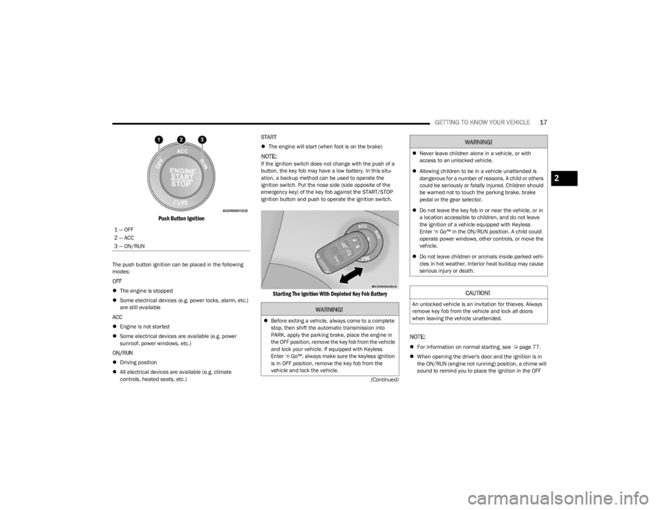
Push Button Ignition
The push button ignition can be placed in the following
modes:
OFF
The engine is stopped
Some electrical devices (e.g. power locks, alarm, etc.)
are still available
ACC
Engine is not started
Some electrical devices are available (e.g. power
sunroof, power windows, etc.)
ON/RUN
Driving position
All electrical devices are available (e.g. climate
controls, heated seats, etc.) START
The engine will start (when foot is on the brake)
NOTE:If the ignition switch does not change with the push of a
button, the key fob may have a low battery. In this situ -
ation, a backup method can be used to operate the
ignition switch. Put the nose side (side opposite of the
emergency key) of the key fob against the START/STOP
ignition button and push to operate the ignition switch.
Starting The Ignition With Depleted Key Fob Battery
NOTE:
For information on normal starting, see Úpage 77.
When opening the driver's door and the ignition is in
the ON/RUN (engine not running) position, a chime will
sound to remind you to place the ignition in the OFF
1 — OFF
2 — ACC
3 — ON/RUN
WARNING!
Before exiting a vehicle, always come to a complete
stop, then shift the automatic transmission into
PARK, apply the parking brake, place the engine in
the OFF position, remove the key fob from the vehicle
and lock your vehicle. If equipped with Keyless
Enter ‘n Go™, always make sure the keyless ignition
is in OFF position, remove the key fob from the
vehicle and lock the vehicle.
Never leave children alone in a vehicle, or with
access to an unlocked vehicle.
Allowing children to be in a vehicle unattended is
dangerous for a number of reasons. A child or others
could be seriously or fatally injured. Children should
be warned not to touch the parking brake, brake
pedal or the gear selector.
Do not leave the key fob in or near the vehicle, or in
a location accessible to children, and do not leave
the ignition of a vehicle equipped with Keyless
Enter ‘n Go™ in the ON/RUN position. A child could
operate power windows, other controls, or move the
vehicle.
Do not leave children or animals inside parked vehi -
cles in hot weather. Interior heat buildup may cause
serious injury or death.
CAUTION!
An unlocked vehicle is an invitation for thieves. Always
remove key fob from the vehicle and lock all doors
when leaving the vehicle unattended.
WARNING!
2
23_KL_OM_EN_USC_t.book Page 17
Page 25 of 276
GETTING TO KNOW YOUR VEHICLE23
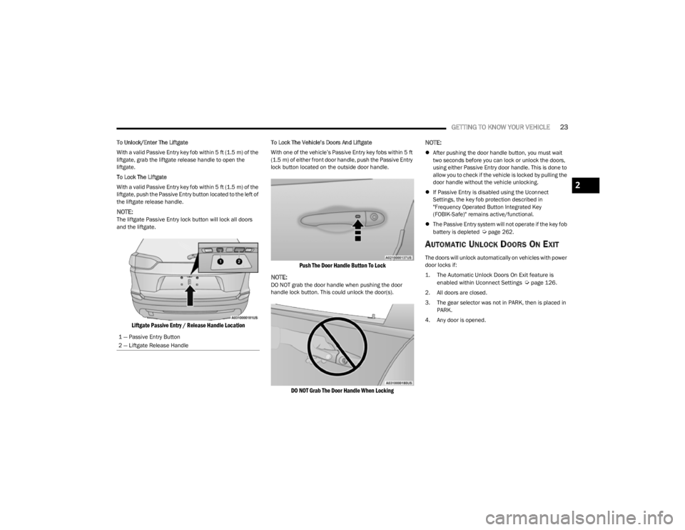
To Unlock/Enter The Liftgate
With a valid Passive Entry key fob within 5 ft (1.5 m) of the
liftgate, grab the liftgate release handle to open the
liftgate.
To Lock The Liftgate
With a valid Passive Entry key fob within 5 ft (1.5 m) of the liftgate, push the Passive Entry button located to the left of
the liftgate release handle.
NOTE:The liftgate Passive Entry lock button will lock all doors
and the liftgate.
Liftgate Passive Entry / Release Handle Location
To Lock The Vehicle’s Doors And Liftgate
With one of the vehicle’s Passive Entry key fobs within 5 ft
(1.5 m) of either front door handle, push the Passive Entry
lock button located on the outside door handle.
Push The Door Handle Button To Lock
NOTE:
DO NOT grab the door handle when pushing the door
handle lock button. This could unlock the door(s).
DO NOT Grab The Door Handle When Locking
NOTE:
After pushing the door handle button, you must wait
two seconds before you can lock or unlock the doors,
using either Passive Entry door handle. This is done to
allow you to check if the vehicle is locked by pulling the
door handle without the vehicle unlocking.
If Passive Entry is disabled using the Uconnect
Settings, the key fob protection described in
"Frequency Operated Button Integrated Key
(FOBIK-Safe)" remains active/functional.
The Passive Entry system will not operate if the key fob
battery is depleted
Úpage 262.
AUTOMATIC UNLOCK DOORS ON EXIT
The doors will unlock automatically on vehicles with power
door locks if:
1. The Automatic Unlock Doors On Exit feature is
enabled within Uconnect Settings
Ú
page 126.
2. All doors are closed.
3. The gear selector was not in PARK, then is placed in PARK.
4. Any door is opened.
1 — Passive Entry Button
2 — Liftgate Release Handle
2
23_KL_OM_EN_USC_t.book Page 23
Page 53 of 276
GETTING TO KNOW YOUR VEHICLE51
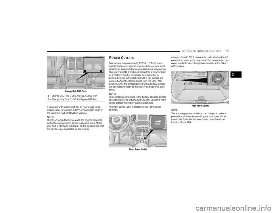
Charge Only USB Ports
If equipped with a Uconnect 4C/4C NAV with 8.4-inch
Display, refer to “Android Auto™” or “Apple CarPlay®” in
the Uconnect Radio Instruction Manual.
NOTE:Charge unsupported devices with the Charge Only USB
ports. If an unsupported device is plugged into a Media
USB port, a message will display on the touchscreen that
the device is not supported by the system.
POWER OUTLETS
Your vehicle is equipped with 12 Volt (13 Amp) power
outlets that can be used to power cellular phones, small
electronics, and other low powered electrical accessories.
The power outlets are labeled with either a “key” symbol
or a “battery” symbol to indicate how the outlet is
powered. Power outlets labeled with a key symbol are
powered when the ignition switch is in the ON or ACC
position, while the outlets labeled with a battery symbol
are connected directly to the battery and powered at all
times.
NOTE:All accessories connected to the battery powered outlets
should be removed or turned off when the vehicle is not in
use to protect the battery against discharge.
The front power outlet is located in front of the gear
selector.
Front Power Outlet
A second fused 12 Volt power outlet is located on the left
quarter trim panel in the cargo area. This power outlet has
power available when the ignition switch is in the ON or
ACC position.
Rear Power Outlet
NOTE:
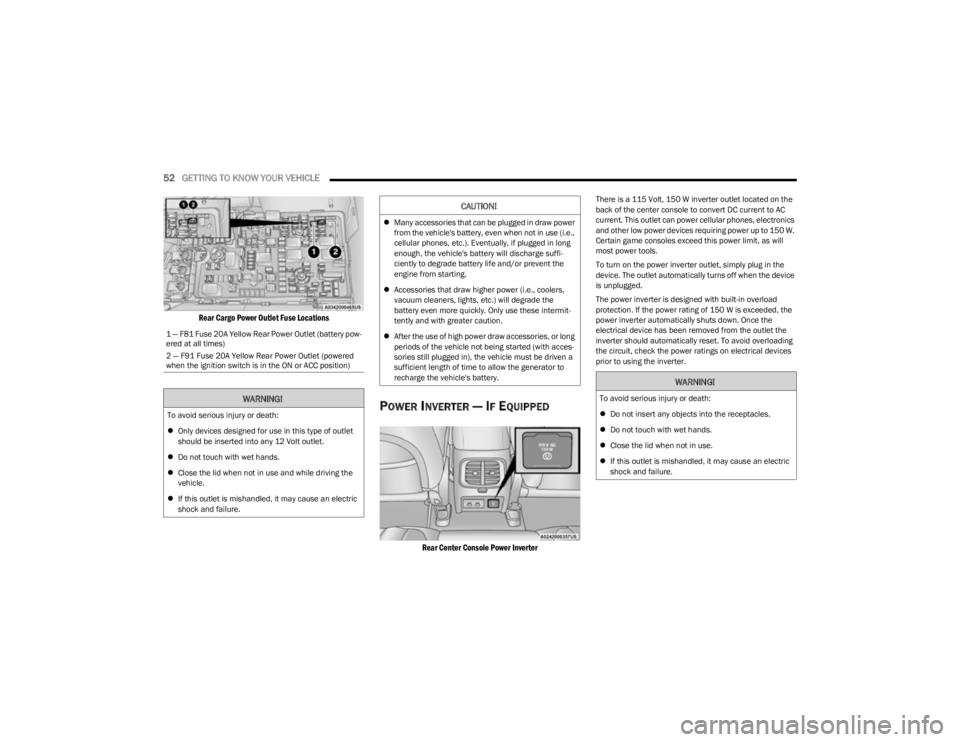
The rear cargo power outlet can be changed to battery
powered at all times by switching the rear power outlet
fuse in the Power Distribution Center panel from fuse
location F91 to F81.
1 — Charge Only Type C USB And Type A USB Port
2 — Charge Only Type C USB And Type A USB Port
2
23_KL_OM_EN_USC_t.book Page 51
Page 54 of 276
52GETTING TO KNOW YOUR VEHICLE
Rear Cargo Power Outlet Fuse Locations
POWER INVERTER — IF EQUIPPED
Rear Center Console Power Inverter
There is a 115 Volt, 150 W inverter outlet located on the
back of the center console to convert DC current to AC
current. This outlet can power cellular phones, electronics
and other low power devices requiring power up to 150 W.
Certain game consoles exceed this power limit, as will
most power tools.
To turn on the power inverter outlet, simply plug in the
device. The outlet automatically turns off when the device
is unplugged.
The power inverter is designed with built-in overload
protection. If the power rating of 150 W is exceeded, the
power inverter automatically shuts down. Once the
electrical device has been removed from the outlet the
inverter should automatically reset. To avoid overloading
the circuit, check the power ratings on electrical devices
prior to using the inverter.
1 — F81 Fuse 20A Yellow Rear Power Outlet (battery pow
-
ered at all times)
2 — F91 Fuse 20A Yellow Rear Power Outlet (powered
when the ignition switch is in the ON or ACC position)
WARNING!
To avoid serious injury or death:
Only devices designed for use in this type of outlet
should be inserted into any 12 Volt outlet.
Do not touch with wet hands.
Close the lid when not in use and while driving the
vehicle.
If this outlet is mishandled, it may cause an electric
shock and failure.
CAUTION!
Many accessories that can be plugged in draw power
from the vehicle's battery, even when not in use (i.e.,
cellular phones, etc.). Eventually, if plugged in long
enough, the vehicle's battery will discharge suffi -
ciently to degrade battery life and/or prevent the
engine from starting.
Accessories that draw higher power (i.e., coolers,
vacuum cleaners, lights, etc.) will degrade the
battery even more quickly. Only use these intermit -
tently and with greater caution.
After the use of high power draw accessories, or long
periods of the vehicle not being started (with acces -
sories still plugged in), the vehicle must be driven a
sufficient length of time to allow the generator to
recharge the vehicle's battery.
WARNING!
To avoid serious injury or death:
Do not insert any objects into the receptacles.
Do not touch with wet hands.
Close the lid when not in use.
If this outlet is mishandled, it may cause an electric
shock and failure.
23_KL_OM_EN_USC_t.book Page 52
Page 79 of 276
77
STARTING AND OPERATING
STARTING THE ENGINE
Before starting your vehicle, adjust your seat, adjust both
inside and outside mirrors, and fasten your seat belts.
Start the engine with the gear selector in the NEUTRAL (N)
or PARK (P) position. Apply the brake before shifting to any
driving range.
NORMAL STARTING
Press the brake pedal and place the ignition in the START
position and release when the engine starts. If the engine
fails to start within 10 seconds:
1. Place the ignition in the OFF position.
2. Wait 10 to 15 seconds.
3. Repeat the “Normal Starting” procedure.
NOTE:Only press one pedal at a time while driving the vehicle.
Torque performance of the vehicle could be reduced if
both pedals are pressed at the same time. If pressure is
detected on both pedals simultaneously, a warning
message will display in the instrument cluster
Úpage 63.
Tip Start Feature
Place the ignition in the START position and release it as
the starter engages. The starter motor will automatically
disengage itself once the engine is running. If the engine
fails to start, the starter will disengage automatically in
10 seconds. If this occurs:
1. Place the ignition in the OFF position.
2. Wait 10 to 15 seconds.
3. Repeat the “Normal Starting” procedure.
EXTREME COLD WEATHER
(B
ELOW –20°F OR −29°C)
To ensure reliable starting at these temperatures, use of
an externally powered electric engine block heater
(available from an authorized dealer) is recommended.
EXTENDED PARK STARTING
NOTE:Extended Park condition occurs when the vehicle has not
been started or driven for at least 30 days.
1. Install a battery charger or jumper cables to the
battery to ensure a full battery charge during the
crank cycle.
2. Place the ignition in the START position and release it when the engine starts. For Keyless Enter ‘n Go™
ignition systems, press and hold the brake pedal
while pushing the ENGINE START/STOP button once.
3. If the engine fails to start within 10 seconds, place the ignition in the OFF position, wait 10 to 15 seconds
to allow the starter to cool, then repeat the Extended
Park Starting procedure.
4. If the engine fails to start after eight attempts, allow the starter to cool for at least 10 minutes, then repeat
the procedure.
WARNING!
When leaving the vehicle, always remove the key fob
from the ignition and lock your vehicle. If equipped
with Keyless Enter ‘n Go™, always make sure the
keyless ignition node is in OFF position, remove the
key fob from the vehicle and lock the vehicle.
Never leave children alone in a vehicle, or with
access to an unlocked vehicle.
Allowing children to be in a vehicle unattended is
dangerous for a number of reasons. A child or others
could be seriously or fatally injured. Children should
be warned not to touch the parking brake, brake
pedal or the gear selector.
Do not leave the key fob in or near the vehicle, or in
a location accessible to children, and do not leave
the ignition of a vehicle equipped with Keyless
Enter ‘n Go™ in the ACC or ON/RUN position. A child
could operate power windows, other controls, or
move the vehicle.
4
23_KL_OM_EN_USC_t.book Page 77
Page 169 of 276
SAFETY167
(Continued)
The ORC contains a backup power supply system that may
deploy the air bag system even if the battery loses power
or it becomes disconnected prior to deployment.
The ORC turns on the Air Bag Warning Light in the
instrument panel for approximately four to eight seconds
for a self-check when the ignition switch is first in the ON/
RUN position. After the self-check, the Air Bag Warning
Light will turn off. If the ORC detects a malfunction in any
part of the system, it turns on the Air Bag Warning Light,
either momentarily or continuously. A single chime will
sound to alert you if the light comes on again after initial
startup.
The ORC also includes diagnostics that will illuminate the
instrument panel Air Bag Warning Light if a malfunction is
detected that could affect the air bag system. The
diagnostics also record the nature of the malfunction.
While the air bag system is designed to be maintenance
free, if any of the following occurs, have an authorized
dealer service the air bag system immediately.
The Air Bag Warning Light does not come on during the
four to eight seconds when the ignition switch is first in
the ON/RUN position.
The Air Bag Warning Light remains on after the four to
eight-second interval.
The Air Bag Warning Light comes on intermittently or
remains on while driving.
NOTE:If the speedometer, tachometer, or any engine related
gauges are not working, the Occupant Restraint Controller
(ORC) may also be disabled. In this condition the air bags
may not be ready to inflate for your protection. Have an
authorized dealer service the air bag system immediately.
Redundant Air Bag Warning Light
If a fault with the Air Bag Warning Light is
detected, which could affect the Supplemental
Restraint System (SRS), the Redundant Air Bag
Warning Light will illuminate on the instrument
panel. The Redundant Air Bag Warning Light will stay on
until the fault is cleared. In addition, a single chime will
sound to alert you that the Redundant Air Bag Warning
Light has come on and a fault has been detected. If the
Redundant Air Bag Warning Light comes on intermittently
or remains on while driving have an authorized dealer
service the vehicle immediately
Úpage 68.
Front Air Bags
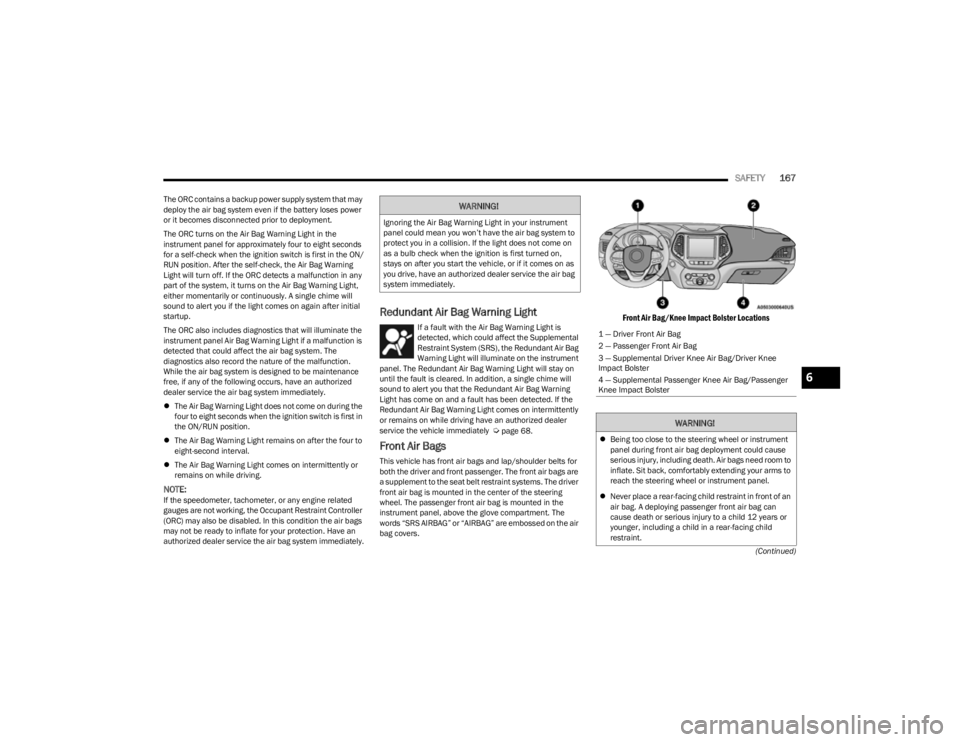
This vehicle has front air bags and lap/shoulder belts for
both the driver and front passenger. The front air bags are
a supplement to the seat belt restraint systems. The driver
front air bag is mounted in the center of the steering
wheel. The passenger front air bag is mounted in the
instrument panel, above the glove compartment. The
words “SRS AIRBAG” or “AIRBAG” are embossed on the air
bag covers.
Front Air Bag/Knee Impact Bolster Locations
WARNING!
Ignoring the Air Bag Warning Light in your instrument
panel could mean you won’t have the air bag system to
protect you in a collision. If the light does not come on
as a bulb check when the ignition is first turned on,
stays on after you start the vehicle, or if it comes on as
you drive, have an authorized dealer service the air bag
system immediately.
1 — Driver Front Air Bag
2 — Passenger Front Air Bag
3 — Supplemental Driver Knee Air Bag/Driver Knee
Impact Bolster
4 — Supplemental Passenger Knee Air Bag/Passenger
Knee Impact Bolster
WARNING!
Being too close to the steering wheel or instrument
panel during front air bag deployment could cause
serious injury, including death. Air bags need room to
inflate. Sit back, comfortably extending your arms to
reach the steering wheel or instrument panel.
Never place a rear-facing child restraint in front of an
air bag. A deploying passenger front air bag can
cause death or serious injury to a child 12 years or
younger, including a child in a rear-facing child
restraint.
6
23_KL_OM_EN_USC_t.book Page 167
Page 192 of 276

190IN CASE OF EMERGENCY
(Continued)
lation button on the Device Screen. Termination of the
SOS Call will turn off the green LED light on the Rearview
Mirror.
2. The LED light located between the SOS and ASSIST
buttons on the Rearview Mirror will turn green once a
connection to a SOS operator has been made.
3. Once a connection between the vehicle and a SOS operator is made, the SOS Call system may transmit
the following important vehicle information to a SOS
operator:
Indication that the occupant placed a SOS Call.
The vehicle brand.
The last known GPS coordinates of the vehicle.
4. You should be able to speak with the SOS operator through the vehicle audio system to determine if
additional help is needed.
NOTE:
Your vehicle may be transmitting data as autho -
rized by the subscriber.
Once a connection is made between the vehicle’s
SOS Call system and the SOS operator, the SOS
operator may be able to open a voice connection
with the vehicle to determine if additional help is
needed. Once the SOS operator opens a voice
connection with the vehicle’s SOS Call system, the
operator should be able to speak with you or other
vehicle occupants and hear sounds occurring in
the vehicle. The vehicle’s SOS Call system will
attempt to remain connected with the SOS oper -
ator until the SOS operator terminates the connec -
tion.
5. The SOS operator may attempt to contact appropriate emergency responders and provide them with
important vehicle information and GPS coordinates.
SOS Call System Limitations
Vehicles sold in Mexico DO NOT have SOS Call system
capabilities.
SOS or other emergency line operators in Mexico may not
answer or respond to SOS system calls.
If the SOS Call system detects a malfunction, any of the
following may occur at the time the malfunction is
detected, and at the beginning of each ignition cycle:
The Rearview Mirror light located between the SOS and
ASSIST buttons will continuously illuminate red.
WARNING!
ALWAYS obey traffic laws and pay attention to the road.
ALWAYS drive safely with your hands on the steering
wheel. You have full responsibility and assume all risks
related to the use of the features and applications in
this vehicle. Only use the features and applications
when it is safe to do so. Failure to do so may result in an
accident involving serious injury or death.WARNING!
If anyone in the vehicle could be in danger (e.g., fire
or smoke is visible, dangerous road conditions or
location), do not wait for voice contact from an Emer -
gency Services Agent. All occupants should exit the
vehicle immediately and move to a safe location.
Never place anything on or near the vehicle’s oper -
able network and GPS antennas. You could prevent
operable network and GPS signal reception, which
can prevent your vehicle from placing an emergency
call. An operable network and GPS signal reception is
required for the SOS Call system to function properly.
The SOS Call system is embedded into the vehicle’s
electrical system. Do not add aftermarket electrical
equipment to the vehicle’s electrical system. This
may prevent your vehicle from sending a signal to
initiate an emergency call. To avoid interference that
can cause the SOS Call system to fail, never add
aftermarket equipment (e.g., two-way mobile radio,
CB radio, data recorder, etc.) to your vehicle’s elec -
trical system or modify the antennas on your vehicle.
IF YOUR VEHICLE LOSES BATTERY POWER FOR ANY
REASON (INCLUDING DURING OR AFTER AN ACCI -
DENT), THE UCONNECT FEATURES, APPS AND
SERVICES, AMONG OTHERS, WILL NOT OPERATE.
Modifications to any part of the SOS Call system
could cause the air bag system to fail when you need
it. You could be injured if the air bag system is not
there to help protect you.
WARNING!
23_KL_OM_EN_USC_t.book Page 190