clutch JEEP CHEROKEE 2023 Owners Manual
[x] Cancel search | Manufacturer: JEEP, Model Year: 2023, Model line: CHEROKEE, Model: JEEP CHEROKEE 2023Pages: 276, PDF Size: 12.55 MB
Page 86 of 276
84STARTING AND OPERATING
DRIVE (D)
This range should be used for most city and highway
driving. It provides the smoothest upshifts and downshifts,
and the best fuel economy. The transmission
automatically upshifts through all forward gears.
When frequent transmission shifting occurs (such as
when operating the vehicle under heavy loading
conditions, in hilly terrain, traveling into strong head
winds, or while towing a heavy trailer), use the AutoStick
shift control to select a lower gear
Úpage 84. Under
these conditions, using a lower gear will improve
performance and extend transmission life by reducing
excessive shifting and heat buildup.
If the transmission temperature exceeds normal operating
limits, the transmission controller may modify the
transmission shift schedule, reduce engine torque, and/or
expand the range of torque converter clutch engagement.
This is done to prevent transmission damage due to
overheating.
If the transmission becomes extremely hot, the
Transmission Temperature Warning Light may illuminate,
and the transmission may operate differently until the
transmission cools down.
During cold temperatures, transmission operation may be
modified depending on engine and transmission
temperature as well as vehicle speed. This feature
improves warm-up time of the engine and transmission to
achieve maximum efficiency. Engagement of the torque
converter clutch, and shifts into EIGHTH or NINTH gear,
are inhibited until the transmission fluid is warm
Úpage 85. Normal operation will resume once the
transmission temperature has risen to a suitable level.
SPORT — If Equipped
This mode alters the transmission's automatic shift
schedule for sportier driving. Upshift speeds are increased
to make full use of available engine power.
SPORT mode is activated using the rotary switch on the
center console
Úpage 88.
Transmission Limp Home Mode
Transmission function is monitored electronically for
abnormal conditions. If a condition is detected that could
result in transmission damage, Transmission Limp Home
mode is activated. In this mode, the transmission may
operate only in a fixed gear, or may remain in NEUTRAL.
The Malfunction Indicator Light (MIL) may be illuminated.
Limp Home mode may allow the vehicle to be driven to an
authorized dealer for service without damaging the
transmission.
In the event of a momentary problem, the transmission
can be reset to regain all forward gears by performing the
following steps:
1. Stop the vehicle.
2. Shift the transmission into PARK.
3. Turn the ignition to the OFF position.
4. Wait approximately 10 seconds.
5. Restart the engine.
6. Shift into the desired gear range. If the problem is no longer detected, the transmission will return to
normal operation.
NOTE:Even if the transmission can be reset, we recommend that
you visit an authorized dealer at your earliest possible convenience. An authorized dealer has diagnostic
equipment to assess the condition of your transmission. If
the transmission cannot be reset, authorized dealer
service is required.
AutoStick
AutoStick is a driver interactive transmission feature
providing manual shift control, giving you more control of
the vehicle. AutoStick allows you to maximize engine
braking, eliminate undesirable upshifts and downshifts,
and improve overall vehicle performance. This feature can
also provide you with more control during passing, city
driving, cold slippery conditions, mountain driving, trailer
towing and many other situations.
Operation
When the gear selector is in the AutoStick position (beside
the DRIVE position), it can be moved forward and
rearward. This allows the driver to manually select the
transmission gear being used. Moving the gear selector
forward (-) triggers a downshift, and rearward (+) an
upshift. The current gear is displayed in the instrument
cluster.
NOTE:
In AutoStick mode, the transmission will only shift up or
down when the driver moves the gear selector rearward (+)
or forward (-), except as follows:
The transmission will automatically upshift when
necessary to prevent engine overspeed.
The transmission will automatically downshift as the
vehicle slows (to prevent engine lugging) and will
display the current gear.
23_KL_OM_EN_USC_t.book Page 84
Page 87 of 276

STARTING AND OPERATING85
The transmission will automatically downshift to FIRST or
SECOND gear (depending on model) when coming to a
stop. After a stop, the driver should manually upshift (+)
the transmission as the vehicle is accelerated.
You can start out (from a stop) in FIRST or SECOND
gear. Starting out in SECOND gear can be helpful in
snow or icy conditions. Tap the gear selector forward or
rearward to select the desired gear after the vehicle is
brought to a stop.
If a requested downshift would cause the engine to
overspeed, that shift will not occur.
The system will ignore attempts to upshift at too low of
a vehicle speed.
Avoid using Cruise Control when AutoStick is engaged
because the transmission will not shift automatically.
Transmission shifting will be more noticeable when
AutoStick is enabled.
The system may revert to automatic shift mode if a
fault or overheat condition is detected.
To disengage AutoStick mode, return the gear selector to
the DRIVE position. You can shift in or out of the AutoStick
position at any time without taking your foot off the
accelerator pedal.Torque Converter Clutch
A feature designed to improve fuel economy has been
included in the automatic transmission on your vehicle. A
clutch within the torque converter engages automatically
at calibrated speeds. This may result in a slightly different
feeling or response during normal operation in the upper
gears. When the vehicle speed drops or during some
accelerations, the clutch automatically disengages.
NOTE:The torque converter clutch will not engage until the trans -
mission fluid is warm (usually after 1 to 3 miles [2 to 5 km]
of driving). Because the engine speed is higher when the
torque converter clutch is not engaged, it may seem as if
the transmission is not shifting properly when cold. This is
normal. The torque converter clutch will function normally
once the transmission is sufficiently warm.
FOUR-WHEEL DRIVE OPERATION
1-SPEED FOUR-WHEEL DRIVE
(4WD) — IF EQUIPPED
This feature provides on-demand four-wheel drive (4WD).
The system is automatic with no driver inputs or additional
driving skills required. Under normal driving conditions,
the front wheels provide most of the traction. If the front
wheels begin to lose traction, power is shifted
automatically to the rear wheels. The greater the front
wheel traction loss, the greater the power transfer to the
rear wheels. Additionally, on dry pavement under heavy throttle input
(where one may have no wheel spin), torque will be sent to
the rear in a preemptive effort to improve vehicle launch
and performance characteristics.
2-SPEED FOUR-WHEEL DRIVE
(4WD) — I
F EQUIPPED
2-Speed 4x4 Switch
WARNING!
Do not downshift for additional engine braking on a
slippery surface. The drive wheels could lose their grip
and the vehicle could skid, causing a collision or
personal injury.
CAUTION!
All wheels must have the same size and type tires.
Unequal tire sizes must not be used. Unequal tire size
may cause failure of the power transfer unit.
4
23_KL_OM_EN_USC_t.book Page 85
Page 89 of 276
STARTING AND OPERATING87
Shifting Out Of 4X4 LOW
With the vehicle at speeds of 0 to 3 mph (0 to 5 km/h), the
ignition in the ON/RUN position and the engine running,
shift the transmission into NEUTRAL (N), and push the
4WD LOW button once. The 4WD LOW indicator light in the
instrument cluster will flash and go out when the shift is
complete.
NOTE:
If shift conditions/interlocks are not met, a message
will flash from the instrument cluster display with
instructions on how to complete the requested shift
Úpage 63.
Shifting into or out of 4WD LOW is possible with the
vehicle completely stopped; however, difficulty may
occur due to the mating clutch teeth not being properly
aligned. Several attempts may be required for clutch
teeth alignment and shift completion to occur. The
preferred method is with the vehicle rolling 0 to 3 mph
(0 to 5 km/h). If the vehicle is moving faster than
3 mph (5 km/h), the 4WD system will not allow the
shift.
REAR ELECTRONIC LOCKER SYSTEM —
I
F EQUIPPED
The Rear Electronic Locker System features a mechanical
locking rear differential to provide better traction in the
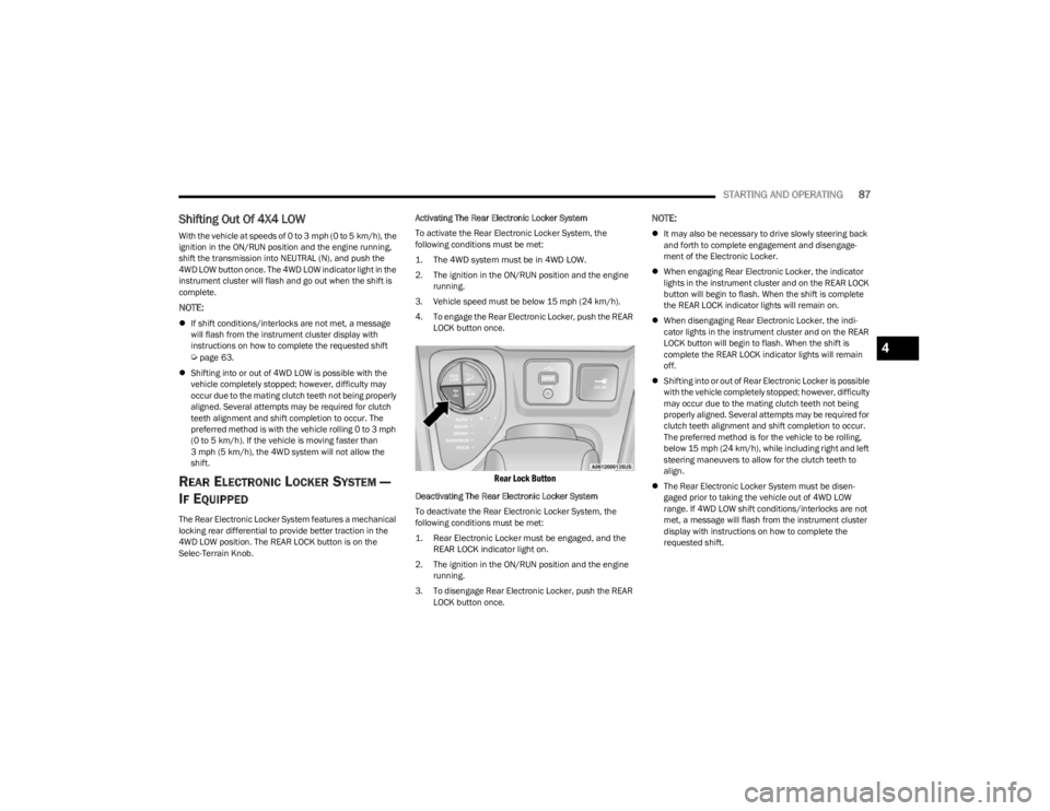
4WD LOW position. The REAR LOCK button is on the
Selec-Terrain Knob. Activating The Rear Electronic Locker System
To activate the Rear Electronic Locker System, the
following conditions must be met:
1. The 4WD system must be in 4WD LOW.
2. The ignition in the ON/RUN position and the engine
running.
3. Vehicle speed must be below 15 mph (24 km/h). 4. To engage the Rear Electronic Locker, push the REAR LOCK button once.
Rear Lock Button
Deactivating The Rear Electronic Locker System
To deactivate the Rear Electronic Locker System, the
following conditions must be met:
1. Rear Electronic Locker must be engaged, and the REAR LOCK indicator light on.
2. The ignition in the ON/RUN position and the engine running.
3. To disengage Rear Electronic Locker, push the REAR LOCK button once.
NOTE:
It may also be necessary to drive slowly steering back
and forth to complete engagement and disengage -
ment of the Electronic Locker.
When engaging Rear Electronic Locker, the indicator
lights in the instrument cluster and on the REAR LOCK
button will begin to flash. When the shift is complete
the REAR LOCK indicator lights will remain on.
When disengaging Rear Electronic Locker, the indi -
cator lights in the instrument cluster and on the REAR
LOCK button will begin to flash. When the shift is
complete the REAR LOCK indicator lights will remain
off.
Shifting into or out of Rear Electronic Locker is possible
with the vehicle completely stopped; however, difficulty
may occur due to the mating clutch teeth not being
properly aligned. Several attempts may be required for
clutch teeth alignment and shift completion to occur.
The preferred method is for the vehicle to be rolling,
below 15 mph (24 km/h), while including right and left
steering maneuvers to allow for the clutch teeth to
align.
The Rear Electronic Locker System must be disen -
gaged prior to taking the vehicle out of 4WD LOW
range. If 4WD LOW shift conditions/interlocks are not
met, a message will flash from the instrument cluster
display with instructions on how to complete the
requested shift.
4
23_KL_OM_EN_USC_t.book Page 87
Page 189 of 276
SAFETY187
(Continued)
(Continued)
SAFETY CHECKS YOU SHOULD MAKE
I
NSIDE THE VEHICLE
Seat Belts
Inspect the seat belt system periodically, checking for
cuts, frays, and loose parts. Damaged parts must be
replaced immediately. Do not disassemble or modify the
system.
If your vehicle is involved in a collision, or if you have
questions regarding seat belt or retractor conditions, take
your vehicle to an authorized FCA dealer or authorized FCA
Certified Collision Care Program facility for inspection.
Air Bag Warning Light
The Air Bag Warning Light will turn on for four to
eight seconds as a bulb check when the
ignition switch is first placed in the ON/RUN
position. If the light is either not on during
starting, stays on, or turns on while driving, have the
system inspected at an authorized dealer as soon as
possible. After the bulb check, this light will illuminate with
a single chime when a fault with the Air Bag System has
been detected. It will stay on until the fault is removed. If
the light comes on intermittently or remains on while
driving, have an authorized dealer service the vehicle
immediately.
See
Úpage 159 for further information.
Defroster
Check operation by selecting the defrost mode and place
the blower control on high speed. You should be able to feel
the air directed against the windshield. See an authorized
dealer for service if your defroster is inoperable.
Floor Mat Safety Information
Always use floor mats designed to fit your vehicle. Only use
a floor mat that does not interfere with the operation of the
accelerator, brake or clutch pedals. Only use a floor mat
that is securely attached using the floor mat fasteners so
it cannot slip out of position and interfere with the
accelerator, brake or clutch pedals or impair safe
operation of your vehicle in other ways.
WARNING!
An improperly attached, damaged, folded, or stacked
floor mat, or damaged floor mat fasteners may cause
your floor mat to interfere with the accelerator, brake, or
clutch pedals and cause a loss of vehicle control. To
prevent SERIOUS INJURY or DEATH:
ALWAYS securely attach your floor mat
using the floor mat fasteners. DO NOT install
your floor mat upside down or turn your floor
mat over. Lightly pull to confirm mat is
secured using the floor mat fasteners on a regular basis.
ALWAYS REMOVE THE EXISTING FLOOR
MAT FROM THE VEHICLE before installing
any other floor mat. NEVER install or stack an
additional floor mat on top of an existing floor
mat.
ONLY install floor mats designed to fit your vehicle.
NEVER install a floor mat that cannot be properly
attached and secured to your vehicle. If a floor mat
needs to be replaced, only use a FCA approved floor
mat for the specific make, model, and year of your
vehicle.
ONLY use the driver’s side floor mat on the driver’s
side floor area. To check for interference, with the
vehicle properly parked with the engine off, fully
depress the accelerator, the brake, and the clutch
pedal (if present) to check for interference. If your
floor mat interferes with the operation of any pedal,
or is not secure to the floor, remove the floor mat
from the vehicle and place the floor mat in your
trunk.
ONLY use the passenger’s side floor mat on the
passenger’s side floor area.
ALWAYS make sure objects cannot fall or slide into
the driver’s side floor area when the vehicle is
moving. Objects can become trapped under acceler -
ator, brake, or clutch pedals and could cause a loss
of vehicle control.
NEVER place any objects under the floor mat (e.g.,
towels, keys, etc.). These objects could change the
position of the floor mat and may cause interference
with the accelerator, brake, or clutch pedals.
WARNING!
6
23_KL_OM_EN_USC_t.book Page 187
Page 190 of 276
188SAFETY
PERIODIC SAFETY CHECKS YOU SHOULD
M
AKE OUTSIDE THE VEHICLE
Tires
Examine tires for excessive tread wear and uneven wear
patterns. Check for stones, nails, glass, or other objects
lodged in the tread or sidewall. Inspect the tread for cuts
and cracks. Inspect sidewalls for cuts, cracks, and bulges.
Check the lug nut/bolt torque for tightness. Check the
tires (including spare) for proper cold inflation pressure.
Lights
Have someone observe the operation of brake lights and
exterior lights while you work the controls. Check turn signal
and high beam indicator lights on the instrument panel.
Door Latches
Check for proper closing, latching, and locking.
Fluid Leaks
Check the area under the vehicle after overnight parking
for fuel, coolant, oil, or other fluid leaks. Also, if gasoline
fumes are detected or if fuel or brake fluid leaks are
suspected, the cause should be located and corrected
immediately.
EXHAUST GAS
The best protection against carbon monoxide entry into
the vehicle body is a properly maintained engine exhaust
system. Whenever a change is noticed in the sound of the exhaust
system, when exhaust fumes can be detected inside the
vehicle, or when the underside or rear of the vehicle is
damaged, have an authorized dealer inspect the complete
exhaust system and adjacent body areas for broken,
damaged, deteriorated, or mispositioned parts. Open
seams or loose connections could permit exhaust fumes
to seep into the passenger compartment. In addition,
inspect the exhaust system each time the vehicle is raised
for lubrication or oil change. Replace as required.
CARBON MONOXIDE WARNINGS
If the vehicle carpet has been removed and
re-installed, always properly attach carpet to the floor
and check the floor mat fasteners are secure to the
vehicle carpet. Fully depress each pedal to check for
interference with the accelerator, brake, or clutch
pedals then re-install the floor mats.
It is recommended to only use mild soap and water
to clean your floor mats. After cleaning, always check
your floor mat has been properly installed and is
secured to your vehicle using the floor mat fasteners
by lightly pulling mat.
WARNING!
WARNING!
Exhaust gases can injure or kill. They contain carbon
monoxide (CO), which is colorless and odorless.
Breathing it can make you unconscious and can
eventually poison you. To avoid breathing (CO), follow
these safety tips:
Do not run the engine in a closed garage or in
confined areas any longer than needed to move your
vehicle in or out of the area.
If you are required to drive with the trunk/liftgate/
rear doors open, make sure that all windows are
closed and the climate control BLOWER switch is set
at high speed. DO NOT use the recirculation mode.
If it is necessary to sit in a parked vehicle with the
engine running, adjust your heating or cooling
controls to force outside air into the vehicle. Set the
blower at high speed.
WARNING!
Carbon monoxide (CO) in exhaust gases is deadly.
Follow the precautions below to prevent carbon
monoxide poisoning:
Do not inhale exhaust gases. They contain carbon
monoxide, a colorless and odorless gas, which can
kill. Never run the engine in a closed area, such as a
garage, and never sit in a parked vehicle with the
engine running for an extended period. If the vehicle
is stopped in an open area with the engine running
for more than a short period, adjust the ventilation
system to force fresh, outside air into the vehicle.
Guard against carbon monoxide with proper mainte -
nance. Have the exhaust system inspected every
time the vehicle is raised. Have any abnormal condi -
tions repaired promptly. Until repaired, drive with all
side windows fully open.
23_KL_OM_EN_USC_t.book Page 188
Page 206 of 276
204IN CASE OF EMERGENCY
6. Move the gear selector to the NEUTRAL (N) position.
7. The vehicle may then be started in NEUTRAL (N).
8. Reinstall the gear selector boot.
FREEING A STUCK VEHICLE
If your vehicle becomes stuck in mud, sand or snow, it can
often be moved using a rocking motion. Turn the steering
wheel right and left to clear the area around the front
wheels. Push and hold the lock button on the gear
selector. Then shift back and forth between DRIVE (D) and
REVERSE (R), while gently pressing the accelerator.
NOTE:Shifts between DRIVE (D) and REVERSE (R) can only be
achieved at wheel speeds of 5 mph (8 km/h) or less.
Whenever the transmission remains in NEUTRAL (N) for
more than two seconds, you must press the brake pedal
to engage DRIVE (D) or REVERSE (R). Use the least amount of accelerator pedal pressure that
will maintain the rocking motion without spinning the
wheels or racing the engine.NOTE:Push the ESC OFF button (if necessary), to place the Elec
-
tronic Stability Control (ESC) system in “Partial Off” mode,
before rocking the vehicle
Úpage 145. Once the vehicle
has been freed, push the ESC OFF button again to restore
“ESC On” mode.
WARNING!
Fast spinning tires can be dangerous. Forces generated
by excessive wheel speeds may cause damage, or even
failure, of the axle and tires. A tire could explode and
injure someone. Do not spin your vehicle's wheels
faster than 30 mph (48 km/h) or for longer than 30
seconds continuously without stopping when you are
stuck and do not let anyone near a spinning wheel, no
matter what the speed.
CAUTION!
Racing the engine or spinning the wheels may lead to
transmission overheating and failure. Allow the
engine to idle with the transmission in NEUTRAL for
at least one minute after every five rocking-motion
cycles. This will minimize overheating and reduce the
risk of clutch or transmission failure during
prolonged efforts to free a stuck vehicle.
When “rocking” a stuck vehicle by shifting between
DRIVE and REVERSE, do not spin the wheels faster
than 15 mph (24 km/h), or drivetrain damage may
result.
Revving the engine or spinning the wheels too fast
may lead to transmission overheating and failure. It
can also damage the tires. Do not spin the wheels
above 30 mph (48 km/h) while in gear (no transmis -
sion shifting occurring).
23_KL_OM_EN_USC_t.book Page 204
Page 230 of 276
228SERVICING AND MAINTENANCE
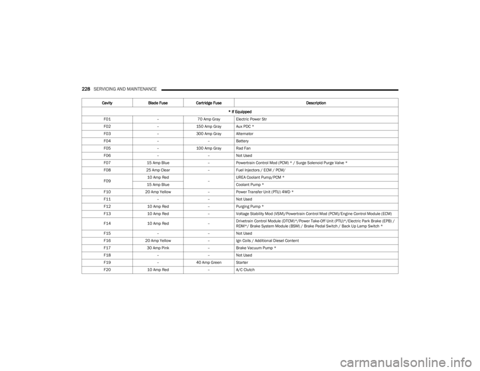
CavityBlade Fuse Cartridge Fuse Description
* If Equipped
F01 –70 Amp Gray Electric Power Str
F02 –150 Amp Gray Aux PDC *
F03 –300 Amp Gray Alternator
F04 ––Battery
F05 –100 Amp Gray Rad Fan
F06 ––Not Used
F07 15 Amp Blue –Powertrain Control Mod (PCM) * / Surge Solenoid Purge Valve *
F08 25 Amp Clear –Fuel Injectors / ECM / PCM/
F09 10 Amp Red
–UREA Coolant Pump/PCM *
15 Amp Blue Coolant Pump *
F10 20 Amp Yellow –Power Transfer Unit (PTU) 4WD *
F11 ––Not Used
F12 10 Amp Red –Purging Pump *
F13 10 Amp Red –Voltage Stability Mod (VSM)/Powertrain Control Mod (PCM)/Engine Control Module (ECM)
F14 10 Amp Red –Drivetrain Control Module (DTCM)*/Power Take-Off Unit (PTU)*/Electric Park Brake (EPB) /
RDM*/ Brake System Module (BSM) / Brake Pedal Switch / Back Up Lamp Switch *
F15 ––Not Used
F16 20 Amp Yellow –Ign Coils / Additional Diesel Content
F17 30 Amp Pink –Brake Vacuum Pump *
F18 ––Not Used
F19 –40 Amp Green Starter
F20 10 Amp Red –A/C Clutch
23_KL_OM_EN_USC_t.book Page 228
Page 271 of 276

269
Storing Your Vehicle ..................................................... 250
Stuck, Freeing .............................................................. 204
Sun Roof ...................................................................54
, 56
Closing ........................................................................54
Opening ...................................................................... 54
Sun Visor Extension ........................................................34
Sunshade Operation ....................................................... 54
Supplemental Restraint System – Air Bag ................. 167
Sway Control, Trailer .................................................... 150
Symbol Glossary ................................................................ 9
Synthetic Engine Oil ..................................................... 215
System, Remote Starting ................................................18
TTemperature Control, Automatic (ATC) ..........................48
Tie Down Hooks, Cargo...................................................59 Time Delay Headlight ....................................................................41
Tire And Loading Information Placard ........................ 238
Tire Markings................................................................ 235
Tire Safety Information ................................................ 235
Tire Service Kit ................................. 196
, 197, 199, 200
Tires .................................................. 188, 241, 244, 249
Aging (Life Of Tires)................................................. 243 Air Pressure ............................................................. 241
Chains...................................................................... 246Changing ................................................................. 191
Compact Spare ....................................................... 245
General Information ...................................... 241
, 244
High Speed .............................................................. 242
Inflation Pressure ................................................... 241
Jacking..................................................................... 191
Life Of Tires ............................................................. 243
Load Capacity................................................. 238
, 239 Pressure Monitoring System (TPMS) ..............72
, 155
Quality Grading ........................................................ 249
Radial ....................................................................... 242
Replacement ...........................................................243
Rotation....................................................................248 Safety ............................................................. 235
, 241
Sizes ......................................................................... 236
Snow Tires................................................................ 244
Spare Tires..................................................... 244
, 245
Spinning ...................................................................242 Trailer Towing .......................................................... 118
Tread Wear Indicators ............................................. 243Wheel Nut Torque....................................................253
To Open Hood ................................................................. 56
Tongue Weight/Trailer Weight ........................... 115
, 117
Torque Converter Clutch ................................................ 85
Tow Hooks Emergency ............................................................... 206
Towing ........................................................ 114
, 116, 205
Disabled Vehicle ...................................................... 205
Recreational ............................................................120
Towing Behind A Motorhome ....................................... 120
Traction Control ............................................................150
Trailer Sway Control (TSC) ............................................150
Trailer Towing ................................................................ 114 Frontal Area ............................................................. 115
Hitches .....................................................................116
Minimum Requirements ......................................... 117
Tips ...........................................................................119Trailer And Tongue Weight............................ 116
, 117
Weight Carrying Hitch.............................................. 115 Weight Distributing Hitch ........................................ 115
Wiring ....................................................................... 118
Trailer Towing Guide ..................................................... 116
Trailer Weight ................................................................ 116 Transaxle
Automatic .................................................................. 81
Operation ................................................................... 81
Transmission .................................................................. 81 Automatic ......................................................... 81
, 225
Maintenance ........................................................... 225
Transporting Pets ......................................................... 186
Tread Wear Indicators.................................................. 243
Turn Signals ...................................................... 39
, 42, 74
UUconnect Uconnect Settings ............................................ 19, 126
Uconnect Settings Customer Programmable Features .................. 19
, 22
Passive Entry Programming ..................................... 22
Uniform Tire Quality Grades ........................................ 249
Universal Garage Door Opener (HomeLink®) .............. 35
Universal Garage Door Opener (HomeLink®) —
If Equipped
S
............................................................... 35
Untwisting Procedure, Seat Belt.................................. 162
USB.................................................................................. 50
VVanity Mirrors ................................................................. 34
Vehicle Identification Number (VIN) ............................ 253
Vehicle Loading ...................................................113
, 239
Vehicle Maintenance ................................................... 215
Vehicle Modifications/Alterations ....................................8
Vehicle Settings ............................................................ 126
Vehicle Storage...................................................... 48
, 250
Voice Command ............................................................. 25
Voice Recognition System (VR) ..................................... 2511
23_KL_OM_EN_USC_t.book Page 269