sensor JEEP CHEROKEE 2023 Owners Manual
[x] Cancel search | Manufacturer: JEEP, Model Year: 2023, Model line: CHEROKEE, Model: JEEP CHEROKEE 2023Pages: 276, PDF Size: 12.55 MB
Page 6 of 276
4
CRUISE CONTROL SYSTEMS — IF EQUIPPED .................90
Cruise Control.............................................................. 90
Adaptive Cruise Control (ACC) ................................... 92
PARKSENSE FRONT/REAR PARK ASSIST
SYSTEM — IF EQUIPPED.....................................................99 ParkSense Sensors ................................................... 100
ParkSense Display .................................................... 100
ParkSense Warning Display ..................................... 103
Enabling And Disabling ParkSense.......................... 103Service The ParkSense Park Assist System ............ 103Cleaning The ParkSense System ............................. 103
ParkSense System Usage Precautions ................... 103Side Distance Warning System ................................ 104
PARKSENSE ACTIVE PARK ASSIST
SYSTEM — IF EQUIPPED.................................................. 106 Enabling And Disabling The ParkSense Active
Park Assist System.................................................... 106
Parallel/Perpendicular Parking Space Assistance
Operation ................................................................... 107
Exiting The Parking Space ........................................ 109
LANESENSE — IF EQUIPPED .......................................... 109 LaneSense Operation ............................................... 109Turning LaneSense On Or Off................................... 110
LaneSense Warning Message.................................. 110Changing LaneSense Settings ................................. 112
PARKVIEW REAR BACK UP CAMERA ........................... 112
REFUELING THE VEHICLE .............................................. 113
VEHICLE LOADING ........................................................... 113 Certification Label ..................................................... 113 TRAILER TOWING ............................................................ 114
Common Towing Definitions .................................... 114Trailer Hitch Classification ....................................... 116
Trailer Towing Weights (Maximum Trailer Weight
Ratings) ..................................................................... 116
Trailer And Tongue Weight ...................................... 117
Towing Requirements............................................... 117
Towing Tips ............................................................... 119
RECREATIONAL TOWING (BEHIND MOTORHOME) .... 120 Towing This Vehicle Behind Another Vehicle .......... 120
Recreational Towing — Front-Wheel Drive (FWD)
Models ....................................................................... 121Recreational Towing — 4x4 Models With 1-Speed
Power Transfer Unit .................................................. 121Recreational Towing — 4x4 Models With 2-Speed
Power Transfer Unit .................................................. 121
DRIVING TIPS ................................................................... 123 On-Road Driving Tips ................................................ 123
Off-Road Driving Tips ................................................ 123
MULTIMEDIA
UCONNECT SYSTEMS ..................................................... 126
CYBERSECURITY ............................................................. 126
UCONNECT SETTINGS ..................................................... 126 Customer Programmable Features ......................... 127
STEERING WHEEL AUDIO CONTROLS —
IF EQUIPPED ..................................................................... 140 Radio Operation ........................................................ 140Media Mode .............................................................. 140
RADIO OPERATION AND MOBILE PHONES.................. 140 Regulatory And Safety Information.......................... 140 OFF-ROAD PAGES — IF EQUIPPED .................................141
Off-Road Pages Status Bar ...................................... 141Drivetrain .................................................................. 141
Pitch & Roll ............................................................... 142
Accessory Gauges .................................................... 142
Selec-Terrain — If Equipped ..................................... 142
SAFETY
SAFETY FEATURES ...........................................................143 Anti-Lock Brake System (ABS) ................................. 143
Electronic Brake Control (EBC) System ................... 143
AUXILIARY DRIVING SYSTEMS .......................................150 Blind Spot Monitoring (BSM) — If Equipped ............ 150
Forward Collision Warning (FCW) With
Mitigation — If Equipped ........................................... 154
Tire Pressure Monitoring System (TPMS) ................ 155
OCCUPANT RESTRAINT SYSTEMS ................................159 Occupant Restraint Systems Features ................... 159
Important Safety Precautions................................... 159
Seat Belt Systems .................................................... 159
Supplemental Restraint Systems (SRS) .................. 166Child Restraints ......................................................... 176
SAFETY TIPS......................................................................186 Transporting Passengers .......................................... 186
Transporting Pets ...................................................... 186Connected Vehicles................................................... 186
Safety Checks You Should Make Inside The
Vehicle ....................................................................... 187
Periodic Safety Checks You Should Make
Outside The Vehicle .................................................. 188
Exhaust Gas ............................................................... 188
Carbon Monoxide Warnings ..................................... 188
23_KL_OM_EN_USC_t.book Page 4
Page 27 of 276
GETTING TO KNOW YOUR VEHICLE25
HEATED STEERING WHEEL —
I
F EQUIPPED
The steering wheel contains a heating element
that helps warm your hands in cold weather.
The heated steering wheel has only one
temperature setting. Once the heated steering
wheel has been turned on, a sensor will monitor the
temperature of the steering wheel and adjust the power
level to maintain an optimum heat level.
The heated steering wheel control button is located within
the Uconnect system. You can gain access to the control
button through the climate screen or the controls screen.
Press the heated steering wheel button once to turn
the heating element on.
Press the heated steering wheel button a second time
to turn the heating element off.
NOTE:The engine must be running for the heated steering wheel
to operate. For information on use with the Remote Start system, see
Úpage 19.
UCONNECT VOICE RECOGNITION
INTRODUCING VOICE RECOGNITION
Start using Uconnect Voice Recognition with these helpful
quick tips. This section provides Voice Commands and tips
you need to know to control your vehicle’s Voice
Recognition (VR) system.
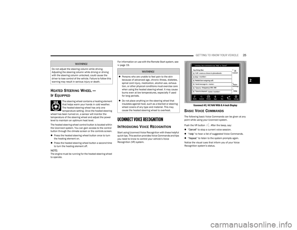
Uconnect 4C/4C NAV With 8.4-inch Display
BASIC VOICE COMMANDS
The following basic Voice Commands can be given at any
point while using your Uconnect system.
Push the VR button . After the beep, say:
“Cancel ” to stop a current voice session.
“Help ” to hear a list of suggested Voice Commands.
“Repeat ” to listen to the system prompts again.
Notice the visual cues that inform you of your Voice
Recognition system’s status.
WARNING!
Do not adjust the steering column while driving.
Adjusting the steering column while driving or driving
with the steering column unlocked, could cause the
driver to lose control of the vehicle. Failure to follow this
warning may result in serious injury or death.WARNING!
Persons who are unable to feel pain to the skin
because of advanced age, chronic illness, diabetes,
spinal cord injury, medication, alcohol use, exhaus -
tion, or other physical conditions must exercise care
when using the heated steering wheel. It may cause
burns even at low temperatures, especially if used
for long periods.
Do not place anything on the steering wheel that
insulates against heat, such as a blanket or steering
wheel covers of any type and material. This may
cause the heated steering wheel to overheat.
2
23_KL_OM_EN_USC_t.book Page 25
Page 60 of 276
58GETTING TO KNOW YOUR VEHICLE
TO LOCK/CLOSE THE LIFTGATE
There are several different ways to close the liftgate:
Manually by grabbing the liftgate closing handle and
pulling in a downward motion to close the liftgate.
Release the handle when the liftgate takes over the
closing effort.
Key fob liftgate button (if equipped)
Hands-Free (if equipped)
Liftgate instrument panel button (if equipped)
Power Liftgate button on the pillar in the cargo area (if
equipped)
With a valid Passive Entry key fob within 5 ft (1.5 m) of the liftgate, pushing the Keyless Enter ‘n Go™ — Passive Entry
lock/push button located to the left of the Back Up
Camera will lock the vehicle only.
The power liftgate may be closed by pushing the rear
power liftgate button, located in the upper left trim in the
liftgate opening. Pushing the button will only close the
liftgate. This button cannot be used to open the liftgate.
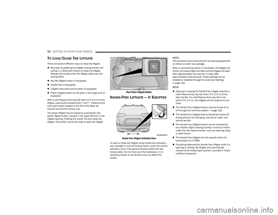
Rear Power Liftgate Button
HANDS-FREE LIFTGATE — IF EQUIPPED
Hands-Free Liftgate Activation Zone
To open or close the liftgate using hands-free activation,
use a straight in and out kicking motion under the vehicle
activation zone in the general location below the rear
license plate. Do not move your foot sideways or in a
sweeping motion or the sensors may not detect the
motion.
NOTE:The activation zone is the same for vehicles equipped with
or without a trailer tow package.
When a valid kicking motion is completed, the liftgate will
chime, the hazard lights will flash and the liftgate will open
after approximately one second, or close after
approximately three seconds. These settings can be
enabled or disabled through the Uconnect Settings
Úpage 126.
NOTE:
Opening or closing the Hands-Free Liftgate requires a
valid Passive Entry key fob within 5 ft (1.5 m) of the
door handle. If a valid Passive Entry key fob is not
within 5 ft (1.5 m), the liftgate will not respond to any
kicks.
The Hands-Free Liftgate feature may be turned on or
off through the Uconnect system
Úpage 126.
The Hands-Free Liftgate feature should be turned off
during jacking, tire changing, manual car wash, and
vehicle service.
The Hands-Free Liftgate feature can be activated by
any metallic object making a similar in-and-out motion
under the rear fascia/bumper, such as cleaning using
a metal broom.
The Hands-Free Liftgate will only operate when the
transmission is in PARK.
If anything obstructs the Hands-Free Liftgate while it is
opening or closing, the liftgate will automatically
reverse to the closed/open position, provided it meets
sufficient resistance.
23_KL_OM_EN_USC_t.book Page 58
Page 61 of 276
GETTING TO KNOW YOUR VEHICLE59
There are pinch sensors attached to the side of the lift -
gate opening. Light pressure anywhere along these
strips will cause the liftgate to return to the open posi -
tion.
If the power liftgate encounters multiple obstructions
within the same cycle, the system will automatically
stop. If this occurs, the liftgate must be operated manu -
ally.
The power liftgate will release, but not power open, in
temperatures below −12°F (−24°C). Be sure to
remove any buildup of snow or ice from the liftgate
before opening the liftgate.
If the liftgate is left open for an extended period of time,
the liftgate may need to be closed manually to reset
power liftgate functionality.
Gas props support the liftgate in the open position.
However, because the gas pressure drops with
temperature, it may be necessary to assist the props when
opening the liftgate in cold weather.NOTE:Allow the power system to open the liftgate. Manually
pushing or pulling the liftgate may activate the liftgate
obstacle detection feature and stop the power operation
or reverse its direction.
CARGO AREA FEATURES
Cargo Load Floor
The cargo load floor system has a load capacity of 300 lb
(136 kg).
To provide additional storage area, each rear seat can be
folded flat. This allows for extended cargo space and still
maintains some rear seating room
Úpage 28.
Cargo Tie-Down Hooks And Loops
The tie-downs located on the cargo area floor should be
used to secure loads safely when the vehicle is moving.
Cargo tie-down loops are located on the trim panels.
WARNING!
Driving with the liftgate open can allow poisonous
exhaust gases into your vehicle. You and your
passengers could be injured by these fumes. Keep
the liftgate closed when you are operating the
vehicle.
If you are required to drive with the liftgate open,
make sure that all windows are closed, and the
climate control blower switch is set at high speed. Do
not use the recirculation mode.
WARNING!
During power operation, personal injury or cargo
damage may occur. Ensure the liftgate travel path is
clear. Make sure the liftgate is closed and latched
before driving away.
WARNING!
Cargo tie-downs are not safe anchors for a child seat
tether strap. In a sudden stop or accident, a tie-down
could pull loose and allow the child seat to come
loose. A child could be badly injured. Use only the
anchors provided for child seat tethers.
To help protect against personal injury, passengers
should not be seated in the rear cargo area. The rear
cargo space is intended for load carrying purposes
only, not for passengers, who should sit in seats and
use seat belts.
The weight and position of cargo and passengers can
change the vehicle center of gravity and vehicle
handling. To avoid loss of control resulting in personal
injury, follow these guidelines for loading your vehicle:
Do not carry loads that exceed the load limits
described on the label attached to the left door or left
door center pillar.
Always place cargo evenly on the cargo floor. Put
heavier objects as low and as far forward as possible.
Place as much cargo as possible in front of the rear
axle. Too much weight or improperly placed weight
over or behind the rear axle can cause the vehicle to
sway.
Do not pile luggage or cargo higher than the top of
the seatback. This could impair visibility or become a
dangerous projectile in a sudden stop or accident.
2
23_KL_OM_EN_USC_t.book Page 59
Page 69 of 276
GETTING TO KNOW YOUR INSTRUMENT PANEL67
INSTRUMENT CLUSTER DISPLAY
S
ELECTABLE ITEMS
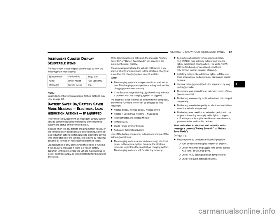
The instrument cluster display can be used to view the
following main menu items:
NOTE:Depending on the vehicles options, feature settings may
vary Úpage 63.
BATTERY SAVER ON/BATTERY SAVER
M
ODE MESSAGE — ELECTRICAL LOAD
R
EDUCTION ACTIONS — IF EQUIPPED
This vehicle is equipped with an Intelligent Battery Sensor
(IBS) to perform additional monitoring of the electrical
system and status of the vehicle battery.
In cases when the IBS detects charging system failure, or
the vehicle battery conditions are deteriorating, electrical
load reduction actions will take place to extend the driving
time and distance of the vehicle. This is done by reducing
power to or turning off non-essential electrical loads.
Load reduction is only active when the engine is running.
It will display a message if there is a risk of battery
depletion to the point where the vehicle may stall due to
lack of electrical supply, or will not restart after the current
drive cycle. When load reduction is activated, the message “Battery
Saver On” or “Battery Saver Mode” will appear in the
instrument cluster display.
These messages indicate the vehicle battery has a low
state of charge and continues to lose electrical charge at
a rate that the charging system cannot sustain.
NOTE:
The charging system is independent from load reduc -
tion. The charging system performs a diagnostic on the
charging system continuously.
If the Battery Charge Warning Light is on it may indicate
a problem with the charging system
Úpage 69.
The electrical loads that may be switched off (if equipped),
and vehicle functions which can be effected by load
reduction:
Heated Seats / Vented Seats / Heated Wheel
Heated / Cooled Cup Holders — If Equipped
Rear Defroster And Heated Mirrors
HVAC System
150W Power Inverter System
Audio and Telematics System
Loss of the battery charge may indicate one or more of the
following conditions:
The charging system cannot deliver enough electrical
power to the vehicle system because the electrical
loads are larger than the capability of charging system.
The charging system is still functioning properly.
Turning on all possible vehicle electrical loads
(e.g. HVAC to max settings, exterior and interior
lights, overloaded power outlets +12 Volts, 150W,
USB ports) during certain driving conditions
(city driving, towing, frequent stopping).
Installing options like additional lights, upfitter elec -
trical accessories, audio systems, alarms and similar
devices.
Unusual driving cycles (short trips separated by long
parking periods).
The vehicle was parked for an extended period of time
(weeks, months).
The battery was recently replaced and was not charged
completely.
The battery was discharged by an electrical load left on
when the vehicle was parked.
The battery was used for an extended period with the
engine not running to supply radio, lights, chargers,
+12 Volts portable appliances like vacuum cleaner’s,
game consoles and similar devices.
What to do when an electrical load reduction action
message is present (“Battery Saver On” or “Battery
Saver Mode”)
During a trip:
Reduce power to unnecessary loads if possible:
Turn off redundant lights (interior or exterior).
Check what may be plugged in to power outlets
+12 Volts, 150W, USB ports.
Check HVAC settings (blower, temperature).
Check the audio settings (volume).
Speedometer Vehicle Info Stop/Start
Audio
Driver Assist Fuel Economy
Messages Screen Setup Trip
3
23_KL_OM_EN_USC_t.book Page 67
Page 75 of 276
GETTING TO KNOW YOUR INSTRUMENT PANEL73
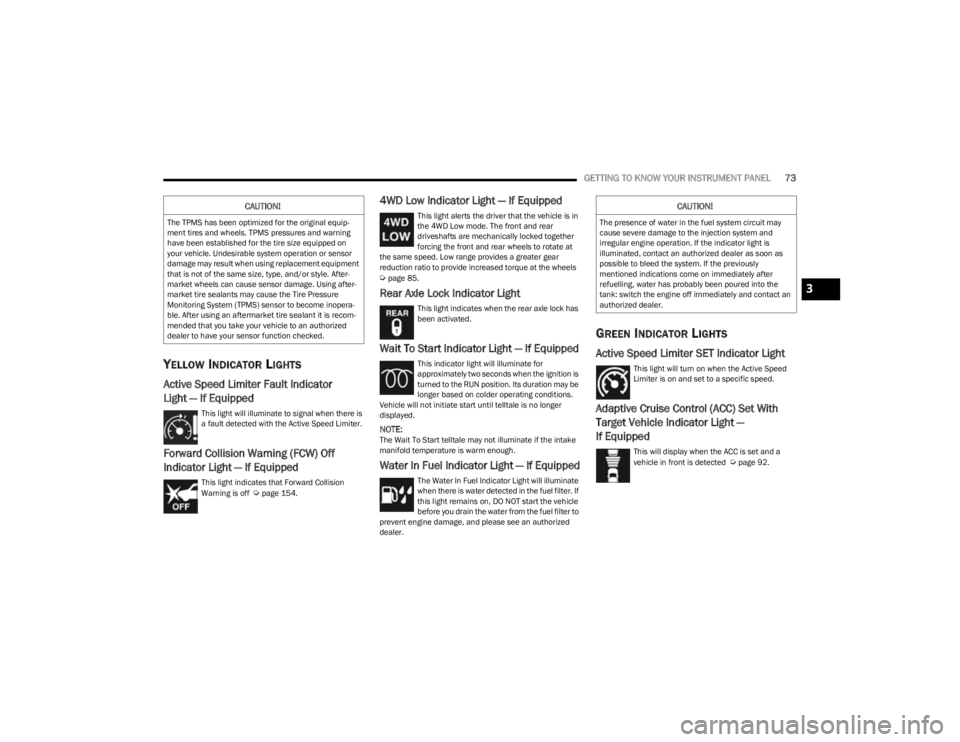
YELLOW INDICATOR LIGHTS
Active Speed Limiter Fault Indicator
Light — If Equipped
This light will illuminate to signal when there is
a fault detected with the Active Speed Limiter.
Forward Collision Warning (FCW) Off
Indicator Light — If Equipped
This light indicates that Forward Collision
Warning is off Úpage 154.
4WD Low Indicator Light — If Equipped
This light alerts the driver that the vehicle is in
the 4WD Low mode. The front and rear
driveshafts are mechanically locked together
forcing the front and rear wheels to rotate at
the same speed. Low range provides a greater gear
reduction ratio to provide increased torque at the wheels
Úpage 85.
Rear Axle Lock Indicator Light
This light indicates when the rear axle lock has
been activated.
Wait To Start Indicator Light — If Equipped
This indicator light will illuminate for
approximately two seconds when the ignition is
turned to the RUN position. Its duration may be
longer based on colder operating conditions.
Vehicle will not initiate start until telltale is no longer
displayed.
NOTE:The Wait To Start telltale may not illuminate if the intake
manifold temperature is warm enough.
Water In Fuel Indicator Light — If Equipped
The Water In Fuel Indicator Light will illuminate
when there is water detected in the fuel filter. If
this light remains on, DO NOT start the vehicle
before you drain the water from the fuel filter to
prevent engine damage, and please see an authorized
dealer.
GREEN INDICATOR LIGHTS
Active Speed Limiter SET Indicator Light
This light will turn on when the Active Speed
Limiter is on and set to a specific speed.
Adaptive Cruise Control (ACC) Set With
Target Vehicle Indicator Light —
If Equipped
This will display when the ACC is set and a
vehicle in front is detected Úpage 92.
CAUTION!
The TPMS has been optimized for the original equip -
ment tires and wheels. TPMS pressures and warning
have been established for the tire size equipped on
your vehicle. Undesirable system operation or sensor
damage may result when using replacement equipment
that is not of the same size, type, and/or style. After -
market wheels can cause sensor damage. Using after -
market tire sealants may cause the Tire Pressure
Monitoring System (TPMS) sensor to become inopera -
ble. After using an aftermarket tire sealant it is recom -
mended that you take your vehicle to an authorized
dealer to have your sensor function checked.
CAUTION!
The presence of water in the fuel system circuit may
cause severe damage to the injection system and
irregular engine operation. If the indicator light is
illuminated, contact an authorized dealer as soon as
possible to bleed the system. If the previously
mentioned indications come on immediately after
refuelling, water has probably been poured into the
tank: switch the engine off immediately and contact an
authorized dealer.
3
23_KL_OM_EN_USC_t.book Page 73
Page 94 of 276
92STARTING AND OPERATING
(Continued)
To Deactivate
A tap on the brake pedal, pushing the CANC button, or
normal brake pressure will deactivate the Cruise Control
system without erasing the set speed from memory.
The following conditions will also deactivate the Cruise
Control without erasing the set speed from memory:
Vehicle parking brake is applied
Stability event occurs
Gear selector is moved out of DRIVE
Engine overspeed occurs
Pushing the on/off button or placing the ignition in the OFF
position, will erase the set speed from memory.
ADAPTIVE CRUISE CONTROL (ACC)
Adaptive Cruise Control (ACC) increases the driving
convenience provided by Cruise Control while traveling on
highways and major roadways. However, it is not a safety
system and not designed to prevent collisions. The Cruise
Control function performs differently
Úpage 90.
ACC will allow you to keep Cruise Control engaged in light
to moderate traffic conditions without the constant need
to reset your Cruise Control. ACC utilizes a radar sensor
and a forward facing camera designed to detect a vehicle
directly ahead of you.
NOTE:
If the ACC sensor detects a vehicle ahead, ACC will
apply limited braking or acceleration (not to exceed the
original set speed) automatically to maintain a preset
following distance, while matching the speed of the
vehicle ahead.
Any chassis/suspension or tire size modifications to
the vehicle will affect the performance of the Adaptive
Cruise Control and Forward Collision Warning system.
Fixed Speed Cruise Control will not detect vehicles
directly ahead of you. Always be aware of the feature
selected
Úpage 262.
WARNING!
Adaptive Cruise Control (ACC) is a convenience
system. It is not a substitute for active driver involve -
ment. It is always the driver’s responsibility to be
attentive of road, traffic, and weather conditions,
vehicle speed, distance to the vehicle ahead and,
most importantly, brake operation to ensure safe
operation of the vehicle under all road conditions.
Your complete attention is always required while
driving to maintain safe control of your vehicle.
Failure to follow these warnings can result in a colli -
sion and death or serious personal injury.
The ACC system:
Does not react to pedestrians, oncoming vehi -
cles, and stationary objects (e.g., a stopped
vehicle in a traffic jam or a disabled vehicle).
Cannot take street, traffic, and weather condi -
tions into account, and may be limited upon
adverse sight distance conditions.
Does not always fully recognize complex driving
conditions, which can result in wrong or missing
distance warnings.
Will bring the vehicle to a complete stop and
hold the vehicle in the stop position for approxi -
mately three minutes when following a vehicle
ahead. If the vehicle ahead does not start
moving within three minutes, the parking brake
will be activated, and the ACC system will be
canceled.
You should switch off the ACC system:
When driving in fog, heavy rain, heavy snow,
sleet, heavy traffic, and complex driving situa-
tions (i.e., in highway construction zones).
When entering a turn lane or highway off-ramp;
when driving on roads that are winding, icy,
snow-covered, slippery, or have steep uphill or
downhill slopes.
When towing a trailer up or down steep slopes.
When circumstances do not allow safe driving at
a constant speed.
WARNING!
23_KL_OM_EN_USC_t.book Page 92
Page 98 of 276
96STARTING AND OPERATING
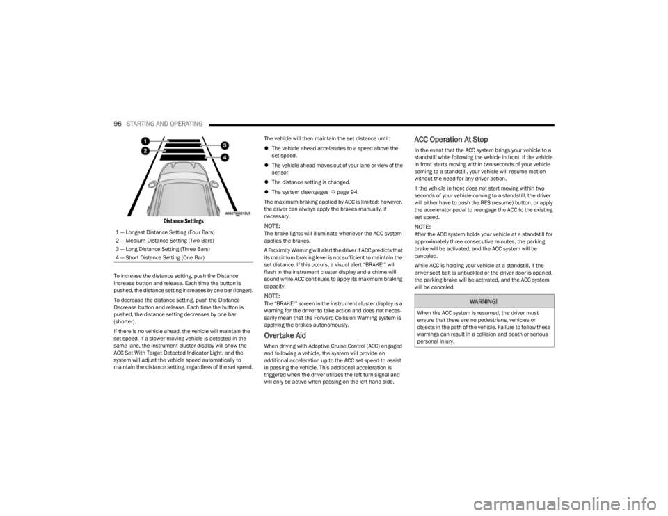
Distance Settings
To increase the distance setting, push the Distance
Increase button and release. Each time the button is
pushed, the distance setting increases by one bar (longer).
To decrease the distance setting, push the Distance
Decrease button and release. Each time the button is
pushed, the distance setting decreases by one bar
(shorter).
If there is no vehicle ahead, the vehicle will maintain the
set speed. If a slower moving vehicle is detected in the
same lane, the instrument cluster display will show the
ACC Set With Target Detected Indicator Light, and the
system will adjust the vehicle speed automatically to
maintain the distance setting, regardless of the set speed. The vehicle will then maintain the set distance until:
The vehicle ahead accelerates to a speed above the
set speed.
The vehicle ahead moves out of your lane or view of the
sensor.
The distance setting is changed.
The system disengages
Úpage 94.
The maximum braking applied by ACC is limited; however,
the driver can always apply the brakes manually, if
necessary.
NOTE:The brake lights will illuminate whenever the ACC system
applies the brakes.
A Proximity Warning will alert the driver if ACC predicts that
its maximum braking level is not sufficient to maintain the
set distance. If this occurs, a visual alert “BRAKE!” will
flash in the instrument cluster display and a chime will
sound while ACC continues to apply its maximum braking
capacity.
NOTE:The “BRAKE!” screen in the instrument cluster display is a
warning for the driver to take action and does not neces -
sarily mean that the Forward Collision Warning system is
applying the brakes autonomously.
Overtake Aid
When driving with Adaptive Cruise Control (ACC) engaged
and following a vehicle, the system will provide an
additional acceleration up to the ACC set speed to assist
in passing the vehicle. This additional acceleration is
triggered when the driver utilizes the left turn signal and
will only be active when passing on the left hand side.
ACC Operation At Stop
In the event that the ACC system brings your vehicle to a
standstill while following the vehicle in front, if the vehicle
in front starts moving within two seconds of your vehicle
coming to a standstill, your vehicle will resume motion
without the need for any driver action.
If the vehicle in front does not start moving within two
seconds of your vehicle coming to a standstill, the driver
will either have to push the RES (resume) button, or apply
the accelerator pedal to reengage the ACC to the existing
set speed.
NOTE:After the ACC system holds your vehicle at a standstill for
approximately three consecutive minutes, the parking
brake will be activated, and the ACC system will be
canceled.
While ACC is holding your vehicle at a standstill, if the
driver seat belt is unbuckled or the driver door is opened,
the parking brake will be activated, and the ACC system
will be canceled.
1 — Longest Distance Setting (Four Bars)
2 — Medium Distance Setting (Two Bars)
3 — Long Distance Setting (Three Bars)
4 — Short Distance Setting (One Bar)
WARNING!
When the ACC system is resumed, the driver must
ensure that there are no pedestrians, vehicles or
objects in the path of the vehicle. Failure to follow these
warnings can result in a collision and death or serious
personal injury.
23_KL_OM_EN_USC_t.book Page 96
Page 99 of 276
STARTING AND OPERATING97
Display Warnings And Maintenance
“WIPE FRONT RADAR SENSOR IN FRONT OF
VEHICLE” WARNING
The “ACC/FCW Unavailable Wipe Front Radar Sensor”
warning will display and a chime will sound when
conditions temporarily limit system performance.
This most often occurs at times of poor visibility, such as
in snow or heavy rain. The ACC system may also become
temporarily blinded due to obstructions, such as mud, dirt
or ice. In these cases, the instrument cluster display will
display this message and the system will deactivate.
This message can sometimes be displayed while driving in
highly reflective areas (i.e. ice and snow, or tunnels with
reflective tiles). The ACC system will recover after the
vehicle has left these areas. Under rare conditions, when
the radar is not tracking any vehicles or objects in its path
this warning may temporarily occur.
NOTE:If the “ACC/FCW Unavailable Wipe Front Radar Sensor”
warning is active, Fixed Speed Cruise Control is still
available.
If weather conditions are not a factor, the driver should
examine the sensor. It may require cleaning or removal of
an obstruction. The sensor is located in the center of the
vehicle behind the lower grille.
To keep the ACC system operating properly, it is important
to note the following maintenance items:
Always keep the sensor clean. Carefully wipe the
sensor lens with a soft cloth. Be cautious not to
damage the sensor lens.
Do not remove any screws from the sensor. Doing so
could cause an ACC system malfunction or failure and
require a sensor realignment.
If the sensor or front end of the vehicle is damaged due
to a collision, see an authorized dealer for service.
Do not attach or install any accessories near the
sensor, including transparent material or aftermarket
grilles. Doing so could cause an ACC system failure or
malfunction.
When the condition that deactivated the system is no
longer present, the system will return to the “Adaptive
Cruise Control Off” state and will resume function by
simply reactivating it.
NOTE:
If the “ACC/FCW Unavailable Wipe Front Radar Sensor”
message occurs frequently (e.g. more than once on
every trip) without any snow, rain, mud, or other
obstruction, have the radar sensor realigned at an
authorized dealer.
Installing a snow plow, front-end protector, an after -
market grille or modifying the grille is not recom -
mended. Doing so may block the sensor and inhibit
ACC/FCW operation.
“CLEAN FRONT WINDSHIELD” WARNING
The “ACC/FCW Limited Functionality Clean Front
Windshield” warning will display, and a chime will sound
when conditions temporarily limit system performance.
This most often occurs at times of poor visibility, such as
in snow or heavy rain and fog. The ACC system may also
become temporarily blinded due to obstructions, such as
mud, dirt, or ice on windshield and fog on the inside of glass. In these cases, the instrument cluster display will
read “ACC/FCW Limited Functionality Clean Front
Windshield” and the system will have degraded
performance.
This message can sometimes be displayed while driving in
adverse weather conditions. The ACC/FCW system will
recover after the vehicle has left these areas. Under rare
conditions, when the camera is not tracking any vehicles
or objects in its path this warning may temporarily occur.
If weather conditions are not a factor, the driver should
examine the windshield and the camera located on the
back side of the inside rearview mirror. They may require
cleaning or removal of an obstruction.
When the condition that created limited functionality is no
longer present, the system will return to full functionality.
NOTE:If the “ACC/FCW Limited Functionality Clean Front Wind
-
shield” message occurs frequently (e.g. more than once
on every trip) without any snow, rain, mud, or other
obstruction, have the windshield and forward facing
camera inspected at an authorized dealer.
SERVICE ACC/FCW WARNING
If the system turns off, and the instrument cluster display
reads “ACC/FCW Unavailable Service Required” or
“Cruise/FCW Unavailable Service Required”, there may be
an internal system fault or a temporary malfunction that
limits ACC functionality. Although the vehicle is still
drivable under normal conditions, ACC will be temporarily
unavailable. If this occurs, try activating ACC again later,
following an ignition cycle. If the problem persists, see an
authorized dealer.
4
23_KL_OM_EN_USC_t.book Page 97
Page 102 of 276
100STARTING AND OPERATING
The automatic braking function is intended to assist the
driver in avoiding possible collisions with detected
obstacles when backing up in REVERSE gear.
NOTE:
The system is designed to assist the driver and not to
substitute the driver.
The driver must stay in full control of the vehicle's
acceleration and braking and is responsible for the
vehicle's movements.
For limitations of this system, precautions, and
recommendations, see
Úpage 103.
ParkSense will retain the last system state (enabled or
disabled) from the last ignition cycle when the ignition is
changed to the ON/RUN position. ParkSense can be active only when the gear selector is in
REVERSE or DRIVE. If ParkSense is enabled at one of
these gear selector positions, the system will remain
active until the vehicle speed is increased to
approximately 7 mph (11 km/h) or above. The system will
become active again if the vehicle speed is decreased to
less than approximately 6 mph (9 km/h). A display
warning will appear in the instrument cluster display if the
vehicle is in REVERSE and the speed exceeds 7 mph
(11 km/h).PARKSENSE SENSORS
The six ParkSense sensors (four when vehicle is not
equipped with front sensors), located in the rear fascia/
bumper, and the six ParkSense sensors located in the
front fascia/bumper, monitor the area in front and behind
the vehicle that is within the sensors’ field of view. The
front sensors detect obstacles from approximately
12 inches (30 cm) up to 47 inches (120 cm) from the front
fascia/bumper. The rear sensors can detect obstacles
from approximately 12 inches (30 cm) up to 79 inches
(200 cm) from the rear fascia/bumper. These distances
depend on the location, type and orientation of the
obstacle in the horizontal direction.
PARKSENSE DISPLAY
The warning display will turn on indicating the system
status when the vehicle is in REVERSE or when the vehicle
is in DRIVE and an obstacle has been detected.
The system will indicate a detected obstacle by showing a
single arc in the left and/or right front or rear regions
based on the object’s distance and location relative to the
vehicle.
If an object is detected in the left and/or right rear region,
the display will show a single arc in the left and/or right
rear region and the system will produce a tone. As the
vehicle moves closer to the object, the display will show
the single arc moving closer to the vehicle and the tone will
change from a single 1/2 second tone to slow, to fast, to
continuous.
23_KL_OM_EN_USC_t.book Page 100