warning light JEEP CHEROKEE 2023 Owners Manual
[x] Cancel search | Manufacturer: JEEP, Model Year: 2023, Model line: CHEROKEE, Model: JEEP CHEROKEE 2023Pages: 276, PDF Size: 12.55 MB
Page 4 of 276
2
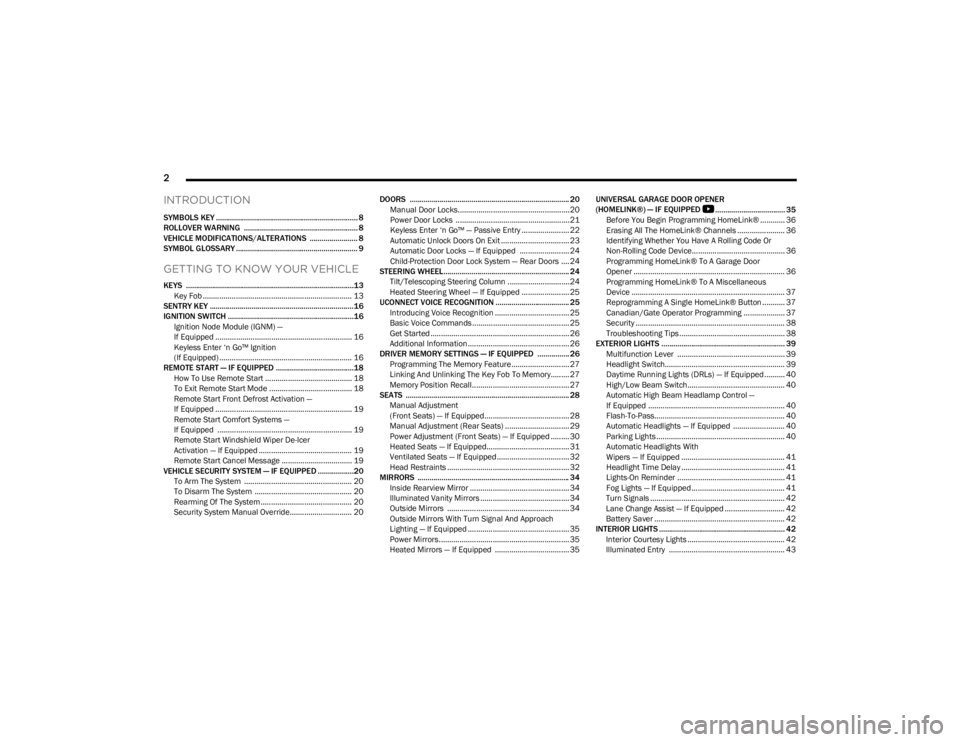
INTRODUCTION
SYMBOLS KEY ....................................................................... 8
ROLLOVER WARNING ......................................................... 8
VEHICLE MODIFICATIONS/ALTERATIONS ........................ 8
SYMBOL GLOSSARY ............................................................. 9
GETTING TO KNOW YOUR VEHICLE
KEYS ....................................................................................13Key Fob ........................................................................ 13
SENTRY KEY ........................................................................16
IGNITION SWITCH ...............................................................16 Ignition Node Module (IGNM) —
If Equipped .................................................................. 16
Keyless Enter ‘n Go™ Ignition
(If Equipped) ................................................................ 16
REMOTE START — IF EQUIPPED .......................................18 How To Use Remote Start .......................................... 18
To Exit Remote Start Mode ........................................ 18
Remote Start Front Defrost Activation —
If Equipped .................................................................. 19
Remote Start Comfort Systems —
If Equipped ................................................................. 19
Remote Start Windshield Wiper De-Icer
Activation — If Equipped ............................................. 19
Remote Start Cancel Message .................................. 19
VEHICLE SECURITY SYSTEM — IF EQUIPPED ..................20 To Arm The System .................................................... 20
To Disarm The System ............................................... 20
Rearming Of The System ............................................ 20
Security System Manual Override.............................. 20 DOORS ................................................................................ 20
Manual Door Locks......................................................20
Power Door Locks .......................................................21
Keyless Enter ‘n Go™ — Passive Entry ....................... 22
Automatic Unlock Doors On Exit ................................. 23
Automatic Door Locks — If Equipped ........................ 24
Child-Protection Door Lock System — Rear Doors .... 24
STEERING WHEEL............................................................... 24 Tilt/Telescoping Steering Column ..............................24
Heated Steering Wheel — If Equipped ....................... 25
UCONNECT VOICE RECOGNITION ..................................... 25 Introducing Voice Recognition .................................... 25
Basic Voice Commands............................................... 25
Get Started ................................................................... 26
Additional Information................................................. 26
DRIVER MEMORY SETTINGS — IF EQUIPPED ................ 26 Programming The Memory Feature............................ 27
Linking And Unlinking The Key Fob To Memory......... 27
Memory Position Recall............................................... 27
SEATS .................................................................................. 28 Manual Adjustment
(Front Seats) — If Equipped......................................... 28
Manual Adjustment (Rear Seats) ............................... 29
Power Adjustment (Front Seats) — If Equipped ......... 30
Heated Seats — If Equipped........................................ 31
Ventilated Seats — If Equipped................................... 32
Head Restraints ........................................................... 32
MIRRORS ............................................................................ 34 Inside Rearview Mirror ................................................ 34
Illuminated Vanity Mirrors ........................................... 34
Outside Mirrors ........................................................... 34
Outside Mirrors With Turn Signal And Approach
Lighting — If Equipped ................................................. 35
Power Mirrors...............................................................35
Heated Mirrors — If Equipped .................................... 35 UNIVERSAL GARAGE DOOR OPENER
(HOMELINK®) — IF EQUIPPED
S
................................... 35
Before You Begin Programming HomeLink® ............ 36
Erasing All The HomeLink® Channels ....................... 36
Identifying Whether You Have A Rolling Code Or
Non-Rolling Code Device............................................. 36
Programming HomeLink® To A Garage Door
Opener ......................................................................... 36
Programming HomeLink® To A Miscellaneous
Device .......................................................................... 37
Reprogramming A Single HomeLink® Button ........... 37
Canadian/Gate Operator Programming .................... 37
Security ........................................................................ 38
Troubleshooting Tips ................................................... 38
EXTERIOR LIGHTS .............................................................. 39 Multifunction Lever .................................................... 39
Headlight Switch.......................................................... 39
Daytime Running Lights (DRLs) — If Equipped .......... 40
High/Low Beam Switch............................................... 40
Automatic High Beam Headlamp Control —
If Equipped .................................................................. 40
Flash-To-Pass............................................................... 40
Automatic Headlights — If Equipped ......................... 40
Parking Lights .............................................................. 40
Automatic Headlights With
Wipers — If Equipped .................................................. 41
Headlight Time Delay .................................................. 41
Lights-On Reminder .................................................... 41
Fog Lights — If Equipped ............................................. 41
Turn Signals ................................................................. 42
Lane Change Assist — If Equipped ............................. 42
Battery Saver ............................................................... 42
INTERIOR LIGHTS ............................................................... 42 Interior Courtesy Lights ............................................... 42
Illuminated Entry ........................................................ 43
23_KL_OM_EN_USC_t.book Page 2
Page 5 of 276
3
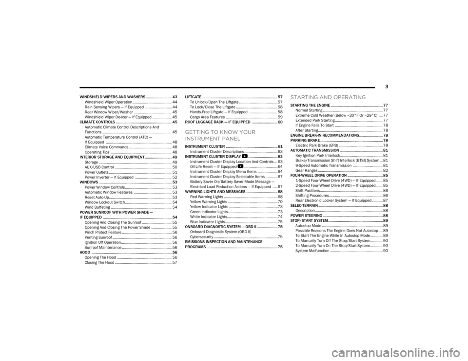
WINDSHIELD WIPERS AND WASHERS ........................... 43Windshield Wiper Operation....................................... 44
Rain Sensing Wipers — If Equipped .......................... 44
Rear Window Wiper/Washer ..................................... 45
Windshield Wiper De-Icer — If Equipped ................... 45
CLIMATE CONTROLS ..........................................................45 Automatic Climate Control Descriptions And
Functions ..................................................................... 45
Automatic Temperature Control (ATC) —
If Equipped ................................................................. 48
Climate Voice Commands .......................................... 48
Operating Tips ............................................................ 48
INTERIOR STORAGE AND EQUIPMENT ............................49 Storage ........................................................................ 49
AUX/USB Control ........................................................ 50
Power Outlets .............................................................. 51
Power Inverter — If Equipped .................................... 52
WINDOWS ...........................................................................53 Power Window Controls .............................................. 53
Automatic Window Features ..................................... 53
Reset Auto-Up.............................................................. 53
Window Lockout Switch.............................................. 54
Wind Buffeting ............................................................ 54
POWER SUNROOF WITH POWER SHADE —
IF EQUIPPED ....................................................................... 54 Opening And Closing The Sunroof ............................. 55
Opening And Closing The Power Shade .................... 55
Pinch Protect Feature ................................................. 56
Venting Sunroof .......................................................... 56
Ignition Off Operation.................................................. 56
Sunroof Maintenance ................................................. 56
HOOD ...................................................................................56 Opening The Hood ...................................................... 56
Closing The Hood ........................................................ 57 LIFTGATE .............................................................................. 57
To Unlock/Open The Liftgate ......................................57
To Lock/Close The Liftgate ......................................... 58
Hands-Free Liftgate — If Equipped ............................ 58
Cargo Area Features ................................................... 59
ROOF LUGGAGE RACK — IF EQUIPPED .......................... 60
GETTING TO KNOW YOUR
INSTRUMENT PANEL
INSTRUMENT CLUSTER ..................................................... 61 Instrument Cluster Descriptions ................................. 63
INSTRUMENT CLUSTER DISPLAY
S
.............................. 63
Instrument Cluster Display Location And Controls.... 63
Oil Life Reset — If Equipped
S
................................. 64
Instrument Cluster Display Menu Items ................... 64
Instrument Cluster Display Selectable Items ............ 67
Battery Saver On/Battery Saver Mode Message —
Electrical Load Reduction Actions — If Equipped .....67
WARNING LIGHTS AND MESSAGES ................................ 68 Red Warning Lights ..................................................... 68
Yellow Warning Lights ................................................. 70
Yellow Indicator Lights ................................................ 73
Green Indicator Lights ................................................. 73
White Indicator Lights.................................................. 74
Blue Indicator Lights.................................................... 75
ONBOARD DIAGNOSTIC SYSTEM — OBD II ..................... 75 Onboard Diagnostic System (OBD II)
Cybersecurity ...............................................................75
EMISSIONS INSPECTION AND MAINTENANCE
PROGRAMS ........................................................................ 75
STARTING AND OPERATING
STARTING THE ENGINE ..................................................... 77 Normal Starting ........................................................... 77
Extreme Cold Weather (Below –20°F Or −29°C) .... 77
Extended Park Starting ............................................... 77
If Engine Fails To Start ............................................... 78
After Starting................................................................ 78
ENGINE BREAK-IN RECOMMENDATIONS........................ 78
PARKING BRAKE ................................................................ 78 Electric Park Brake (EPB) ........................................... 78
AUTOMATIC TRANSMISSION ............................................ 81 Key Ignition Park Interlock.......................................... 81
Brake/Transmission Shift Interlock (BTSI) System ... 81
9-Speed Automatic Transmission ............................. 81
Gear Ranges ................................................................ 82
FOUR-WHEEL DRIVE OPERATION .................................... 85 1-Speed Four-Wheel Drive (4WD) — If Equipped....... 85
2-Speed Four-Wheel Drive (4WD) — If Equipped....... 85
Shift Positions.............................................................. 86
Shifting Procedures ..................................................... 86
Rear Electronic Locker System — If Equipped........... 87
SELEC-TERRAIN .................................................................. 88 Description................................................................... 88
POWER STEERING ............................................................. 88
STOP/START SYSTEM........................................................ 89 Autostop Mode ............................................................ 89
Possible Reasons The Engine Does Not Autostop .... 89
To Start The Engine While In Autostop Mode ............ 89
To Manually Turn Off The Stop/Start System............ 90
To Manually Turn On The Stop/Start System ............ 90
System Malfunction .................................................... 90
23_KL_OM_EN_USC_t.book Page 3
Page 11 of 276
9
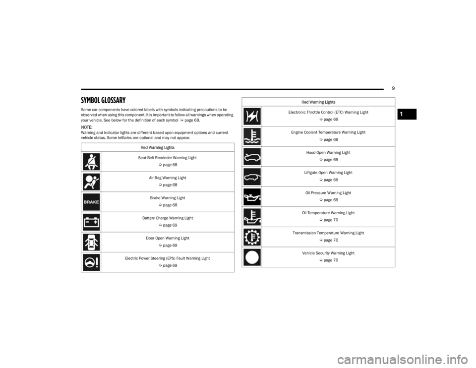
SYMBOL GLOSSARY
Some car components have colored labels with symbols indicating precautions to be
observed when using this component. It is important to follow all warnings when operating
your vehicle. See below for the definition of each symbol
Úpage 68.
NOTE:Warning and Indicator lights are different based upon equipment options and current
vehicle status. Some telltales are optional and may not appear.Red Warning Lights
Seat Belt Reminder Warning Light
Úpage 68
Air Bag Warning Light
Úpage 68
Brake Warning Light
Úpage 68
Battery Charge Warning Light
Úpage 69
Door Open Warning Light
Úpage 69
Electric Power Steering (EPS) Fault Warning Light
Úpage 69
Electronic Throttle Control (ETC) Warning Light
Úpage 69
Engine Coolant Temperature Warning Light
Úpage 69
Hood Open Warning Light
Úpage 69
Liftgate Open Warning Light
Úpage 69
Oil Pressure Warning Light
Úpage 69
Oil Temperature Warning Light
Úpage 70
Transmission Temperature Warning Light
Úpage 70
Vehicle Security Warning Light
Úpage 70
Red Warning Lights
1
23_KL_OM_EN_USC_t.book Page 9
Page 12 of 276
10
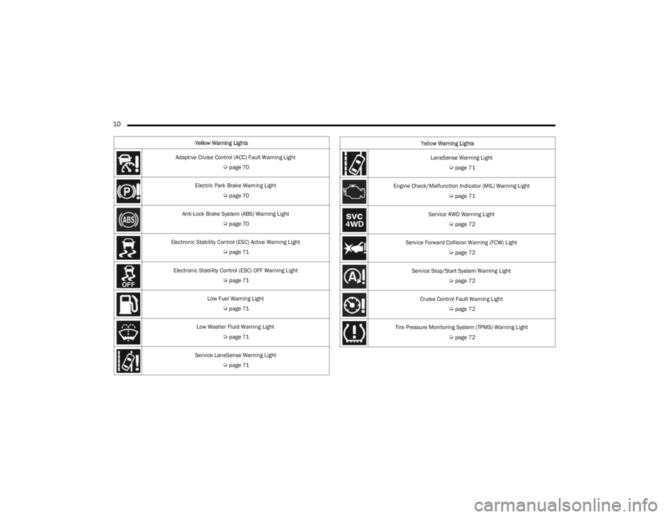
Yellow Warning Lights
Adaptive Cruise Control (ACC) Fault Warning Light
Úpage 70
Electric Park Brake Warning Light
Úpage 70
Anti-Lock Brake System (ABS) Warning Light
Úpage 70
Electronic Stability Control (ESC) Active Warning Light
Úpage 71
Electronic Stability Control (ESC) OFF Warning Light
Úpage 71
Low Fuel Warning Light
Úpage 71
Low Washer Fluid Warning Light
Úpage 71
Service LaneSense Warning Light
Úpage 71
LaneSense Warning Light
Úpage 71
Engine Check/Malfunction Indicator (MIL) Warning Light
Úpage 71
Service 4WD Warning Light
Úpage 72
Service Forward Collision Warning (FCW) Light
Úpage 72
Service Stop/Start System Warning Light
Úpage 72
Cruise Control Fault Warning Light
Úpage 72
Tire Pressure Monitoring System (TPMS) Warning Light
Úpage 72
Yellow Warning Lights
23_KL_OM_EN_USC_t.book Page 10
Page 13 of 276
11
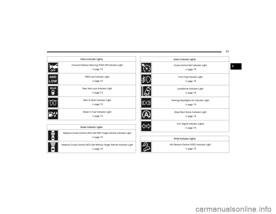
Yellow Indicator Lights
Forward Collision Warning (FCW) Off Indicator Light
Úpage 73
4WD Low Indicator Light
Úpage 73
Rear Axle Lock Indicator Light
Úpage 73
Wait To Start Indicator Light
Úpage 73
Water In Fuel Indicator Light
Úpage 73
Green Indicator Lights
Adaptive Cruise Control (ACC) Set With Target Vehicle Indicator Light
Úpage 73
Adaptive Cruise Control (ACC) Set Without Target Vehicle Indicator Light
Úpage 74
Cruise Control Set Indicator Light
Úpage 74
Front Fog Indicator Light
Úpage 74
LaneSense Indicator Light
Úpage 74
Parking/Headlights On Indicator Light
Úpage 74
Stop/Start Active Indicator Light
Úpage 74
Turn Signal Indicator Lights
Úpage 74
White Indicator Lights
Hill Descent Control (HDC) Indicator Light
Úpage 74
Green Indicator Lights
1
23_KL_OM_EN_USC_t.book Page 11
Page 17 of 276
GETTING TO KNOW YOUR VEHICLE15
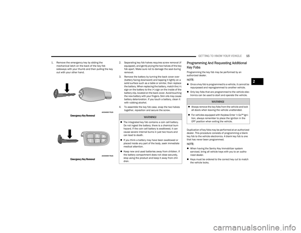
1. Remove the emergency key by sliding the
mechanical latch on the back of the key fob
sideways with your thumb and then pulling the key
out with your other hand.
Emergency Key Removal
Emergency Key Removal
2. Separating key fob halves requires screw removal (if equipped), and gently prying the two halves of the key
fob apart. Make sure not to damage the seal during
removal.
3. Remove the battery by turning the back cover over (battery facing downward) and tapping it lightly on a
solid surface such as a table or similar, then replace
the battery. When replacing the battery, match the (+)
sign on the battery to the (+) sign on the inside of the
battery clip, located on the back cover. Avoid touching
the new battery with your fingers. Skin oils may cause
battery deterioration. If you touch a battery, clean it
with rubbing alcohol.
4. To assemble the key fob case, snap the two halves together, reposition and secure the screw.Programming And Requesting Additional
Key Fobs
Programming the key fob may be performed by an
authorized dealer.
NOTE:
Once a key fob is programmed to a vehicle, it cannot be
repurposed and reprogrammed to another vehicle.
Only key fobs that are programmed to the vehicle elec -
tronics can be used to start and operate the vehicle.
Duplication of key fobs may be performed at an authorized
dealer. This procedure consists of programming a blank
key fob to the vehicle electronics. A blank key fob is one
that has never been programmed.
NOTE:
When having the Sentry Key Immobilizer system
serviced, bring all vehicle keys with you to an autho -
rized dealer.
Keys must be ordered to the correct key cut to match
the vehicle locks.
WARNING!
The integrated key fob contains a coin cell battery.
Do not ingest the battery; there is a chemical burn
hazard. If the coin cell battery is swallowed, it can
cause severe internal burns in just two hours and
can lead to death.
If you think a battery may have been swallowed or
placed inside any part of the body, seek immediate
medical attention.
Keep new and used batteries away from children. If
the battery compartment does not close securely,
stop using the product and keep it away from chil -
dren.
WARNING!
Always remove the key fobs from the vehicle and lock
all doors when leaving the vehicle unattended.
For vehicles equipped with Keyless Enter ‘n Go™ Igni -
tion, always remember to place the ignition in the
OFF position when exiting the vehicle.
2
23_KL_OM_EN_USC_t.book Page 15
Page 20 of 276
18GETTING TO KNOW YOUR VEHICLE
position. In addition to the chime, the message “Igni-
tion or Accessory ON” will display in the cluster.
The power window switches and power sunroof (if
equipped) will remain active for three minutes after the
ignition is placed in the OFF position. Opening either
front door will cancel this feature. The timing for this
feature is programmable.
REMOTE START — IF EQUIPPED
This system uses the key fob to start the engine
conveniently from outside the vehicle while still
maintaining security. The system has a range
of approximately 328 ft (100 m).
Remote Start is used to defrost windows in cold weather,
and to reach a comfortable climate in all ambient
conditions before the driver enters the vehicle.
NOTE:Obstructions between the vehicle and key fob may reduce
this range Úpage 262.
HOW TO USE REMOTE START
Push and release the Remote Start button on the key fob
twice within five seconds. The vehicle doors will lock, the
parking lights will flash, and the horn will chirp (if
programmed within the Uconnect system). Then, the
engine will start, and the vehicle will remain in the Remote
Start mode for a 15 minute cycle. Pushing the Remote
Start button a third time shuts the engine off.
NOTE:
With Remote Start, the engine will only run for
15 minutes.
Remote Start can only be used twice.
The ignition must be placed in the ON/RUN position
before the Remote Start sequence can be repeated for
a third cycle.
If an engine fault is present or fuel level is low, the
vehicle will start and then shut down in 10 seconds.
The parking lights will turn on and remain on during
Remote Start mode.
For security, power window and power sunroof opera -
tion (if equipped) are disabled when the vehicle is in
the Remote Start mode.
The ignition must be placed in the ON/RUN position
before the Remote Start sequence can be repeated for
a third cycle.
All of the following conditions must be met before the
engine will remote start:
Gear selector in PARK
Doors closed
Hood closed
Liftgate closed
Hazard switch off
Brake switch inactive (brake pedal not pressed)
Battery at an acceptable charge level
System not disabled from previous Remote Start event
Vehicle Security system indicator flashing
Ignition in OFF position
Fuel level meets minimum requirement
Vehicle Security system is not signaling an intrusion
Malfunction Indicator Light (MIL) is not illuminated
TO EXIT REMOTE START MODE
To drive the vehicle after starting the Remote Start
system, push and release the START/STOP ignition button
while pressing the brake pedal prior to the end of the
15 minute cycle. If the vehicle is not equipped with a
START/STOP ignition button, insert the key fob into the
ignition switch and place the ignition in the ON/RUN
position.
WARNING!
Do not start or run an engine in a closed garage or
confined area. Exhaust gas contains carbon
monoxide (CO) which is odorless and colorless.
Carbon monoxide is poisonous and can cause
serious injury or death when inhaled.
Keep key fobs away from children. Operation of the
Remote Start system, windows, door locks or other
controls could cause serious injury or death.
23_KL_OM_EN_USC_t.book Page 18
Page 36 of 276
34GETTING TO KNOW YOUR VEHICLE
MIRRORS
INSIDE REARVIEW MIRROR
Auto Dimming Mirror
A single ball joint mirror is provided in the vehicle. It is a
twist on mirror that has a fixed position at the windshield.
The mirror installs on the windshield button with a
counterclockwise rotation and requires no tools for
mounting. The rearview mirror can be adjusted up, down,
left, and right. The mirror should be adjusted to center on
the view through the rear window.
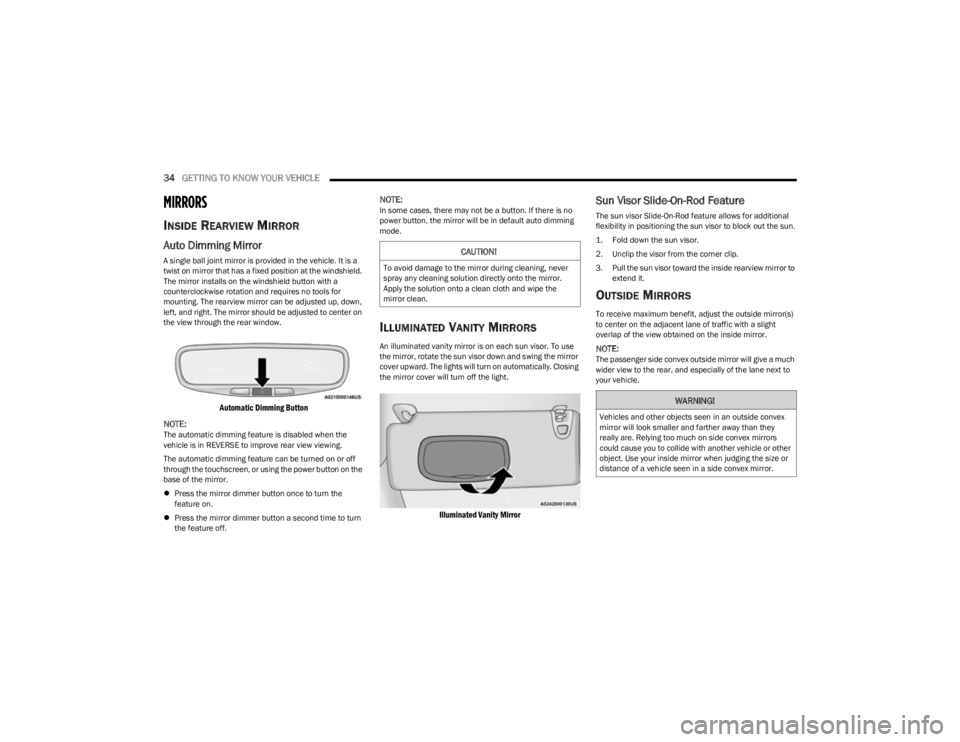
Automatic Dimming Button
NOTE:
The automatic dimming feature is disabled when the
vehicle is in REVERSE to improve rear view viewing.
The automatic dimming feature can be turned on or off
through the touchscreen, or using the power button on the
base of the mirror.
Press the mirror dimmer button once to turn the
feature on.
Press the mirror dimmer button a second time to turn
the feature off.
NOTE:In some cases, there may not be a button. If there is no
power button, the mirror will be in default auto dimming
mode.
ILLUMINATED VANITY MIRRORS
An illuminated vanity mirror is on each sun visor. To use
the mirror, rotate the sun visor down and swing the mirror
cover upward. The lights will turn on automatically. Closing
the mirror cover will turn off the light.
Illuminated Vanity Mirror
Sun Visor Slide-On-Rod Feature
The sun visor Slide-On-Rod feature allows for additional
flexibility in positioning the sun visor to block out the sun.
1. Fold down the sun visor.
2. Unclip the visor from the corner clip.
3. Pull the sun visor toward the inside rearview mirror to
extend it.
OUTSIDE MIRRORS
To receive maximum benefit, adjust the outside mirror(s)
to center on the adjacent lane of traffic with a slight
overlap of the view obtained on the inside mirror.
NOTE:The passenger side convex outside mirror will give a much
wider view to the rear, and especially of the lane next to
your vehicle.
CAUTION!
To avoid damage to the mirror during cleaning, never
spray any cleaning solution directly onto the mirror.
Apply the solution onto a clean cloth and wipe the
mirror clean.
WARNING!
Vehicles and other objects seen in an outside convex
mirror will look smaller and farther away than they
really are. Relying too much on side convex mirrors
could cause you to collide with another vehicle or other
object. Use your inside mirror when judging the size or
distance of a vehicle seen in a side convex mirror.
23_KL_OM_EN_USC_t.book Page 34
Page 37 of 276
GETTING TO KNOW YOUR VEHICLE35
OUTSIDE MIRRORS WITH TURN SIGNAL
A
ND APPROACH LIGHTING —
I
F EQUIPPED
Driver and passenger outside mirrors with turn signal and
approach lighting contain LEDs.
The LEDs are turn signal indicators, which flash with the
corresponding turn signal lights in the front and rear of the
vehicle. Turning on the Hazard Warning flashers will also
activate these LEDs.
The LEDs also supplies illuminated entry lighting, which
turns on in both mirrors when you use the key fob or open
any door. This LED shines downward to illuminate the
ground in front of the doors.
The illuminated entry lighting fades to off after about 30
seconds or it will fade to off immediately once the ignition
is placed into the ON/RUN position.
NOTE:The approach lighting will not function when the gear
selector is moved out of the PARK position.
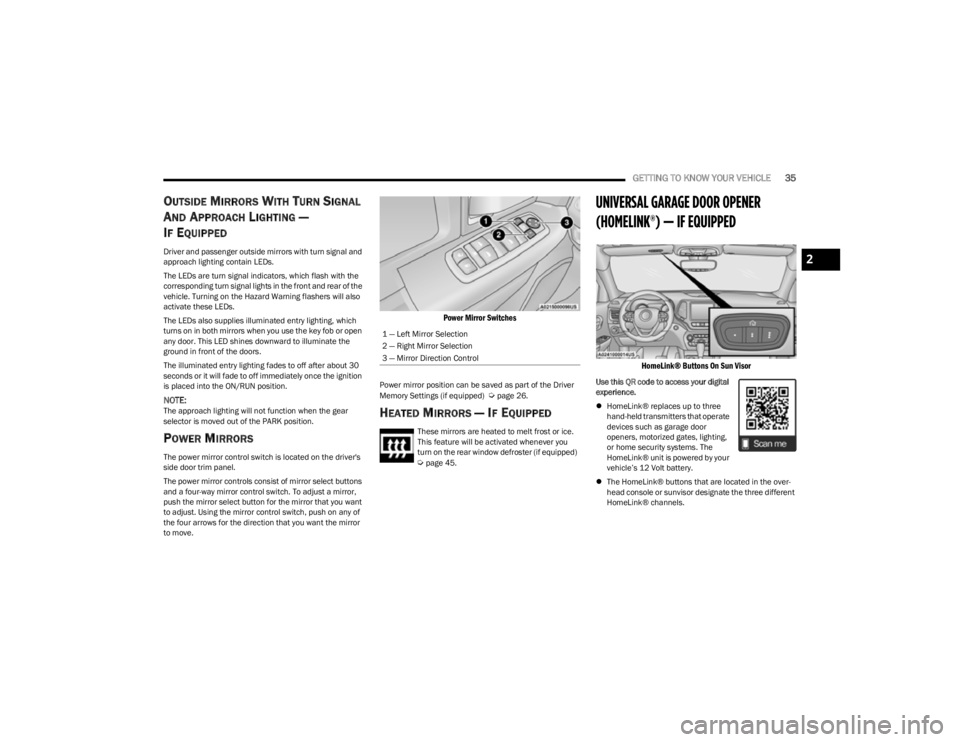
POWER MIRRORS
The power mirror control switch is located on the driver's
side door trim panel.
The power mirror controls consist of mirror select buttons
and a four-way mirror control switch. To adjust a mirror,
push the mirror select button for the mirror that you want
to adjust. Using the mirror control switch, push on any of
the four arrows for the direction that you want the mirror
to move.
Power Mirror Switches
Power mirror position can be saved as part of the Driver
Memory Settings (if equipped) Úpage 26.
HEATED MIRRORS — IF EQUIPPED
These mirrors are heated to melt frost or ice.
This feature will be activated whenever you
turn on the rear window defroster (if equipped)
Úpage 45.
UNIVERSAL GARAGE DOOR OPENER
(HOMELINK®) — IF EQUIPPED
HomeLink® Buttons On Sun Visor
Use this QR code to access your digital
experience.
HomeLink® replaces up to three
hand-held transmitters that operate
devices such as garage door
openers, motorized gates, lighting,
or home security systems. The
HomeLink® unit is powered by your
vehicle’s 12 Volt battery.
The HomeLink® buttons that are located in the over -
head console or sunvisor designate the three different
HomeLink® channels.
1 — Left Mirror Selection
2 — Right Mirror Selection
3 — Mirror Direction Control
2
23_KL_OM_EN_USC_t.book Page 35
Page 39 of 276
GETTING TO KNOW YOUR VEHICLE37
Rolling Code Garage Door Opener Final Steps
NOTE:You have 30 seconds in which to initiate rolling code final
step 2, after completing rolling code final step 1.
1. At the garage door opener motor (in the garage),
locate the “LEARN” or “TRAIN” button. This can
usually be found where the hanging antenna wire is
attached to the garage door opener motor. Firmly
push and release the “LEARN” or “TRAIN” button.
2. Return to the vehicle and push the programmed HomeLink® button three times (holding the button
for two seconds each time). If the garage door opener
motor operates, programming is complete.
3. Push the programmed HomeLink® button to confirm that the garage door opener motor operates. If the
garage door opener motor does not operate, repeat
the final steps for the rolling code procedure.
Non-Rolling Code Garage Door Opener Final Steps
1. Push and hold the programmed HomeLink® button and observe the HomeLink® indicator light. If the
HomeLink® indicator light stays on constantly,
programming is complete.
2. Push the programmed HomeLink® button to confirm that the garage door opener motor operates. If the
garage door opener motor does not operate, repeat
the steps from the beginning.
PROGRAMMING HOMELINK® TO A
M
ISCELLANEOUS DEVICE
The procedure on how to program HomeLink® to a
miscellaneous device follows the same procedure as
programming to a garage door opener
Úpage 36. Be sure
to determine if the device has a rolling code, or non-rolling
code before beginning the programming process.
NOTE:Canadian Radio Frequency (RF) laws require transmitter
signals to time-out (or quit) after several seconds of trans -
mission, which may not be long enough for HomeLink® to
pick up the signal during programming. Similar to this
Canadian law, some U.S. gate operators are designed to
time-out in the same manner. The procedure may need to
be performed multiple times to successfully pair the
device to your HomeLink® buttons.
REPROGRAMMING A SINGLE
H
OMELINK® BUTTON
To reprogram a single HomeLink® button that has been
previously trained, without erasing all the channels,
proceed as follows. Be sure to determine whether the new
device you want to program the HomeLink® button to has
a rolling code, or non-rolling code.
1. Place the ignition in the ON/RUN position, without
starting the engine.
2. Push and hold the desired HomeLink® button until the HomeLink® indicator light begins to flash after
20 seconds. Do not release the button.
3. Without releasing the button , proceed with Step 2 in
“Programming HomeLink® To A Garage Door
Opener” and follow all remaining steps.
CANADIAN/GATE OPERATOR
P
ROGRAMMING
For programming transmitters in Canada/United States
that require the transmitter signals to “time-out” after
several seconds of transmission:
Canadian Radio Frequency (RF) laws require transmitter
signals to time-out (or quit) after several seconds of
transmission, which may not be long enough for
HomeLink® to pick up the signal during programming.
Similar to this Canadian law, some U.S. gate operators are
designed to time-out in the same manner.
WARNING!
Your motorized door or gate will open and close while
you are programming the universal transmitter. Do
not program the transmitter if people or pets are in
the path of the door or gate.
Do not run your vehicle in a closed garage or
confined area while programming the transmitter.
Exhaust gas from your vehicle contains carbon
monoxide (CO) which is odorless and colorless.
Carbon monoxide is poisonous when inhaled and
can cause you and others to be severely injured or
killed.
2
23_KL_OM_EN_USC_t.book Page 37