lug JEEP CHEROKEE LATITUDE 2015 Owners Manual
[x] Cancel search | Manufacturer: JEEP, Model Year: 2015, Model line: CHEROKEE LATITUDE, Model: JEEP CHEROKEE LATITUDE 2015Pages: 764, PDF Size: 5 MB
Page 83 of 764
WARNING!
•Your vehicle is equipped with left and right
Supplemental Side Air Bag Inflatable Curtains
(SABICs). Do not stack luggage or other cargo up
high enough to block the deployment of the
SABICs. The trim covering above the side win-
dows where the SABIC and its deployment path
are located should remain free from any obstruc-
tions.
• Your vehicle is equipped with SABICs. In order for
the SABICs to work as intended, do not install any
accessory items in your vehicle which could alter
the roof. Do not add an aftermarket sunroof to your
vehicle. Do not add roof racks that require perma-
nent attachments (bolts or screws) for installation
on the vehicle roof. Do not drill into the roof of the
vehicle for any reason. The SABICs and SABs (“Side Air Bags”) are designed to
activate in certain side impacts and certain rollover
events. The Occupant Restraint Controller (“ORC”) de-
termines whether the deployment of the Side Air Bags in
a particular side impact or rollover event is appropriate,
based on the severity and type of collision. Vehicle
damage by itself is not a good indicator of whether or not
Side Air Bags should have deployed.
Side Air Bags are a supplement to the seat belt restraint
system. Side Air Bags deploy in less time than it takes to
blink your eyes. Occupants, including children, who are
up against or very close to Side Air Bags can be seriously
injured or killed. Occupants, including children, should
never lean on or sleep against the door, side windows, or
area where the Side Air Bags inflate, even if they are in an
infant or child restraint.
Seat belts (and child restraints where appropriate) are
necessary for your protection in all collisions. They also2
THINGS TO KNOW BEFORE STARTING YOUR VEHICLE 81
Page 312 of 764
WARNING!(Continued)
•Do not pile luggage or cargo higher than the top of
the seatback. This could impair visibility or be-
come a dangerous projectile in a sudden stop or
accident.
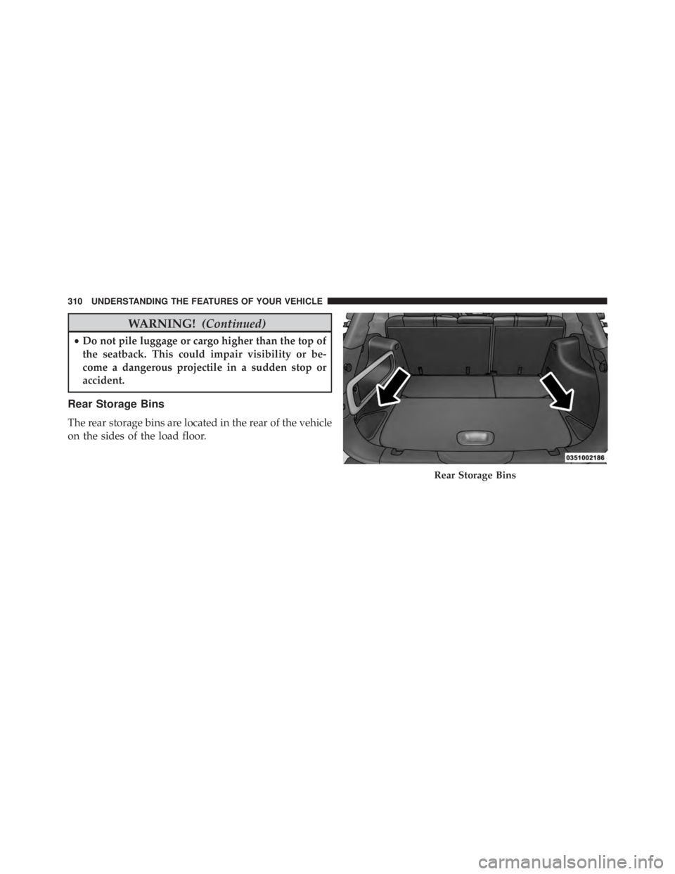
Rear Storage Bins
The rear storage bins are located in the rear of the vehicle
on the sides of the load floor.
Page 465 of 764
NOTE:
•The engine block heater cord is a factory installed
option. If your vehicle is not equipped, heater cords
are available from your authorized MOPAR® dealer.
• The engine block heater will require 110 Volts AC and
6.5 Amps to activate the heater element.
• The engine block heater must be plugged in at least
one hour to have an adequate warming effect on the
engine.
Page 538 of 764
WARNING!(Continued)
•Unequal tire pressures from one side of the vehicle
to the other can cause the vehicle to drift to the
right or left.
• Always drive with each tire inflated to the recom-
mended cold tire inflation pressure.
Both under-inflation and over-inflation affect the stability
of the vehicle and can produce a feeling of sluggish
response or over responsiveness in the steering.
NOTE:
• Unequal tire pressures from side to side may cause
erratic and unpredictable steering response.
• Unequal tire pressure from side to side may cause the
vehicle to drift left or right.
Fuel Economy
Underinflated tires will increase tire rolling resistance
resulting in higher fuel consumption.
Tread Wear
Improper cold tire inflation pressures can cause abnor-
mal wear patterns and reduced tread life, resulting in the
need for earlier tire replacement.
Ride Comfort And Vehicle Stability
Proper tire inflation contributes to a comfortable ride.
Over-inflation produces a jarring and uncomfortable
ride.
536 STARTING AND OPERATING
Page 583 of 764
WARNING!
It is important that you do not exceed the maximum
front or rear GAWR. A dangerous driving condition
can result if either rating is exceeded. You could lose
control of the vehicle and have a collision.
Tongue Weight (TW)
The tongue weight is the downward force exerted on the
hitch ball by the trailer. The recommended tongue weight
is 10% to 15% of the vehicle’s GTW for a conventional
hitch. You must consider this as part of the load on your
vehicle.
Frontal Area
The frontal area is the maximum height multiplied by the
maximum width of the front of a trailer.
Trailer Sway Control — Mechanical
The trailer sway control is a telescoping link that can be
installed between the hitch receiver and the trailer tongue
that typically provides adjustable friction associated with
the telescoping motion to dampen any unwanted trailer
swaying motions while traveling.
Weight-Carrying Hitch
A weight-carrying hitch supports the trailer tongue
weight, just as if it were luggage located at a hitch ball or
some other connecting point of the vehicle. These kinds
of hitches are the most popular on the market today and
they are commonly used to tow small and medium sized
trailers.
5
STARTING AND OPERATING 581
Page 610 of 764
WARNING!
To avoid the risk of forcing the vehicle off the jack,
do not tighten the lug nuts fully until the vehicle has
been lowered. Failure to follow this warning may
result in personal injury.
TIRE SERVICE KIT — IF EQUIPPED
Small punctures up to ¼” (6 mm) in the tire tread can be
sealed with Tire Service Kit. Foreign objects (e.g., screws
or nails) should not be removed from the tire. Tire Service
Kit can be used in outside temperatures down to approxi-
mately -4°F (-20°C).
This kit will provide a temporary tire seal, allowing you
to drive your vehicle up to 100 miles (160 km) with a
maximum speed of 55 mph (90 km/h).
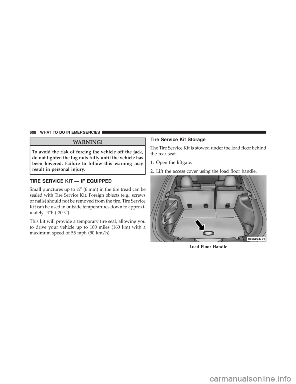
Tire Service Kit Storage
The Tire Service Kit is stowed under the load floor behind
the rear seat.
1. Open the liftgate.
2. Lift the access cover using the load floor handle.
Page 632 of 764
WARNING!
To avoid the risk of forcing the vehicle off the jack,
do not tighten the lug nuts fully until the vehicle has
been lowered. Failure to follow this warning may
result in serious injury.
3. Lower the vehicle to the ground by turning the jack handle counterclockwise.
4. Finish tightening the wheel bolts. Push down on the wrench while at the end of the handle for increased
leverage. Tighten the wheel bolts in a star pattern until
each wheel bolt has been tightened twice. Refer to
“Torque Specifications” in this section for the proper
lug bolt torque. If in doubt about the correct tightness,
have them checked with a torque wrench by your
authorized dealer or service station. 5. Lower the jack until it is free. Remove the wheel
chocks. Reassemble the lug wrench to the jack assem-
bly and stow it in the spare tire area. Secure the
assembly using the means provided. Release the park-
ing brake before driving the vehicle.
6. After 25 miles (40 km) check the wheel bolt torque with a torque wrench to ensure that all wheel bolts are
properly seated against the wheel.
JUMP-STARTING PROCEDURES
If your vehicle has a discharged battery it can be jump-
started using a set of jumper cables and a battery in
another vehicle or by using a portable battery booster
pack. Jump-starting can be dangerous if done improperly
so please follow the procedures in this section carefully.
NOTE:
When using a portable battery booster pack follow
the manufacturer ’s operating instructions and precautions.
630 WHAT TO DO IN EMERGENCIES
Page 679 of 764
Under normal operating conditions, the catalytic con-
verter will not require maintenance. However, it is im-
portant to keep the engine properly tuned to assure
proper catalyst operation and prevent possible catalyst
damage.
NOTE:Intentional tampering with emissions control
systems can result in civil penalties being assessed
against you.
In unusual situations involving grossly malfunctioning
engine operation, a scorching odor may suggest severe
and abnormal catalyst overheating. If this occurs, stop
the vehicle, turn off the engine and allow it to cool.
Service, including a tune-up to manufacturer’s specifica-
tions, should be obtained immediately.
To minimize the possibility of catalytic converter damage:
• Do not shut off the engine or interrupt the ignition,
when the transmission is in gear and the vehicle is in
motion. •
Do not try to start the engine by pushing or towing the
vehicle.
• Do not idle the engine with any spark plug wires
disconnected or removed, such as when diagnostic
testing, or for prolonged periods during very rough
idle or malfunctioning operating conditions.
Cooling System
Page 729 of 764
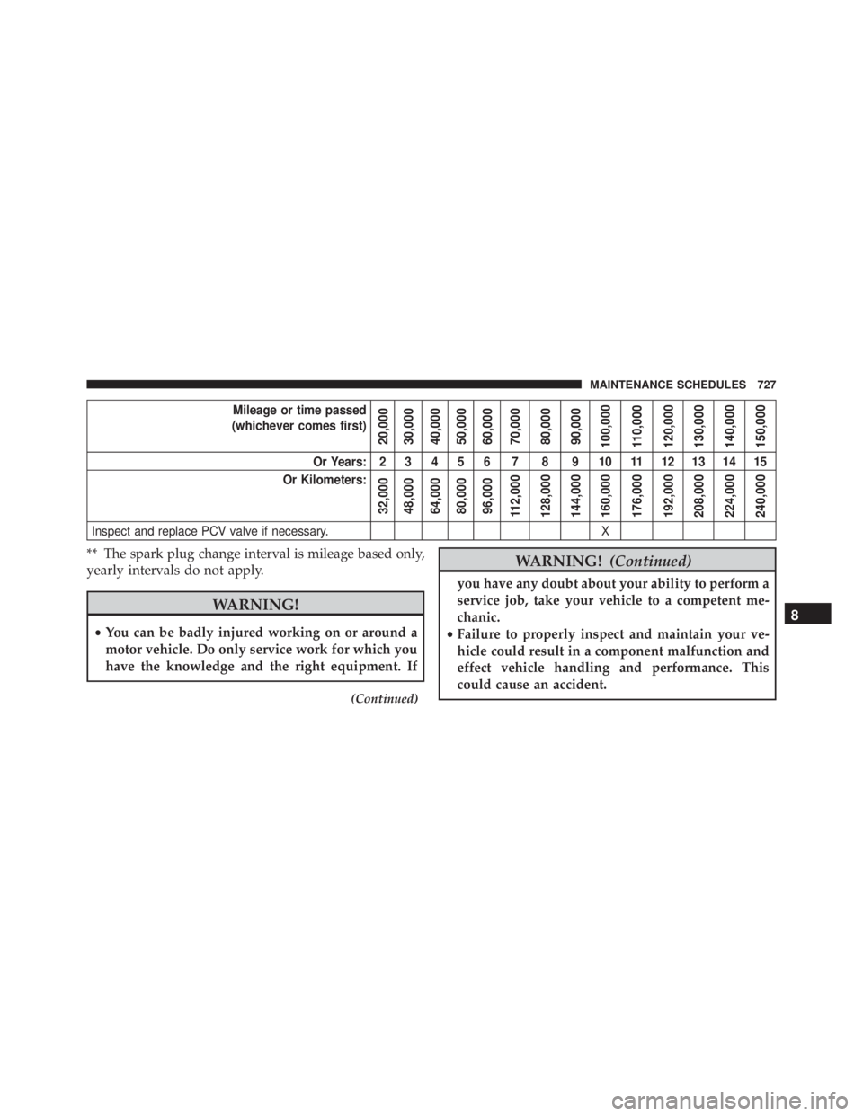
Mileage or time passed
(whichever comes first)
20,000
30,000
40,000
50,000
60,000
70,000
80,000
90,000
100,000
110,000
120,000
130,000
140,000
150,000
Or Years: 2 3 4 5 6 7 8 9 10 11 12 13 14 15
Or Kilometers:
32,000
48,000
64,000
80,000
96,000
112,000
128,000
144,000
160,000
176,000
192,000
208,000
224,000
240,000
Inspect and replace PCV valve if necessary. X
** The spark plug change interval is mileage based only,
yearly intervals do not apply.