warning JEEP CHEROKEE LATITUDE 2016 Owner's Guide
[x] Cancel search | Manufacturer: JEEP, Model Year: 2016, Model line: CHEROKEE LATITUDE, Model: JEEP CHEROKEE LATITUDE 2016Pages: 788, PDF Size: 5.13 MB
Page 218 of 788
WARNING!
In the normal Cruise Control mode, the system will
not react to vehicles ahead. In addition, the proximity
warning does not activate and no alarm will sound
even if you are too close to the vehicle ahead since
neither the presence of the vehicle ahead nor the
vehicle-to vehicle distance is detected. Be sure to
maintain a safe distance between your vehicle and
the vehicle ahead. Always be aware which mode is
selected.
To Set A Desired Speed
Turn the Normal (Fixed Speed) Electronic
Speed Control ON. When the vehicle has
reached the desired speed, push the SET (+) or
SET (-) button and release. Release the accel-
erator and the vehicle will operate at the selected speed. Once a speed has been set a message (CRUISE CON-
TROL SET TO MPH/KM) will appear indicating what
speed was set. This light will turn on when the electronic
speed control is SET.
To Vary The Speed Setting
To Increase Speed
When the Normal (Fixed Speed) Electronic Speed Control
is set, you can increase speed by pushing the SET
+button.
The drivers preferred units can be selected through the
instrument panel settings if equipped. Refer to “Under-
standing Your Instrument Panel” for more information.
The speed increment shown is dependant on the speed of
U.S. (mph) or Metric (km/h) units:
U.S. Speed (mph)
• Pushing the SET +button once will result ina1mph
increase in set speed. Each subsequent tap of the
button results in an increase of 1 mph.
Page 222 of 788
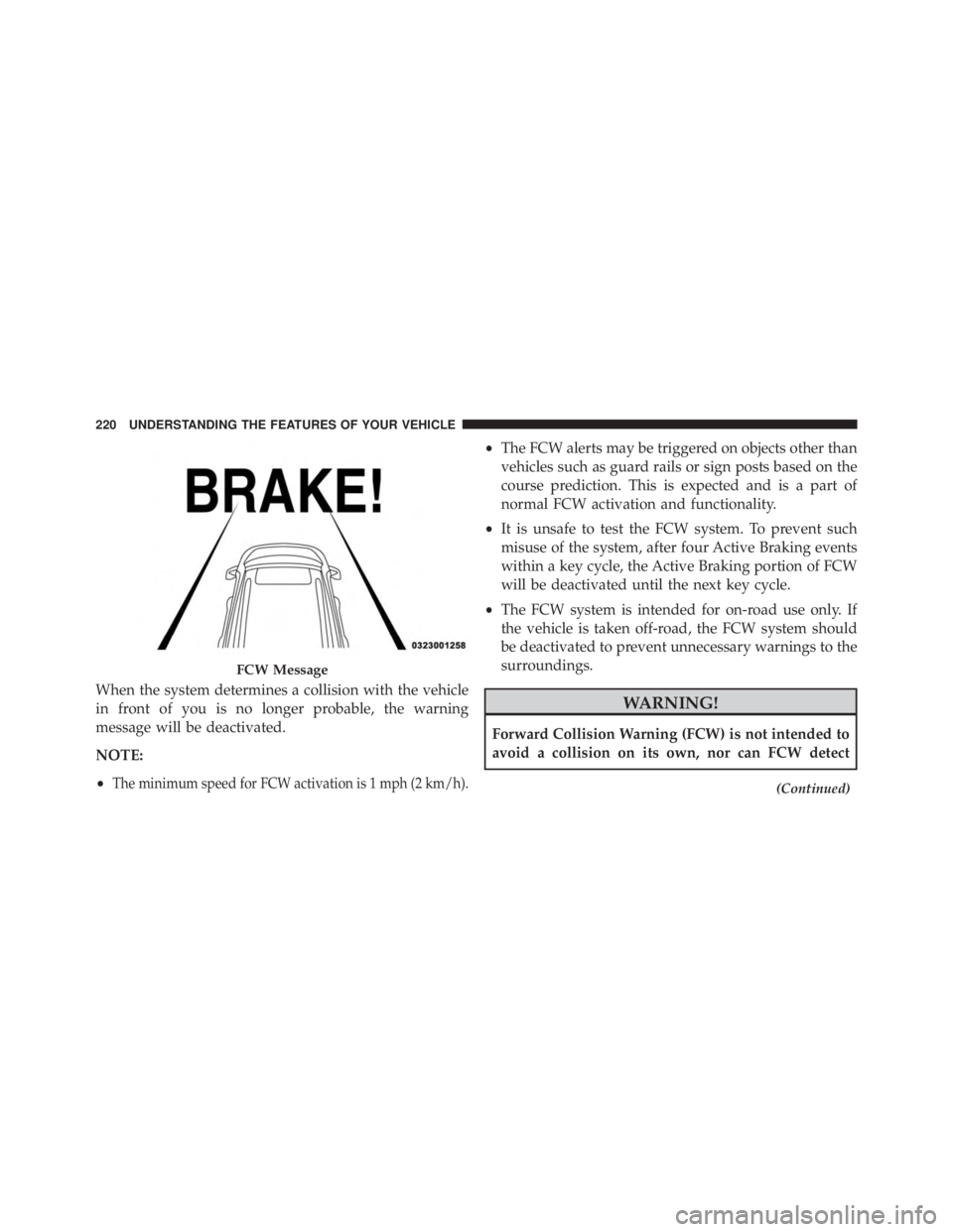
When the system determines a collision with the vehicle
in front of you is no longer probable, the warning
message will be deactivated.
NOTE:
•
The minimum speed for FCW activation is 1 mph (2 km/h).
•The FCW alerts may be triggered on objects other than
vehicles such as guard rails or sign posts based on the
course prediction. This is expected and is a part of
normal FCW activation and functionality.
• It is unsafe to test the FCW system. To prevent such
misuse of the system, after four Active Braking events
within a key cycle, the Active Braking portion of FCW
will be deactivated until the next key cycle.
• The FCW system is intended for on-road use only. If
the vehicle is taken off-road, the FCW system should
be deactivated to prevent unnecessary warnings to the
surroundings.
Page 223 of 788
WARNING!(Continued)
every type of potential collision. The driver has the
responsibility to avoid a collision by controlling the
vehicle via braking and steering. Failure to follow
this warning could lead to serious injury or death.
Turning FCW ON Or OFF
NOTE:The default status of FCW is “On”, this allows
the system to warn you of a possible collision with the
vehicle in front of you.
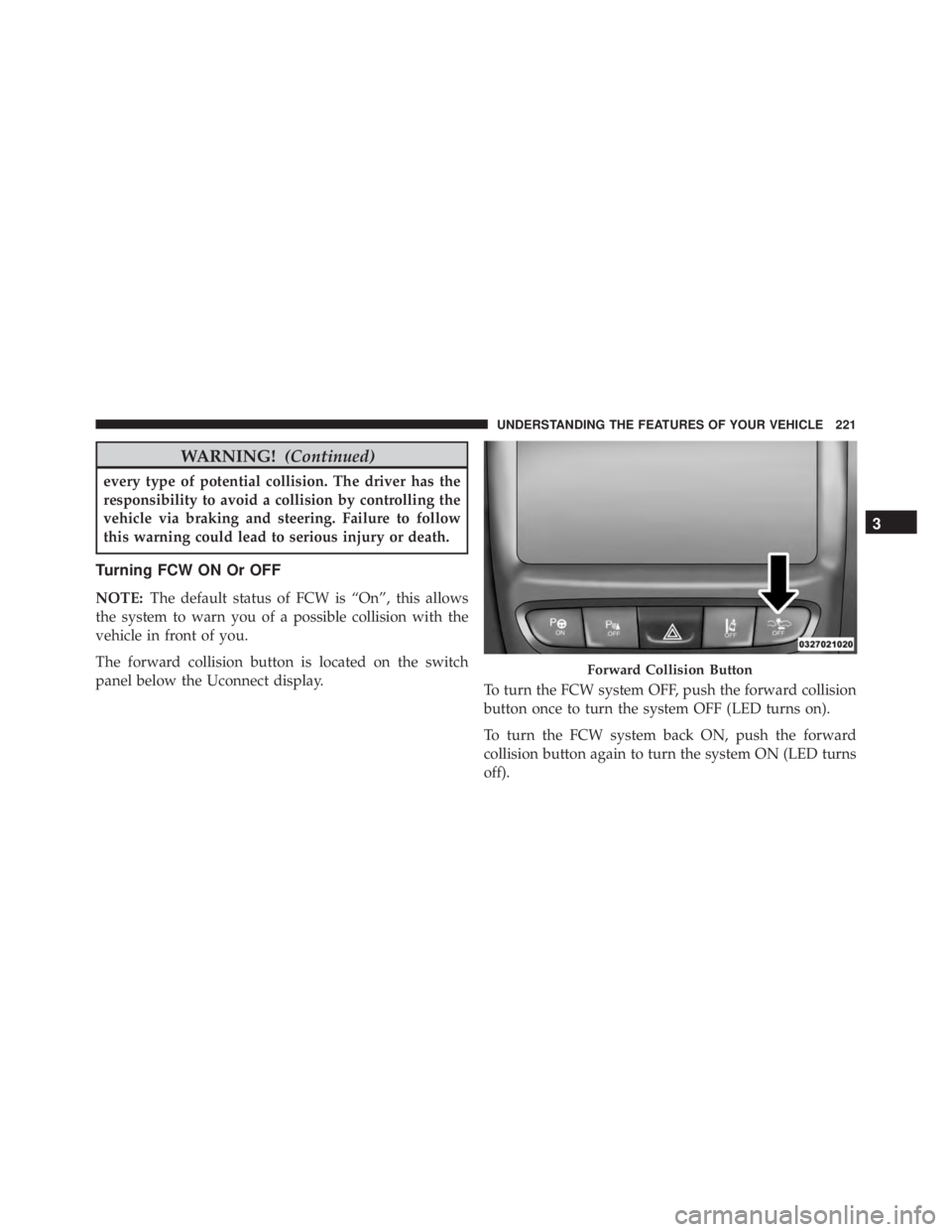
The forward collision button is located on the switch
panel below the Uconnect display. To turn the FCW system OFF, push the forward collision
button once to turn the system OFF (LED turns on).
To turn the FCW system back ON, push the forward
collision button again to turn the system ON (LED turns
off).
Page 262 of 788
WARNING!(Continued)
obstructions, and blind spots before backing up.
You are responsible for safety and must continue to
pay attention to your surroundings. Failure to do so
can result in serious injury or death.
• Before using ParkSense, it is strongly recom-
mended that the ball mount and hitch ball assem-
bly is disconnected from the vehicle when the
vehicle is not used for towing. Failure to do so can
result in injury or damage to vehicles or obstacles
because the hitch ball will be much closer to the
obstacle than the rear fascia when the loudspeaker
sounds the continuous tone. Also, the sensors
could detect the ball mount and hitch ball assem-
bly, depending on its size and shape, giving a false
indication that an obstacle is behind the vehicle.
Page 286 of 788
WARNING!(Continued)
damage to vehicles or obstacles because the hitch
ball will be much closer to the obstacle than the
rear fascia when the loudspeaker sounds the con-
tinuous tone. Also, the sensors could detect the ball
mount and hitch ball assembly, depending on its
size and shape, giving a false indication that an
obstacle is behind the vehicle.
Page 297 of 788
WARNING!(Continued)
after 1982. Do not use a garage door opener without
these safety features. Call toll-free 1-800-355-3515
or, on the Internet at HomeLink.com for safety
information or assistance.
General Information
This device complies with Part 15 of the FCC Rules and
with Industry Canada licence-exempt RSS standard(s).
Operation is subject to the following two conditions:
1. This device may not cause harmful interference, and
2. This device must accept any interference received,
including interference that may cause undesired op-
eration.
NOTE: Changes or modifications not expressly approved
by the party responsible for compliance could void the
user ’s authority to operate the equipment.
POWER SUNROOF WITH POWER SHADE — IF
EQUIPPED
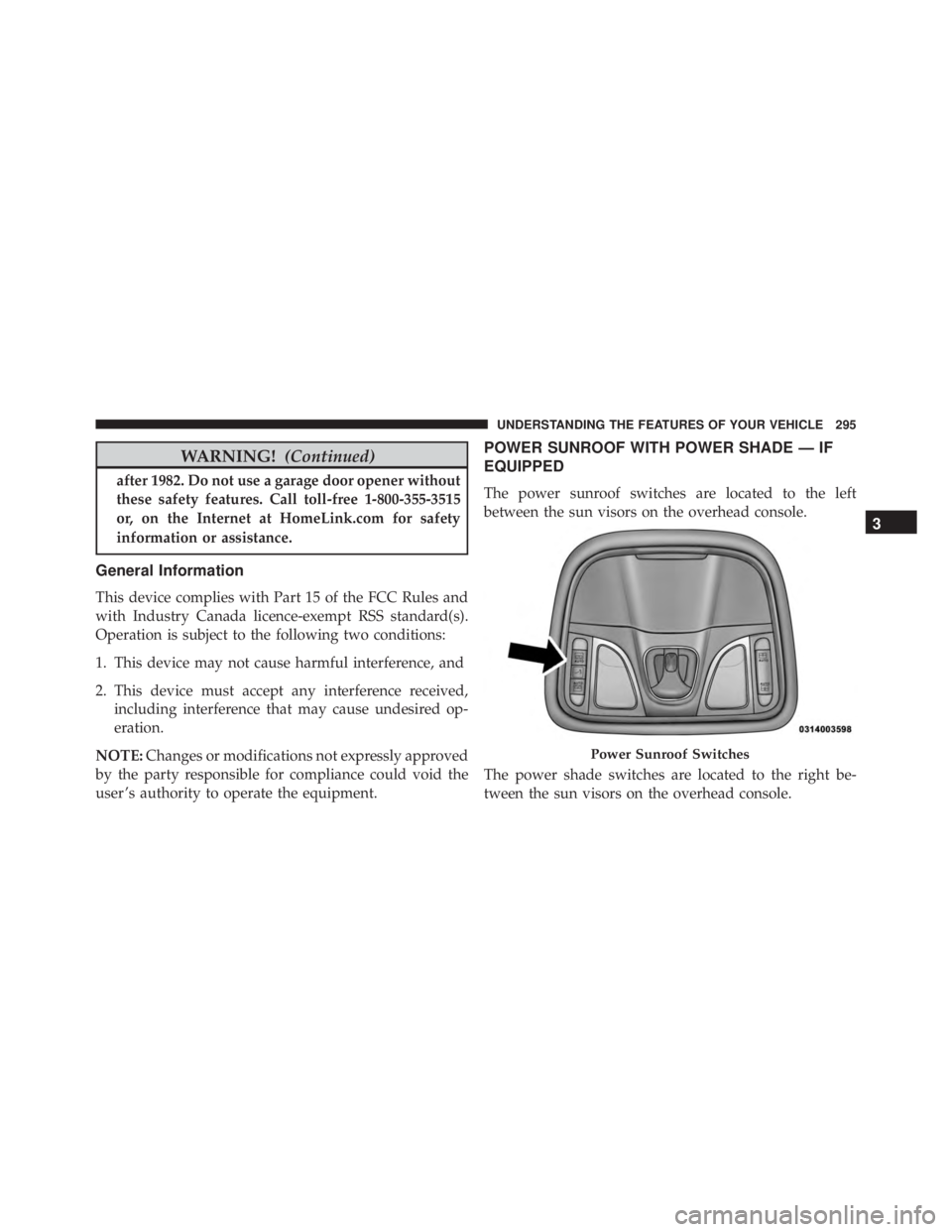
The power sunroof switches are located to the left
between the sun visors on the overhead console.
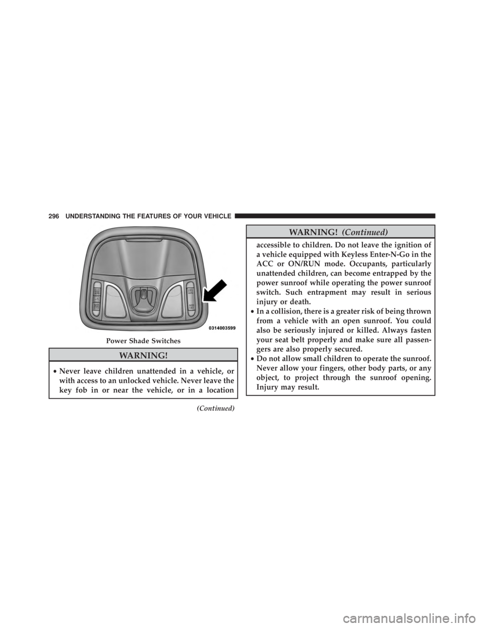
The power shade switches are located to the right be-
tween the sun visors on the overhead console.
Page 298 of 788
WARNING!
•Never leave children unattended in a vehicle, or
with access to an unlocked vehicle. Never leave the
key fob in or near the vehicle, or in a location
(Continued)
Page 305 of 788
WARNING!
To avoid serious injury or death:
•Only devices designed for use in this type of outlet
should be inserted into any 12 Volt outlet.
• Do not touch with wet hands.
• Close the lid when not in use and while driving the
vehicle.
• If this outlet is mishandled, it may cause an electric
shock and failure.
Page 316 of 788
WARNING!
Be certain that the seat cushion is locked securely
into position before using the seat. Otherwise, the
seat will not provide the proper stability for passen-
gers. An improperly latched seat cushion could cause
serious injury.
CARGO AREA FEATURES
Cargo Load Floor
The cargo load floor system has a load capacity of 400 lbs
(181 kg).
To provide additional storage area, each rear seat can be
folded flat. This allows for extended cargo space and still
maintains some rear seating room. Refer to “Seats” in this
section for further information.
Cargo Extension Panels
Cargo extension panels can be folded and unfolded.
When the rear seats are moved to the more forward
positions and the rear seat backs are folded down, the
extension panels can be unfolded manually by hand (2 of
them). The extension panels can be used to extend the
load floor to the rear seats and/or hide the gap between
the load floor and rear seats, or to assist in loading large
items into the cargo area.
Cargo Tie-Down Hooks And Loops
The tie-downs located on the cargo area floor should be
used to secure loads safely when the vehicle is moving.
Cargo tie-down loops are located on the trim panels.
314 UNDERSTANDING THE FEATURES OF YOUR VEHICLE
Page 317 of 788
WARNING!
•Cargo tie-downs are not safe anchors for a child
seat tether strap. In a sudden stop or accident, a
tie-down could pull loose and allow the child seat
to come loose. A child could be badly injured. Use
only the anchors provided for child seat tethers.
• To help protect against personal injury, passengers
should not be seated in the rear cargo area. The rear
cargo space is intended for load carrying purposes
only, not for passengers, who should sit in seats
and use seat belts.