warning JEEP CHEROKEE LIMITED 2017 Owners Manual
[x] Cancel search | Manufacturer: JEEP, Model Year: 2017, Model line: CHEROKEE LIMITED, Model: JEEP CHEROKEE LIMITED 2017Pages: 580, PDF Size: 5.68 MB
Page 2 of 580

VEHICLES SOLD IN CANADA
With respect to any Vehicles Sold in Canada, the name
FCA US LLC shall be deemed to be deleted and the name
FCA Canada Inc. used in substitution therefore.
DRIVING AND ALCOHOL
Drunken driving is one of the most frequent causes of
accidents.
Your driving ability can be seriously impaired with blood
alcohol levels far below the legal minimum. If you are
drinking, don’t drive. Ride with a designated non-
drinking driver, call a cab, a friend, or use public trans-
portation.
WARNING!
Driving after drinking can lead to an accident.
Your perceptions are less sharp, your reflexes are
slower, and your judgment is impaired when you
have been drinking. Never drink and then drive.
This manual illustrates and describes the operation of
features and equipment that are either standard or op-
tional on this vehicle. This manual may also include a
description of features and equipment that are no longer
available or were not ordered on this vehicle. Please
disregard any features and equipment described in this
manual that are not on this vehicle.
FCA US LLC reserves the right to make changes in design
and specifications, and/or make additions to or improve-
ments to its products without imposing any obligation
upon itself to install them on products previously manu-
factured.
Copyright © 2018 FCA US LLC
INSTALLATION OF RADIO TRANSMITTING
EQUIPMENT
Special design considerations are incorporated into this
vehicle’s electronic system to provide immunity to radio
frequency signals. Mobile two-way radios and telephone
equipment must be installed properly by trained person-
nel. The following must be observed during installation.
The positive power connection should be made directly
to the battery and fused as close to the battery as possible.
The negative power connection should be made to body
sheet metal adjacent to the negative battery connection.
This connection should not be fused.
Antennas for two-way radios should be mounted on the
roof or the rear area of the vehicle. Care should be used
in mounting antennas with magnet bases. Magnets may
affect the accuracy or operation of the compass on
vehicles so equipped.
The antenna cable should be as short as practical and
routed away from the vehicle wiring when possible. Use
only fully shielded coaxial cable.
Carefully match the antenna and cable to the radio to
ensure a low Standing Wave Ratio (SWR).Mobile radio equipment with output power greater than
normal may require special precautions.
All installations should be checked for possible interfer-
ence between the communications equipment and the
vehicle’s electronic systems.
WARNING:
Operating, servicing and maintaining a
passenger vehicle or off-road highway
motor vehicle can expose you to chemicals
including engine exhaust, carbon monoxide,
phthalates, and lead, which are known to
the State of California to cause cancer and
birth defects or other reproductive harm.
To minimize exposure, avoid breathing
exhaust, do not idle the engine except as
necessary, service your vehicle in a
well-ventilated area and wear gloves or
wash your hands frequently when servicing
your vehicle. For more information go to
www.P65Warnings.ca.gov/passenger-vehicle.
DID_3635900_18d_Cherokee_OM_EN_060318.indd 27/3/18 7:26 AM
Page 9 of 580
WARNINGS AND CAUTIONS
This Owner ’s Manual containsWARNINGSagainst oper-
ating procedures that could result in a collision, bodily
injury and/or death. It also contains CAUTIONSagainst
procedures that could result in damage to your vehicle.
If you do not read this entire Owner ’s Manual, you may
miss important information. Observe all Warnings and
Cautions.
VEHICLE MODIFICATIONS/ALTERATIONS
Page 32 of 580
WARNING!
•Do not start or run an engine in a closed garage or
confined area. Exhaust gas contains Carbon Monox-
ide (CO) which is odorless and colorless. Carbon
Monoxide is poisonous and can cause serious injury
or death when inhaled.
• Keep key fobs away from children. Operation of the
Remote Start System, windows, door locks or other
controls could cause serious injury or death.
Remote Start Abort Message On The Instrument
Cluster Display
The following messages will display in the instrument
cluster display if the vehicle fails to remote start or exits
remote start prematurely:
• Remote Start Aborted — Door Open
• Remote Start Aborted — Hood Open
• Remote Start Aborted — Fuel Low
• Remote Start Aborted — Liftgate Open
• Remote Start Disabled — Start Vehicle To Reset
• Remote Start Aborted — Too Cold
• Remote Start Aborted — Time Expired The message will stay active until the ignition is turned to
the ON/RUN position.
To Enter Remote Start Mode
Push and release the remote start button on the key fob
twice within five seconds. The vehicle doors will lock, the
parking lights will flash, and the horn will chirp twice (if
programmed). Then, the engine will start, and the vehicle
will remain in the Remote Start mode for a 15-minute cycle.
NOTE:
•
If an engine fault is present or fuel level is low, the
vehicle will start and then shut down in 10 seconds.
• The park lamps will turn on and remain on during
Remote Start mode.
• For security, power window and power sunroof opera-
tion (if equipped) are disabled when the vehicle is in the
Remote Start mode.
• The engine can be started two consecutive times with
the key fob. However, the ignition must be cycled by
pushing the START/STOP button twice (or the ignition
switch must be cycled to the ON/RUN position) before
you can repeat the start sequence for a third cycle.
30 GETTING TO KNOW YOUR VEHICLE
Page 38 of 580
WARNING!
•For personal security and safety in the event of a
collision, lock the vehicle doors before you drive as
well as when you park and exit the vehicle.
• When exiting the vehicle, always remove the key fob
from the vehicle and lock your vehicle. If equipped
with Keyless Enter-N-Go — Ignition, always make
sure the keyless ignition node is in “OFF” mode,
remove the key fob from the vehicle and lock the
vehicle. Unsupervised use of vehicle equipment may
cause severe personal injuries or death.
•
Never leave children alone in a vehicle, or with access
to an unlocked vehicle. Allowing children to be in a
vehicle unattended is dangerous for a number of
reasons. A child or others could be seriously or fatally
injured. Children should be warned not to touch the
parking brake, brake pedal or the gear selector.
• Do not leave the key fob in or near the vehicle, or in
a location accessible to children, and do not leave the
ignition of a vehicle equipped with Keyless Enter-
N-Go — Ignition the ACC or ON/RUN mode. A child
could operate power windows, other controls, or
move the vehicle.
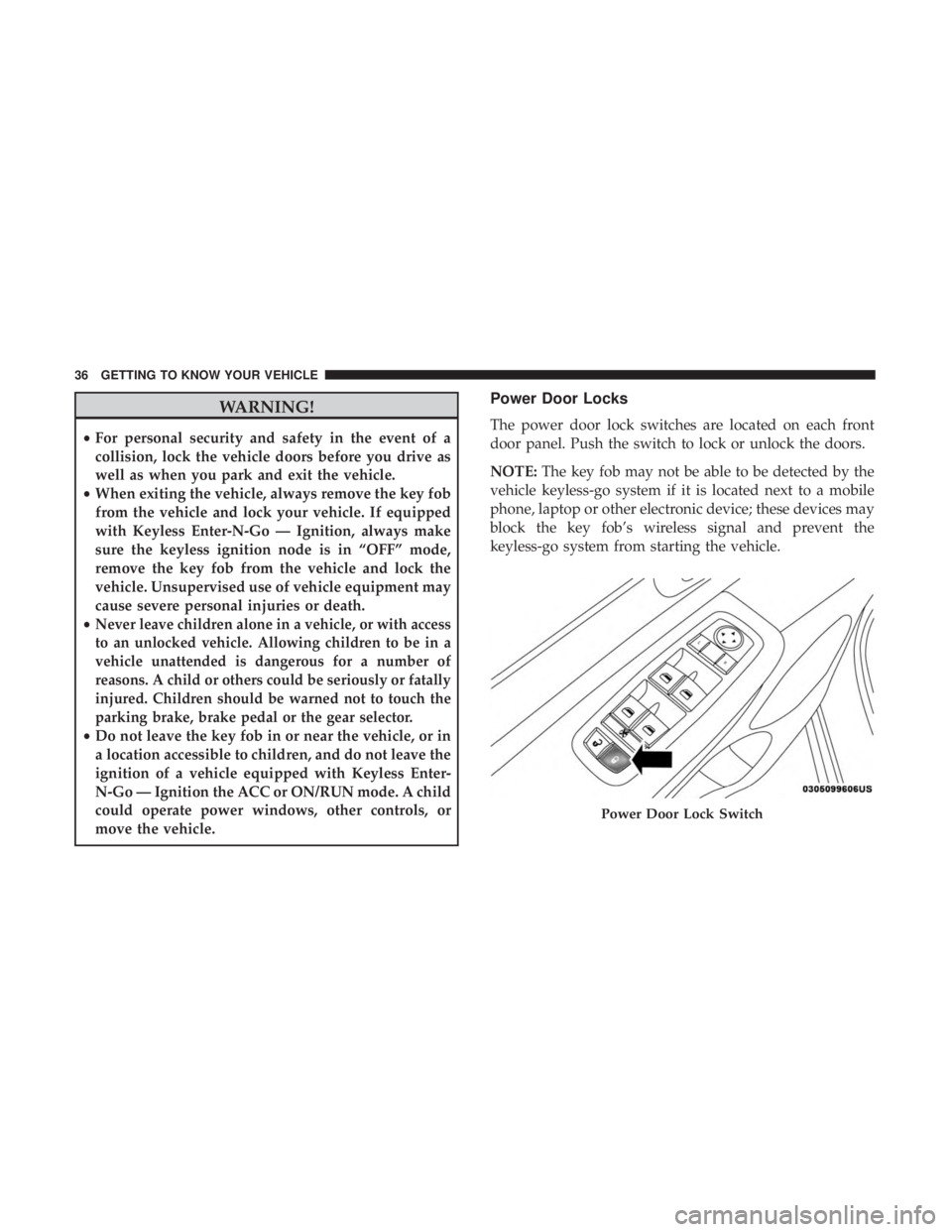
Power Door Locks
The power door lock switches are located on each front
door panel. Push the switch to lock or unlock the doors.
NOTE: The key fob may not be able to be detected by the
vehicle keyless-go system if it is located next to a mobile
phone, laptop or other electronic device; these devices may
block the key fob’s wireless signal and prevent the
keyless-go system from starting the vehicle.
Page 49 of 580
WARNING!
Do not ride with the seatback reclined so that the
shoulder belt is no longer resting against your chest. In
a collision you could slide under the seat belt, which
could result in serious injury or death.
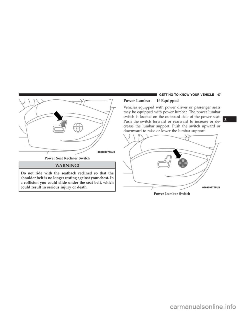
Power Lumbar — If Equipped
Vehicles equipped with power driver or passenger seats
may be equipped with power lumbar. The power lumbar
switch is located on the outboard side of the power seat.
Push the switch forward or rearward to increase or de-
crease the lumbar support. Push the switch upward or
downward to raise or lower the lumbar support.
Page 57 of 580
WARNING!(Continued)
•ALL the head restraints MUST be reinstalled in the
vehicle to properly protect the occupants. Follow the
re-installation instructions above prior to operating
the vehicle or occupying a seat.
• Do not place items over the top of the Reactive Head
Restraint, such as coats, seat covers or portable DVD
players. These items may interfere with the opera-
tion of the Reactive Head Restraint in the event of a
collision and could result in serious injury or death.
Rear Head Restraints
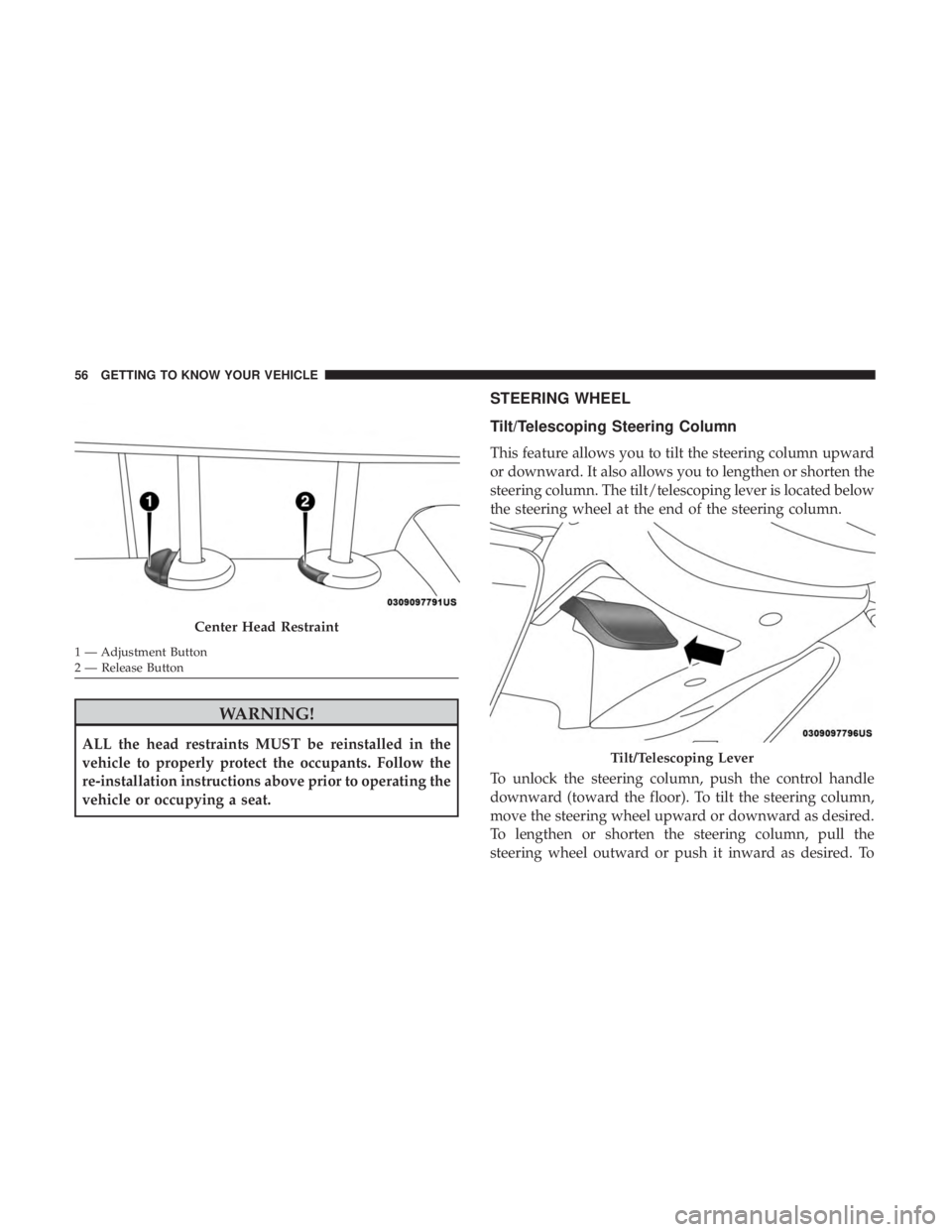
The rear outboard head restraints have three positions up,
mid and down. The center head restraint has only two
positions, up and down. When the center seat is being
occupied the head restraint should be in the raised posi-
tion. When there is no occupant in the center seat the head
restraint can be lowered for maximum visibility for the
driver.
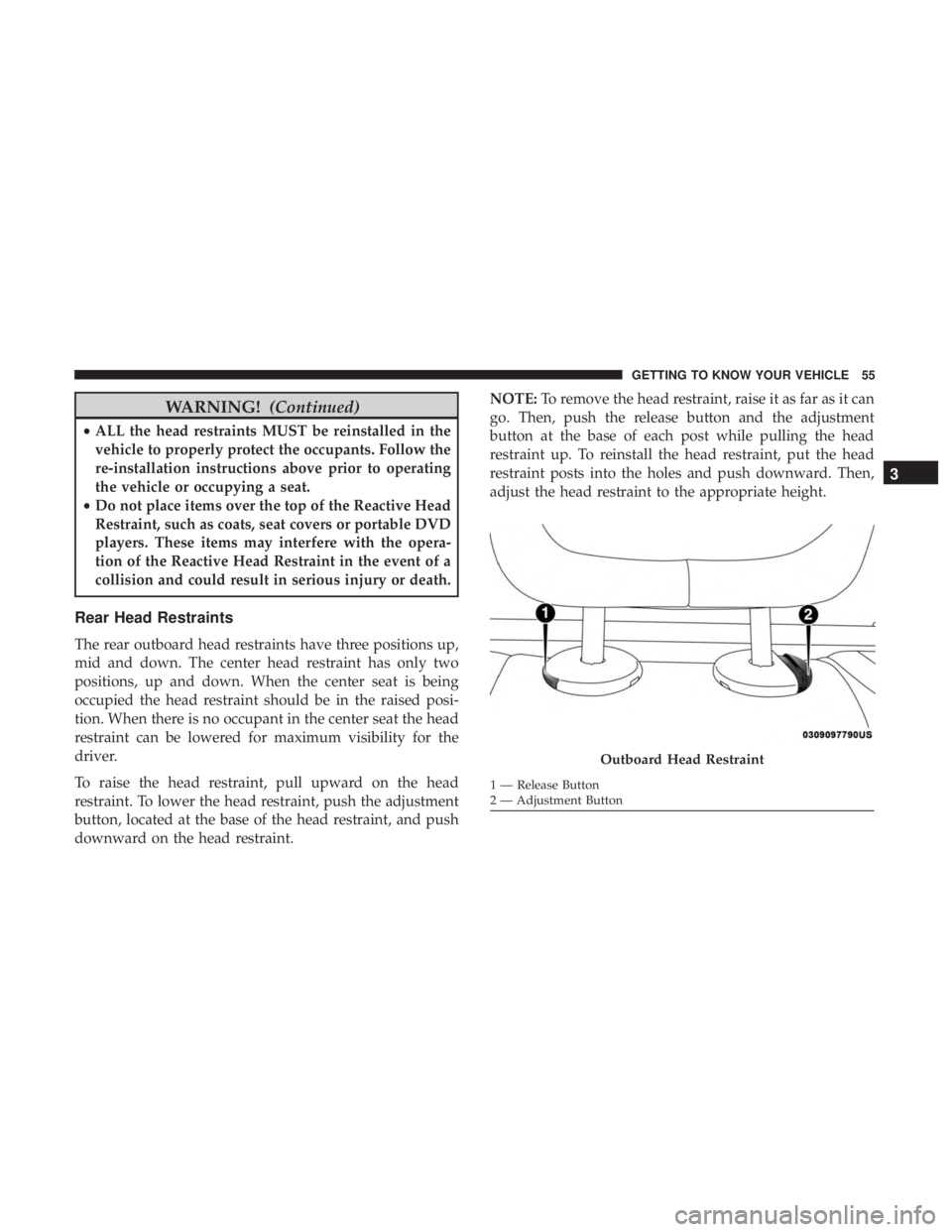
To raise the head restraint, pull upward on the head
restraint. To lower the head restraint, push the adjustment
button, located at the base of the head restraint, and push
downward on the head restraint. NOTE:
To remove the head restraint, raise it as far as it can
go. Then, push the release button and the adjustment
button at the base of each post while pulling the head
restraint up. To reinstall the head restraint, put the head
restraint posts into the holes and push downward. Then,
adjust the head restraint to the appropriate height.
Page 58 of 580
WARNING!
ALL the head restraints MUST be reinstalled in the
vehicle to properly protect the occupants. Follow the
re-installation instructions above prior to operating the
vehicle or occupying a seat.
STEERING WHEEL
Tilt/Telescoping Steering Column
This feature allows you to tilt the steering column upward
or downward. It also allows you to lengthen or shorten the
steering column. The tilt/telescoping lever is located below
the steering wheel at the end of the steering column.
To unlock the steering column, push the control handle
downward (toward the floor). To tilt the steering column,
move the steering wheel upward or downward as desired.
To lengthen or shorten the steering column, pull the
steering wheel outward or push it inward as desired. To
Page 60 of 580
WARNING!(Continued)
•Do not place anything on the steering wheel that
insulates against heat, such as a blanket or steering
wheel covers of any type and material. This may
cause the steering wheel heater to overheat.
MIRRORS
Inside Day/Night Mirror — If Equipped
The mirror head can be adjusted up, down, left, and right
for various drivers. The mirror should be adjusted to center
on the view through the rear window.
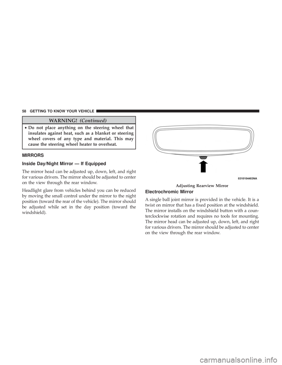
Headlight glare from vehicles behind you can be reduced
by moving the small control under the mirror to the night
position (toward the rear of the vehicle). The mirror should
be adjusted while set in the day position (toward the
windshield).
Electrochromic Mirror
A single ball joint mirror is provided in the vehicle. It is a
twist on mirror that has a fixed position at the windshield.
The mirror installs on the windshield button with a coun-
terclockwise rotation and requires no tools for mounting.
The mirror head can be adjusted up, down, left, and right
for various drivers. The mirror should be adjusted to center
on the view through the rear window.
Page 96 of 580
WARNING!
There is no anti-pinch protection when the window is
almost closed. To avoid personal injury be sure to clear
your arms, hands, fingers and all objects from the
window path before closing.
Reset Auto-Up
Should the Auto-Up feature stop working, the window
probably needs to be reset. To reset Auto-Up:
1. Pull the window switch up to close the window com-pletely and continue to hold the switch up for an
additional two seconds after the window is closed.
2. Push the window switch down firmly to open the window completely and continue to hold the switch
down for an additional two seconds after the window is
fully open.
Window Lockout Switch
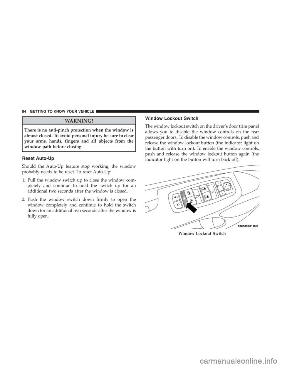
The window lockout switch on the driver’s door trim panel
allows you to disable the window controls on the rear
passenger doors. To disable the window controls, push and
release the window lockout button (the indicator light on
the button with turn on). To enable the window controls,
push and release the window lockout button again (the
indicator light on the button will turn back off).
Page 98 of 580
WARNING!(Continued)
children, can become entrapped by the power sun-
roof while operating the power sunroof switch. Such
entrapment may result in serious injury or death.
• In a collision, there is a greater risk of being thrown
from a vehicle with an open sunroof. You could also
be seriously injured or killed. Always fasten your
seat belt properly and make sure all passengers are
also properly secured.
• Do not allow small children to operate the sunroof.
Never allow your fingers, other body parts, or any
object, to project through the sunroof opening. In-
jury may result.
Opening Sunroof
Express
A comfort stop position and full open position are the
programmed automatic stops for the sunroof open posi-
tions. The comfort stop position has been optimized to
minimize wind buffeting.
Push the switch rearward and release it within one-half
second. The sunroof will open automatically to the comfort
stop position (if the sunshade is in the closed position when the operation is initiated the sunshade will automati-
cally open to the half open position prior to the sunroof
opening). Push the switch rearward and release it again,
the sunroof will open to the full open position and auto-
matically stop. This is called “Express Open”. During
Express Open operation, any movement of the sunroof
switch will stop the sunroof.
Manual Mode
A comfort stop position is a programmed automatic stop
for the sunroof open position. The comfort stop position
has been optimized to minimize wind buffeting.
To open the sunroof, push and hold the switch rearward.
The sunroof will stop automatically at the comfort stop
position (if the sunshade is in the closed position when the
operation is initiated the sunshade will automatically open
to the half open position prior to the sunroof opening).
Push and hold the switch rearward again, the sunroof will
open to the full open position and automatically stop. Any
release of the switch will stop the movement. The sunroof
and sunshade will remain in a partially opened condition
until the switch is pushed and held rearward again.
96 GETTING TO KNOW YOUR VEHICLE