warning light JEEP CHEROKEE TRAILHAWK 2018 User Guide
[x] Cancel search | Manufacturer: JEEP, Model Year: 2018, Model line: CHEROKEE TRAILHAWK, Model: JEEP CHEROKEE TRAILHAWK 2018Pages: 580, PDF Size: 5.68 MB
Page 198 of 580
The ORC contains a backup power supply system that may
deploy the air bag system even if the battery loses power or
it becomes disconnected prior to deployment.
The ORC turns on the Air Bag Warning Light in the
instrument panel for approximately four to eight seconds
for a self-check when the ignition switch is first in the
ON/RUN position. After the self-check, the Air Bag Warn-
ing Light will turn off. If the ORC detects a malfunction in
any part of the system, it turns on the Air Bag Warning
Light, either momentarily or continuously. A single chime
will sound to alert you if the light comes on again after
initial startup.
The ORC also includes diagnostics that will illuminate the
instrument panel Air Bag Warning Light if a malfunction is
detected that could affect the air bag system. The diagnos-
tics also record the nature of the malfunction. While the air
bag system is designed to be maintenance free, if any of the
following occurs, have an authorized dealer service the air
bag system immediately.
•The Air Bag Warning Light does not come on during the
four to eight seconds when the ignition switch is first in
the ON/RUN position.
• The Air Bag Warning Light remains on after the four to
eight-second interval. •
The Air Bag Warning Light comes on intermittently or
remains on while driving.
NOTE: If the speedometer, tachometer, or any engine
related gauges are not working, the Occupant Restraint
Controller (ORC) may also be disabled. In this condition
the air bags may not be ready to inflate for your protection.
Have an authorized dealer service the air bag system
immediately.
Page 199 of 580
panel. The Redundant Air Bag Warning Light will stay on
until the fault is cleared. In addition, a single chime will
sound to alert you that the Redundant Air Bag Warning
Light has come on and a fault has been detected. If the
Redundant Air Bag Warning Light comes on intermittently
or remains on while driving have an authorized dealer
service the vehicle immediately. For additional information
regarding the Redundant Air Bag Warning Light refer to
“Getting To Know Your Instrument Panel” section of this
manual.
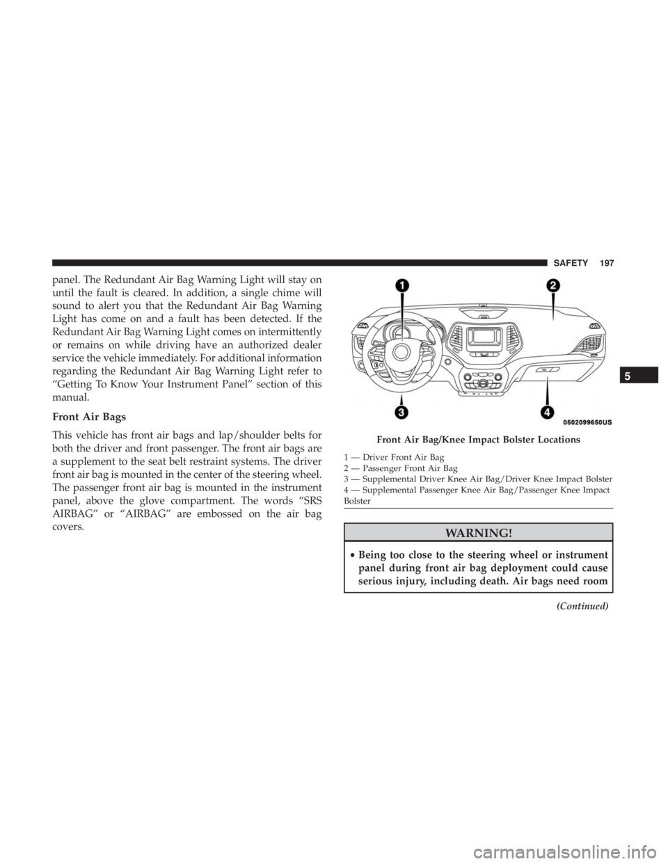
Front Air Bags
This vehicle has front air bags and lap/shoulder belts for
both the driver and front passenger. The front air bags are
a supplement to the seat belt restraint systems. The driver
front air bag is mounted in the center of the steering wheel.
The passenger front air bag is mounted in the instrument
panel, above the glove compartment. The words “SRS
AIRBAG” or “AIRBAG” are embossed on the air bag
covers.
Page 209 of 580

WARNING!
•Do not drill, cut, or tamper with the knee impact
bolsters in any way.
• Do not mount any accessories to the knee impact
bolsters such as alarm lights, stereos, citizen band
radios, etc.
Supplemental Driver And Front Passenger Knee Air
Bags
This vehicle is equipped with a Supplemental Driver Knee
Air Bag mounted in the instrument panel below the steering
column and a Supplemental Passenger Knee Air Bag
mounted in the instrument panel below the glove compart-
ment. The Supplemental Knee Air Bags provide enhanced
protection during a frontal impact by working together with
the seat belts, pretensioners, and front air bags.
Supplemental Side Air Bags
Supplemental Seat-Mounted Side Air Bags (SABs)
This vehicle is equipped with Supplemental Seat-Mounted
Side Air Bags (SABs). Supplemental Seat-Mounted Side Air Bags (SABs) are
located in the outboard side of the front seats and rear (in
vehicles equipped with outboard rear seat SABs) seats. The
SABs are marked with “SRS AIRBAG” or “AIRBAG” on a
label or on the seat trim on the outboard side of the seats.
The SABs may help to reduce the risk of occupant injury
during certain side impacts, in addition to the injury
reduction potential provided by the seat belts and body
structure.
Page 238 of 580
WARNING!(Continued)
•If the vehicle carpet has been removed and re-
installed, always properly attach carpet to the floor
and check the floor mat fasteners are secure to the
vehicle carpet. Fully depress each pedal to check for
interference with the accelerator, brake, or clutch
pedals then re-install the floor mats.
• It is recommended to only use mild soap and water
to clean your floor mats. After cleaning, always check
your floor mat has been properly installed and is
secured to your vehicle using the floor mat fasteners
by lightly pulling mat.
Periodic Safety Checks You Should Make Outside
The Vehicle
Tires
Examine tires for excessive tread wear and uneven wear
patterns. Check for stones, nails, glass, or other objects
lodged in the tread or sidewall. Inspect the tread for cuts
and cracks. Inspect sidewalls for cuts, cracks, and bulges.
Check the wheel nuts for tightness. Check the tires (includ-
ing spare) for proper cold inflation pressure.
Lights
Have someone observe the operation of brake lights and
exterior lights while you work the controls. Check turn
signal and high beam indicator lights on the instrument
panel.
Door Latches
Check for proper closing, latching, and locking.
Fluid Leaks
Check area under the vehicle after overnight parking for
fuel, coolant, oil, or other fluid leaks. Also, if gasoline
fumes are detected or if fuel, or brake fluid leaks are
suspected. The cause should be located and corrected
immediately.
236 SAFETY
Page 262 of 580
WARNING!
You or others could be injured or killed if you leave the
vehicle unattended with the power transfer unit in the
NEUTRAL (N) position without first fully engaging
the parking brake. The NEUTRAL (N) position disen-
gages both the front and rear driveshafts from the
powertrain and will allow the vehicle to roll, even if
the transmission is in PARK. The parking brake
should always be applied when the driver is not in the
vehicle.
4WD LOW
This range is for low speed four-wheel drive. It provides an
additional gear reduction which allows for increased
torque to be delivered to both the front and rear wheels
while providing maximum pulling power for loose, slip-
pery road surfaces only. Do not exceed 25 mph (40 km/h).
NOTE:Refer to “Selec-Terrain — If Equipped” for further
information on the various positions and their intended
usages.
Shifting Procedures
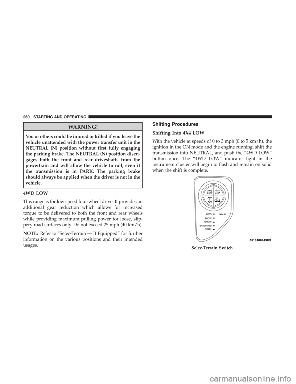
Shifting Into 4X4 LOW
With the vehicle at speeds of 0 to 3 mph (0 to 5 km/h), the
ignition in the ON mode and the engine running, shift the
transmission into NEUTRAL, and push the “4WD LOW”
button once. The “4WD LOW” indicator light in the
instrument cluster will begin to flash and remain on solid
when the shift is complete.
Page 376 of 580
WARNING!(Continued)
can cause the 9-1-1 Call system to fail, never add
aftermarket equipment (e.g., two-way mobile radio,
CB radio, data recorder, etc.) to your vehicle’s electri-
cal system or modify the antennas on your vehicle.
IF YOUR VEHICLE LOSES BATTERY POWER FOR
ANY REASON (INCLUDING DURING OR AFTER
AN ACCIDENT), THE UCONNECT FEATURES,
APPS AND SERVICES, AMONG OTHERS, WILL
NOT OPERATE.
• Modifications to any part of the 9-1-1 Call system
could cause the air bag system to fail when you need
it. You could be injured if the air bag system is not
there to help protect you.
9-1-1 Call System Limitations
Vehicles sold in Canada and Mexico DO NOThave 9-1-1
Call system capabilities.
9-1-1 or other emergency line operators in Canada and
Mexico may not answer or respond to 9-1-1 system calls.
If the 9-1-1 Call system detects a malfunction, any of the
following may occur at the time the malfunction is de-
tected, and at the beginning of each ignition cycle: •
The Rearview Mirror light located between the ASSIST
and 9-1-1 buttons will continuously be illuminated red.
• The Device Screen will display the following message
“Vehicle device requires service. Please contact your
dealer.”
• An In-Vehicle Audio message will state “Vehicle device
requires service. Please contact your dealer.”
Page 398 of 580
NOTE:•For vehicles so equipped, do not attempt to install a
center cap or wheel cover on the compact spare.
• Refer to “Compact Spare Tire” and to “Limited-Use
Spare” under “Tires—General Information” in “Servic-
ing And Maintenance” for additional warnings, cau-
tions, and information about the spare tire, its use, and
operation.
9. Install the wheel bolts with the threaded end of the wheel bolt toward the wheel. Lightly tighten the wheel
bolts.
Page 478 of 580
WARNING!
The temperature grade for this tire is established for
a tire that is properly inflated and not overloaded.
Excessive speed, under-inflation, or excessive load-
ing, either separately or in combination, can cause
heat buildup and possible tire failure.
STORING THE VEHICLE
If the vehicle should remain stationary for more than a
month, observe the following precautions:
• Park your vehicle in a covered, dry and possibly airy
location the windows open slightly.
• Check that the Electric Park Brake is not engaged.
• Disconnect the negative (-) terminal from the battery
post and be sure that the battery is fully charged. During
storage check battery charge quarterly.
• If you do not disconnect the battery from the electrical
system, check the battery charge every 30 days.
• Clean and protect the painted parts by applying protec-
tive waxes. •
Clean and protect polished metal parts by applying
protective waxes.
• Apply talcum powder to the front and rear wiper blades
and leave raised from the glass.
• Cover the vehicle with an appropriate cover taking care
not to damage the painted surface by dragging across
dirty surfaces. Do not use plastic sheeting which will not
allow the evaporation of moisture present on the surface
of the vehicle.
• Inflate the tires at a pressure of +7.25 psi (+0.5 bar)
higher than recommended on the tire placard and check
it periodically.
• Do not drain the engine cooling system.
• Whenever you leave the vehicle is stationary for two
weeks or more, run idle the engine for approximately
five minutes, with the air conditioning system on and
high fan speed. This will ensure a proper lubrication of
the system, thus minimizing the possibility of damage to
the compressor when the vehicle is put back into opera-
tion.
476 SERVICING AND MAINTENANCE