brakes JEEP CHEROKEE TRAILHAWK 2019 Owners Manual
[x] Cancel search | Manufacturer: JEEP, Model Year: 2019, Model line: CHEROKEE TRAILHAWK, Model: JEEP CHEROKEE TRAILHAWK 2019Pages: 638, PDF Size: 6.16 MB
Page 163 of 638
WARNING!(Continued)
•The capabilities of an ABS equipped vehicle must
never be exploited in a reckless or dangerous manner
that could jeopardize the user ’s safety or the safety of
others.
ABS is designed to function with the OEM tires. Modifica-
tion may result in degraded ABS performance.
Anti-Lock Brake Warning Light
The yellow “Anti-Lock Brake Warning Light” will turn on
when the ignition is turned to the ON/RUN mode and
may stay on for as long as four seconds.
If the “Anti-Lock Brake Warning Light” remains on or
comes on while driving, it indicates that the anti-lock
portion of the brake system is not functioning and that
service is required. However, the conventional brake sys-
tem will continue to operate normally if the “Anti-Lock
Brake Warning Light” is on.
If the “Anti-Lock Brake Warning Light” is on, the brake
system should be serviced as soon as possible to restore the
benefits of anti-lock brakes. If the “Anti-Lock Brake Warning
Light” does not come on when the ignition is turned to the
ON/RUN mode, have the light repaired as soon as possible.
Electronic Brake Control System
Your vehicle is equipped with an advanced Electronic
Brake Control system (EBC). This system includes Elec-
tronic Brake Force Distribution (EBD), Anti-Lock Brake
System (ABS), Brake Assist System (BAS), Hill Start Assist
(HSA), Traction Control System (TCS), Electronic Stability
Control (ESC), and Electronic Roll Mitigation (ERM). These
systems work together to enhance both vehicle stability
and control in various driving conditions.
Your vehicle may also be equipped with Trailer Sway
Control (TSC), Ready Alert Braking (RAB), Rain Brake
Support (RBS), Dynamic Steering Torque (DST), Hill De-
scent Control (HDC), and Selec-Speed Control (SSC).
Electronic Brake Force Distribution (EBD)
This function manages the distribution of the braking
torque between the front and rear axles by limiting braking
pressure to the rear axle. This is done to prevent overslip of
the rear wheels to avoid vehicle instability, and to prevent
the rear axle from entering ABS before the front axle.
Brake System Warning Light
The red “Brake System Warning Light” will turn on when
the ignition is turned to the ON/RUN mode and may stay
on for as long as four seconds.
5
SAFETY 161
Page 164 of 638
If the “Brake System Warning Light” remains on or comes
on while driving, it indicates that the brake system is not
functioning properly and that immediate service is re-
quired. If the “Brake System Warning Light” does not come
on when the ignition is turned to the ON/RUN mode, have
the light repaired as soon as possible.
Brake Assist System (BAS)
The BAS is designed to optimize the vehicle’s braking
capability during emergency braking maneuvers. The sys-
tem detects an emergency braking situation by sensing the
rate and amount of brake application and then applies
optimum pressure to the brakes. This can help reduce
braking distances. The BAS complements the anti-lock
brake system (ABS). Applying the brakes very quickly
results in the best BAS assistance. To receive the benefit of
the system, you must apply continuous braking pressure
during the stopping sequence, (do not “pump” the brakes).
Do not reduce brake pedal pressure unless braking is no
longer desired. Once the brake pedal is released, the BAS is
deactivated.
Page 175 of 638
WARNING!
HDC is only intended to assist the driver in controlling
vehicle speed when descending hills. The driver must
remain attentive to the driving conditions and is re-
sponsible for maintaining a safe vehicle speed.
Selec Speed Control (SSC) — If Equipped
SSC is intended for off road driving in 4WD Low Range
only. SSC maintains vehicle speed by actively controlling
engine torque and brakes.
SSC has three states:
1. Off (feature is not enabled and will not activate).
2. Enabled (feature is enabled and ready but activationconditions are not met, or driver is actively overriding
with brake or throttle application).
3. Active (feature is enabled and actively controlling ve- hicle speed).
Enabling SSC
SSC is enabled by pushing the SSC switch, but the follow-
ing conditions must also be met to enable SSC:
• Driveline is in 4WD Low Range. •
Vehicle speed is below 5 mph (8 km/h).
• Parking brake is released.
• Driver door is closed.
• Driver is not applying throttle.
Activating SSC
Once SSC is enabled it will activate automatically once the
following conditions are met:
• Driver releases throttle.
• Driver releases brake.
• Transmission is in any selection other than P.
• Vehicle speed is below 20 mph (32 km/h).
The set speed for SSC is selectable by the driver, and can be
adjusted by using the gear shift +/-. Additionally, the SSC
set speed may be reduced when climbing a grade and the
level of set speed reduction depends on the magnitude of
grade. The following summarizes the SSC set speeds:
SSC Target Set Speeds
• 1st = .6 mph (1 km/h)
• 2nd = 1.2 mph (2 km/h)
5
SAFETY 173
Page 177 of 638
Disabling SSC
SSC will deactivate and be disabled if any of the following
conditions occur:
•The driver pushes the SSC switch.
• The driveline is shifted out of 4WD Low Range.
• The parking brake is applied.
• Driver door opens.
• The vehicle is driven greater than 20 mph (32 km/h) for
greater than 70 seconds.
• The vehicle is driven greater than 40 mph (64 km/h)
(SSC exits immediately).
Feedback To The Driver:
The instrument cluster has an SSC icon and the SSC switch
has an LED which offer feedback to the driver about the
state SSC is in.
• The cluster icon and switch lamp will illuminate and
remain on solid when SSC is enabled or activated. This
is the normal operating condition for SSC. •
The cluster icon and switch lamp will flash for several
seconds then extinguish when the driver pushes the SSC
switch but enable conditions are not met.
• The cluster icon and switch lamp will flash for several
seconds then extinguish when SSC disables due to
excess speed.
• The cluster icon and switch lamp will flash then extin-
guish when SSC deactivates due to overheated brakes.
Page 186 of 638
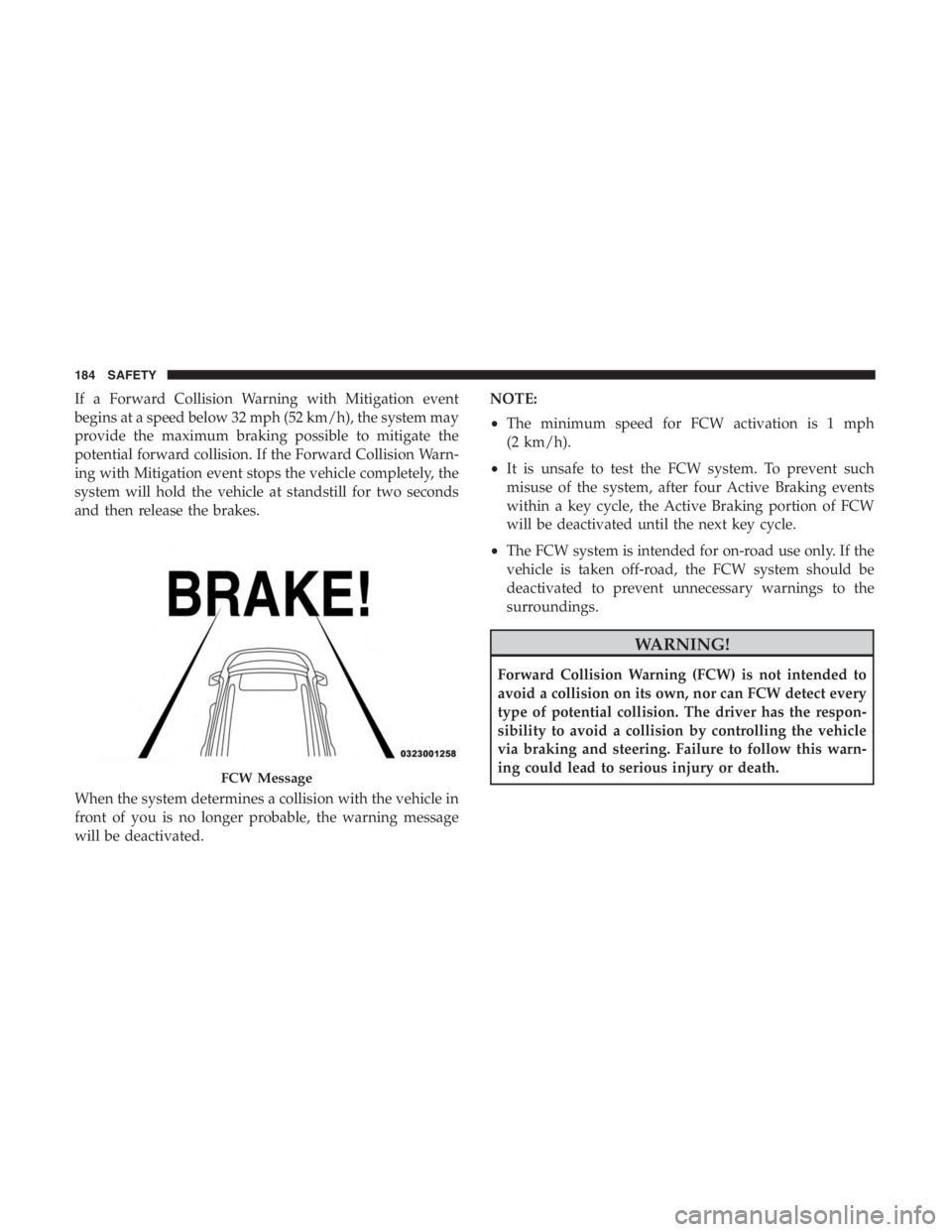
If a Forward Collision Warning with Mitigation event
begins at a speed below 32 mph (52 km/h), the system may
provide the maximum braking possible to mitigate the
potential forward collision. If the Forward Collision Warn-
ing with Mitigation event stops the vehicle completely, the
system will hold the vehicle at standstill for two seconds
and then release the brakes.
When the system determines a collision with the vehicle in
front of you is no longer probable, the warning message
will be deactivated.NOTE:
•
The minimum speed for FCW activation is 1 mph
(2 km/h).
• It is unsafe to test the FCW system. To prevent such
misuse of the system, after four Active Braking events
within a key cycle, the Active Braking portion of FCW
will be deactivated until the next key cycle.
• The FCW system is intended for on-road use only. If the
vehicle is taken off-road, the FCW system should be
deactivated to prevent unnecessary warnings to the
surroundings.
FCW Message
184 SAFETY
Page 266 of 638
•The seat belt is unbuckled.
• The driver door is open.
SafeHold can be temporarily bypassed by pushing the
Electric Park Brake Switch while the driver door is open.
Once manually bypassed, SafeHold will be enabled again
once the vehicle reaches 12 mph (20 km/h) or the ignition
is turned to the OFF position and back to ON again.
Brake Service Mode
We recommend having your brakes serviced by your
authorized dealer. You should only make repairs for which
you have the knowledge and the right equipment. You
should only enter Brake Service Mode during brake ser-
vice.
When servicing your rear brakes, it may be necessary for
you or your technician to push the rear piston into the rear
caliper bore. With the electric park brake system, this can
only be done after retracting the Electric Park Brake
actuator. Fortunately, actuator retraction can be done easily
by entering the Brake Service Mode through the Uconnect
Settings in your vehicle. This menu based system will
guide you through the steps necessary to retract the EPB
actuator in order to perform rear brake service. Service Mode has requirements that must be met in order
to be activated:
•
The vehicle must be at a standstill.
• The park brake must be unapplied.
• The transmission must be in PARK or NEUTRAL.
While in service mode, the Electric Park Brake fault lamp
will flash continuously while the ignition is ON.
When brake service work is complete, the following steps
must be followed to reset the park brake system to normal
operation:
• Ensure the vehicle is at a standstill.
• Press the brake pedal with moderate force.
• Apply the Electric Park Brake Switch.
Page 268 of 638
WARNING!(Continued)
•Do not leave the key fob in or near the vehicle (or in
a location accessible to children), and do not leave
the ignition (in a vehicle equipped with Keyless
Enter-N-Go) in the ACC or ON/RUN mode. A child
could operate power windows, other controls, or
move the vehicle.
CAUTION!
Damage to the transmission may occur if the following
precautions are not observed:
•Shift into or out of PARK or REVERSE only after the
vehicle has come to a complete stop.
• Do not shift between PARK, REVERSE, NEUTRAL,
or DRIVE when the engine is above idle speed.
• Before shifting into any gear, make sure your foot is
firmly pressing the brake pedal.
NOTE: You must press and hold the brake pedal while
shifting out of PARK.
Key Ignition Park Interlock
This vehicle is equipped with a Key Ignition Park Interlock
which requires the transmission to be in PARK before the
ignition can be turned to the LOCK/OFF (key removal)
position. The key fob can only be removed from the
ignition when the ignition is in the LOCK/OFF position,
and the transmission is locked in PARK whenever the
ignition is in the LOCK/OFF position.
Brake/Transmission Shift Interlock System
This vehicle is equipped with a Brake Transmission Shift
Interlock system (BTSI) that holds the transmission gear
selector in PARK unless the brakes are applied. To shift the
transmission out of PARK, the ignition must be in the
ON/RUN mode (engine running or not) and the brake
pedal must be pressed.
The brake pedal must also be pressed to shift from NEU-
TRAL into DRIVE or REVERSE when the vehicle is
stopped or moving at low speeds.
266 STARTING AND OPERATING
Page 302 of 638
ACC Operation At Stop
If the ACC system brings your vehicle to a standstill while
following a target vehicle, if the target vehicle starts
moving within two seconds of your vehicle coming to a
standstill, your vehicle will resume motion without the
need for any driver action.
If the target vehicle does not start moving within two
seconds of your vehicle coming to a standstill, the driver
will either have to push the RES button, or press the
accelerator to reengage the ACC to the existing set speed.
NOTE:After the ACC system holds your vehicle at a
standstill for approximately 3 consecutive minutes, the
parking brake system will be activated and the ACC
system will be cancelled.
While ACC with stop is holding your vehicle at a standstill,
if the driver seatbelt is unbuckled or the driver door is
opened, the ACC with stop system will cancel and the
brakes will ramp-out. Driver intervention will be required
at this moment.
Page 372 of 638
WARNING!
It is important that you do not exceed the maximum
front or rear GAWR. A dangerous driving condition
can result if either rating is exceeded. You could lose
control of the vehicle and have a collision.
Tongue Weight (TW)
The tongue weight is the downward force exerted on the
hitch ball by the trailer. You must consider this as part of
the load on your vehicle.
Trailer Frontal Area
The frontal area is the maximum height multiplied by the
maximum width of the front of a trailer.
Trailer Sway Control
The trailer sway control can be a mechanical telescoping
link that can be installed between the hitch receiver and the
trailer tongue that typically provides adjustable friction
associated with the telescoping motion to dampen any
unwanted trailer swaying motions while traveling.If equipped, the electronic Trailer Sway Control (TSC)
recognizes a swaying trailer and automatically applies
individual wheel brakes and/or reduces engine power to
attempt to eliminate the trailer sway.
Weight-Carrying Hitch
A weight-carrying hitch supports the trailer tongue weight,
just as if it were luggage located at a hitch ball or some
other connecting point of the vehicle. These kinds of
hitches are the most popular on the market today and they
are commonly used to tow small and medium sized
trailers.
Weight-Distributing Hitch
A weight-distributing system works by applying leverage
through spring (load) bars. They are typically used for
heavier loads to distribute trailer tongue weight to the tow
vehicle’s front axle and the trailer axle(s). When used in
accordance with the manufacturer’s directions, it provides
for a more level ride, offering more consistent steering and
brake control thereby enhancing towing safety. The addi-
tion of a friction/hydraulic sway control also dampens
sway caused by traffic and crosswinds and contributes
positively to tow vehicle and trailer stability. Trailer sway
control and a weight distributing (load equalizing) hitch
are recommended for heavier Tongue Weights (TW) and
370 STARTING AND OPERATING
Page 377 of 638
CAUTION!(Continued)
not make starts at full throttle. This helps the engine
and other parts of the vehicle wear in at the heavier
loads.
Towing Requirements — Tires
•Do not attempt to tow a trailer while using a compact
spare tire.
• Do not drive more than 50 mph (80 km/h) when towing
while using a full size spare tire.
• Proper tire inflation pressures are essential to the safe
and satisfactory operation of your vehicle. Refer to
“Tires” in “Servicing And Maintenance” for proper tire
inflation procedures.
• Check the trailer tires for proper tire inflation pressures
before trailer usage.
• Check for signs of tire wear or visible tire damage before
towing a trailer. Refer to “Tires” in “Servicing And
Maintenance” for the proper inspection procedure.
•
When replacing tires, refer to “Tires” in “Servicing And
Maintenance” for the proper tire replacement procedures.
Replacing tires with a higher load carrying capacity will
not increase the vehicle’s GVWR and GAWR limits.
Towing Requirements — Trailer Brakes
• Do not interconnect the hydraulic brake system or
vacuum system of your vehicle with that of the trailer.
This could cause inadequate braking and possible per-
sonal injury.
• An electronically actuated trailer brake controller is
required when towing a trailer with electronically actu-
ated brakes. When towing a trailer equipped with a
hydraulic surge actuated brake system, an electronic
brake controller is not required.
• Trailer brakes are recommended for trailers over
1,000 lbs (453 kg) and required for trailers in excess of
2,000 lbs (907 kg).