change wheel JEEP CJ 1953 User Guide
[x] Cancel search | Manufacturer: JEEP, Model Year: 1953, Model line: CJ, Model: JEEP CJ 1953Pages: 376, PDF Size: 19.96 MB
Page 90 of 376
DAUNTLESS
V-6
ENGINE
Note:
The rib on
edge
of cap and the conical
boss
on web of connecting rod must be toward
rear
of
engine
in all connecting rod assemblies of left
cyl
inder
bank and toward front of
engine
in all connecting rod assemblies of right cylinder bank.
Dl-50.
Oil
Pump Intake
and
Screen Cleaning
a.
Pry screen from housing and examine for clog
ging due to deposit of sludge or other foreign
material.
b.
Clean
the screen and housing thoroughly in sol
vent; dry with compressed air.
c.
Install
screen in housing.
Dl-51.
Oil Pan Cleaning and Inspection
Inspect
the oil pan for corrosion, dents, leaks, and
other damage. Inspect its mounting flange carefully
for damage or distortion to be certain that it
will
give
a
good
seal.
Dl-52.
Flywheel Cleaning
and
Inspection
Clean
the flywheel with suitable cleaning solvent;
dry
with compressed air. Inspect clutch face for
burned
or scuffed condition and for rivet grooves.
Inspection
for run out or improper mounting is de
scribed
in installation procedure.
Inspect
teeth
of the flywheel
ring
gear for
burrs,
nicks,
and minor distortion. If necessary and pos
sible, use a small emery wheel to remove
burrs
and
reshape teeth. If gear
teeth
are broken,
cracked,
seriously
burred
or deformed, the
ring
gear must be replaced.
Dl-53.
Ring Gear Replacement
a.
Drill
a
hole
between
two
ring
gear teeth; then
split
the gear with a cold chisel. Be careful not to
damage
ring
gear shoulder or seat surfaces of fly
wheel.
b.
Polish several
spots
on the new
ring
gear to be
installed.
With
a hot plate or slowly moving torch,
heat the new
ring
gear until polished
spots
become
blue, about
600°F.
[312°C.].
Caution:
Do not heat the
ring
gear to a temperature
greater than
800°F.
[424°C.].
Excessive heat
will
destroy heat treatment given to
ring
gear during
manufacture.
c.
Quickly
install
ring
gear on flywheel. Chamfered
edge
of
ring
gear must be toward
ring
gear shoulder
of flywheel. Be certain that
ring
gear is seated prop
erly.
Allow
ring
gear to cool slowly, so that it
will
be held tightly in place.
Dl-54.
Flywheel Housing Cleaning and Inspection
Both
flywheel and clutch are enclosed by a fly
wheel housing. Its front surface is bolted to the
engine
cylinder block, and its
rear
surface acts as
front
support to the transmission.
Clean
the fly wheel housing with a suitable cleaning solvent; dry
with
compressed air. Inspect front and
rear
surfaces
for distortion and improper alignment with each
other;
these
planes must be
parallel
to assure
proper
alignment
between
engine
and transmission.
Dl-55.
Camshaft Cleaning
and
Inspection
Clean
both camshaft and camshaft bearing surfaces
with
a suitable cleaning solvent; dry with com
pressed air.
Note:
The steel-backed babbitt-lined camshaft
bearings are pressed into the crankcase.
From
front
to
rear,
each bearing is .030" [0,76 mm.] smaller
in
diameter than the preceding bearing.
From
front
to
rear,
each camshaft
journal
is correspondingly
smaller
in diameter.
The
camshaft bearings must be line reamed to
proper
diameter after being pressed into crankcase.
Since
this operation requires special reaming equip
ment, the original bearings should be retained un
less
they are severly damaged. Slightly scored cam
shaft bearings are satisfactory if the surfaces of camshaft journals are polished, bearings are
polished to remove
burrs,
and
radial
clearance
between
camshaft and bearings is within .0015"
to .004" [0,038 a 0,102 mm.].
Dl-56.
Valve Lifter
and
Push
Rod
Cleaning and Inspection
a.
Examine the cam contact surface at lower end of each valve lifter body. If surface is excessively
worn,
galled, or otherwise damaged, discard the
valve lifter. Also examine the mating camshaft
lobe
for excessive wear or damage.
b.
Disassemble one or two valve lifters, as de
scribed
below, and inspect them for
dirt
or
varnish.
If
they are dirty or have a varnish deposit, clean
and
inspect all twelve valve lifters. Otherwise,
service
only
those
valve lifters which do not operate
properly.
c.
To disassemble each valve lifter, depress the
push
rod seat with a push rod, and remove the
plunger retainer from the valve lifter body with
a
retainer remover. Remove push rod seat and
plunger from valve lifter body. If plunger sticks
in
valve lifter body, place body in large end of
a
plunger remover tool, with plunger downward.
While
holding lifter with thumb, rap the open end
of remover against a block of wood with just enough force to jar the plunger from body. Refer to
Figs.
Dl-20, Dl-22 and Dl-23.
d.
Drain
oil from valve lifter and remove the check
valve retainer,
ball,
valve spring, and plunger
spring.
e. Keep all parts of each valve lifter separated
during
part cleaning and inspection. The valve
lifter
body and plunger are selectively fitted to each other and must not be interchanged with parts
of other valve lifters.
f. Rinse all valve lifter parts in kerosene to remove as much oil as possible.
This
will
reduce contamina
tion of the cleaning solvent. Immerse all parts in cleaning solvent for approximately one hour. The
time required
will
depend on varnish
deposits
and
effectiveness
of the solvent. After the varnish has
dissolved or has
softened
sufficiently to permit re
moval
by wiping, allow parts to
drain.
Varnish
can
then be cleaned from the valve lifter body
with
a
brush.
Rinse the parts in kerosene to dissolve 90
Page 216 of 376
ELECTRICAL
SYSTEM
14385
FIG.
H-61—BACK-UP
LIGHT
1—
Snap
Ring
2—
Lens
3—
Gasket
4—
Bulb
5—
Housing
and
Cable
On
late production
T14A
transmissions the backup
light switch is threaded into the right
rear
corner
of the cover housing and is activated by the move
ment of the reverse shift
rail.
The
backup light switch is not serviceable and
must be replaced if defective.
Bulbs
can be replaced by removing the snap
ring,
lens and gasket from the assembly.
H-136.
License Plate
Light
On
CJ-5A,
CJ-6A
and current production vehicles
the license plate light is attached to the tailgate
and
is of the swing-type design to enable the
license plate to be visible when the tailgate is in
the down psoition. The bulb can be changed by
removing
the clear plastic lens. On early production
vehicles the license plate light is integral with the
tail
light assembly.
H-137.
Horn
The
horn is mounted under the hood on the
left
front
fender. The horn is sounded by pressing the
button located at the top center of the steering
wheel.
To
remove the horn wire, disconnect the wire at
the snap connection at the base of the steering
column.
Pull
off the rubber horn button cap and
the brass contact cap from the steering wheel nut.
This
will
expose
the contact tip of the horn wire.
Pull
the wire out of the steering column from the top. Refer to Fig. H-62.
H-13S.
Directional
Signals
Fig.
H-63 shows the
wiring
of a
composite
direction
al
signal
circuit.
The most frequent causes of
failure
in
the directional signal system are
loose
connec
tions and burned-out bulbs. A flashing rate
approximately
twice the normal rate usually in
dicates a burned-out bulb in the
circuit.
11087
FIG.
H-62—HORN
BUTTON 1—
Cap
2— Nut
3—
Horn
Button
Spring
Cup 4—
Ferrule
5—
Horn
Cable
6—
Contact
Disc
7—
Steering
Wheel
8—
Cup
9—
Bearing
Spring
Seat
10—
Steering
Column
11—
Tube
12—
Bearing
13—
Bearing
Spring
14—
Horn
Button
Spring
15—
Retainer
Spring
When
trouble in the signal switch is suspected it
is advisable to make the following
test
to definitely
locate the trouble before
going
to the effort of
removing
the signal switch. If, for example, the
right
rear
stop
light and right front parking light
are
inoperative and switch failure is indicated, first put the control lever in neutral position.
Then
disconnect the wire to the right side
circuit
and
touch it to or bridge it to the
"L"
terminal, thus
by-passing the signal switch. If the right side cir- 10609
FIG.
H-63—DIRECTIONAL SIGNAL
CIRCUIT
1—
Flasher
2—
Ignition
Switch
3—
Control
4—
Light
Switch
5— Stop
Light
Switch
216
Page 282 of 376
FRONT
AXLE
FIG.
M-l
1—FRONT
STEERING
KNUCKLE
(With
Spicer Universal Joint)
1—
Wheel
Hub Cap
2—
Driving
Flange Cap Screw
3—
Axle
Shaft Drive Flange Gasket 4—
Wheel
Bearing Cup
5—
Front
Wheel Spindle
6—
Brake
Drum
7—
Front
Brake
Cylinder
8—
Brake
Backing Plate
9—
Pivot
Pin Bearing Cap
10—
Pivot
Pin Bearing Cap Nut
11—
Pivot
Pin 12—
Pivot
Bearing Adjusting Shims
13—
Pivot
Pin Cone and Rollers
14—
Steering
Knuckle
Oil Seal 15—
Front
Axle Universal Joint
16—
Thrust
Washer
17—
Brake
Backing Plate Screw
18—
Brake
Shoe and
Lining
19—
Hub
Oil Seal
20—
Wheel
Hub Bolt Nut
21—
Wheel
Bearing Cone and Rollers 22—
Wheel
Bearing Washer
23—
Wheel
Bearing Retaining Nut
24—
Wheel
Adjusting Nut
Lock
Washer
25—
Wheel
Bearing Retaining Nut
26—
Snap
Ring
c.
Install
the wheel bearing spindle and bushing.
d.
Install
brake backing plate.
e.
Grease and assemble wheel bearings and oil
seal.
Install
the wheel hub and drum on the wheel
bearing
spindle.
Install
the wheel bearing washer
and
adjusting nut. Tighten nut with
Wrench
W-144
as shown in
Fig.
M-5, until there is a slight drag on the bearings when the hub is turned.
Then
back off approximately one-sixth of a
turn.
Install
lock
washer
and nut, tightening nut
into
place, and then bend lip of lock washer over on the locknut.
f.
Install
drive
flange
and gasket on hub and attach
with
six cap screws and lock washers.
Install
snap
ring
on outer end of axle shaft.
g.
Install
hub cap.
h.
Install
the wheel, lug nuts, and wheel disc.
i.
If
tube
was installed with axle assembly on
vehicle, check front wheel alignment (Section O),
bleed brakes (Section P), and lubricate front axle
universal
joints (Section B).
M-12.
FRONT
AXLE
INSTALLATION
To
install the front axle, reverse the procedures described in
Par.
M-4 and then perform the follow
ing operations:
a.
Torque spring clip plate (U-bolt) nuts securing the axle to the front springs, (see Par. M-4).
b.
Adjust and bleed the brakes (see Section P).
c.
Check
axle lubricant level and
fill
as necessary, (see Section B).
d.
Check
front end wheel alignment (see Section
O).
e.
Check
wheel turning angle. Refer to Par. M-14.
M-13.
Steering
Tie Rod and
Bell Crank
These
parts of the front axle are covered in Sec
tion O.
M-14.
4-Wheel Drive
Turning
Angle
Adjustment
and service information regarding
turning
angles
is covered in Section O.
M-15.
2-WHEEL-DRIVE
FRONT
AXLE
The
front axle is of the reverse
Elliot
type. It is a
steel forging, heat treated for strength and ma
chined
to
close
limits. The steering knuckles are
mounted on pins which pass through
openings
at each end of the
"I"
beam and are locked securely
in
position with tapered pins and nuts. The knuckles
ride
on
ball
thrust bearings for
ease
of steering. See
Figs.
M-12, M-13.
The
knuckles are connected by a tie rod which is
mounted on
ball
and socket connections. The tie
rod
is adjustable to secure correct
toe-in
of the front wheels. A steering connecting rod
connects
the
left
knuckle arm with the steering gear arm.
Standard
caster and camber of the front
wheels
are
built
into
the front axle. Wheel camber cannot
be changed however, caster can be adjusted by
placing
tapered shims or
wedges
between
the
springs and spring seats. For
complete
information
regarding
the steering
geometry
refer to the
Section O.
M-16.
Removal of Solid
Front
Axle
Note:
The procedure for removing the solid front
axle varies slightly, depending on whether the
springs are slung under or over the axle. These
variations
are
noted
in the following procedure.
a. -
Raise the front end of the vehicle and safely support the frame behind the springs.
b.
Remove the
wheels
by removing the wheel
discs and lug nuts.
c.
Disconnect the steering connecting rod at the
ball
and socket connection on the steering knuckle. 282
Page 301 of 376
'Jeep'
UNIVERSAL
SERIES SERVICE
MANUAL
N
13189
FIG.
N-36—PINION
SHAFT OIL
SEAL
INSTALLER
1—Tool
W-147
p.
Remove
the
sleeve
previously installed in
place
of
the yoke. Install the oil
seal
with
Tool
W-147 shown in Fig. N-36.
q. Install the yoke
with
Flange
Installer W-162,
as shown in Fig. N-3 7.
r.
Install pinion nut and cotter pin.
s. Install axle
shafts
and housing cover.
N-20.
POWR-LOK
DIFFERENTIAL
As
optional equipment, Powr-Lok was previously available on all
Jeep
Universal
models
equipped
with
semi-float
tapered
axle
shafts.
The Powr-Lok
differential
may be identified by a tag located on
the opposite
side
of the differential housing
from
the ratio tag (Fig. N-2) and
stamped
with
either a "T" or
with
the words, "USE
LIMITED
SLIP
FIG.
N-37—YOKE INSTALLING TOOL
DIFF.
LUBE
ONLY."
This differential is available
for
rear
axles
only.
Whenever a
replacement
or conversion Powr-Lok
differential
is to be installed in an axle which has
been
previously in
service
and acquired mileage, be
sure
to record the amount of backlash
between
the ring
gear
and pinion at the time of
disassembly.
When the axle is again
assembled
the ring
gear
and pinion must be set to this
same
amount of
back
lash.
Axle
ratios and
speedometer
gear
application is very important. In
like
model
axles,
the ratio may
be
changed
by simply changing to the desired ring
gear
and pinion;
except
in the
case
of the
3.73:1
or higher ratios. When changing
from
a
3.73:1
or higher to 3.54 or lower ratio, or vice
versa,
the
differential
case
must
also
be
changed
on a
stand
ard differential
assembly,
and the differential as sembly,
less
ring
gear
and pinion, when a Powr-Lok
differential
assembly
is involved. When changing
from
any ratio to
another,
it
will
also
be
necessary
to
change
speedometer
gears.
Speedometer
gears
for
Powr-Lok and
standard
differentials of the
same
ratio, are
interchangeable.
A complete
rear
axle
assembly
replacement
is
necessary,
if a con
version
from
one type of differential
assembly
to
another
is desired.
Note: Powr-Lok differentials use a special
lubri
cant.
Refer to the Lubrication Chart.
N-21.
Trouble Symptoms and
Possible
Causes
If
noises
such
as
chatter
are
detected,
when turning
a corner, the probable
reason
for this is that incor
rect
gear
lubricant has
been
installed in the axle.
Axles
equipped
with
a
limited
slip differential require special lubricant. Refer to Lubrication
Sec
tion,
Par. B-52.
Note: It may be
necessary
to use an additive to
attempt to eliminate
chatter.
If this is not
success
ful
then
disassembly
and inspection of the differen
tial
becomes
necessary.
Warning:
Extreme
care
must be exercised on a
Powr-Lok
equipped vehicle to be
sure
the transmis
sion is in the neutral position
whenever
the
engine
is
started
with
one wheel jacked up. Otherwise the
vehicle may lurch unexpectedly and
fall
off the
jack.
N-22. Torque Test
Procedure
for testing torque Powr-Lok differentials
on
Jeep
Universal
Series
vehicles is as follows:
FIG.
N-38—POWR-LOK DIFFERENTIAL
1—
Differential
Case Flange
Half
2—
Disc
and Plate Set
3—
Side
Gear
Ring
4— Side
Gear
and Pinion Mate
Gear
Set
5—
Pinion
Mate
Cross
Shaft 6—
Differential
Case Button
Half
7—
Axle
Shaft Spacer
8—
Axle
Shaft Spacer
Roll
Pin 11564
301
Page 314 of 376
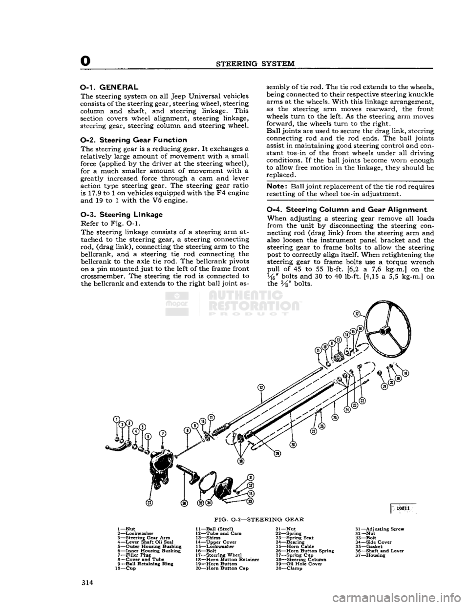
STEERING
SYSTEM
O-L
GENERAL
The
steering system on all Jeep Universal vehicles
consists of the steering gear, steering wheel, steering column and shaft, and steering linkage.
This
section covers wheel alignment, steering linkage,
steering gear, steering column and steering wheel.
0-2. Steering
Gear
Function
The
steering gear is a reducing gear. It exchanges a
relatively
large amount of movement with a small force (applied by the driver at the steering wheel), for a much smaller amount of movement with a
greatly increased force through a cam and lever
action type steering gear. The steering gear ratio is 17.9 to 1 on vehicles equipped with the F4
engine
and
19 to 1 with the V6 engine.
0-3. Steering
Linkage
Refer
to Fig. O-l.
The
steering linkage consists of a steering arm at
tached to the steering gear, a steering connecting
rod,
(drag
link),
connecting the steering arm to the
beilcrank,
and a steering tie rod connecting the
beilcrank
to the axle tie rod. The beilcrank pivots
on a pin mounted just to the left of the frame front crossmember. The steering tie rod is connected to
the beilcrank and
extends
to the right
ball
joint as sembly of tie rod. The tie rod
extends
to the wheels,
being connected to their respective steering knuckle
arms
at the wheels.
With
this linkage arrangement,
as the steering arm
moves
rearward,
the front
wheels
turn
to the left. As the steering arm
moves
forward,
the wheels
turn
to the right.
Ball
joints are used to secure the drag
link,
steering
connecting rod and tie rod ends. The
ball
joints
assist in maintaining
good
steering control and con
stant toe-in of the front wheels under all driving conditions. If the
ball
joints
become
worn enough
to allow free motion in the linkage, they should be,
replaced.
Note:
Ball
joint replacement of the tie rod requires
resetting of the wheel toe-in adjustment.
0-4.
Steering
Column
and Gear
Alignment
When
adjusting a steering gear remove all loads
from
the unit by disconnecting the steering con
necting rod (drag
link)
from the steering arm and
also
loosen
the instrument panel bracket and the
steering gear to frame
bolts
to allow the steering
post
to correctly align itself. When retightening the
steering gear to frame
bolts
use a torque wrench
pull
of 45 to 55 lb-ft. [6,2 a 7,6 kg-m.] on the
Vk*
bolts
and 30 to 40 lb-ft. [4,15 a 5,5 kg-m.] on the
Vs"
bolts. 10811
FIG.
0-2—STEERING
GEAR
1—Nut
2
—Lockwasher
3—
Steering
Gear
Arm 4—
Lever
Shaft Oil Seal
5—
Outer
Housing Bushing
6—
Inner
Housing Bushing 7—
Filler
Plug
8—
Cover
and Tube
9—
Ball
Retaining
Ring
10—Cup
11—
Ball
(Steel)
12—
Tube
and Cam
13—
Shims
14—
Upper
Cover
15—
Lockwasher
16—
Bolt
17—
Steering
Wheel 18—
Horn
Button Retainer
19—
Horn
Button
20—
Horn
Button Cap 21— Nut
22—
Spring
23—
Spring
Seat
24—
Bearing
25—
Horn
Cable
26—
Horn
Button Spring
27—
Spring
Cup
28—
Steering Column
29—
Oil
Hole
Cover
30—
Clamp
31—
Adjusting
Screw
32— Nut
33—
Bolt
34—
Side
Cover
35—
Gasket
36—
Shaft
and
Lever
37—
Housing
314
Page 321 of 376
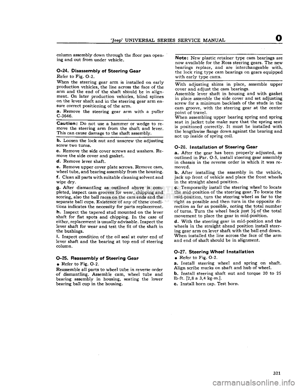
'Jeep'
UNIVERSAL
SERIES SERVICE
MANUAL
O
column assembly down through the floor pan open
ing and out from under vehicle.
0-24.
Disassembly
of
Steering
Gear
Refer
to Fig. 0-2.
When
the steering gear arm is installed on early
production vehicles, the line across the face of the
arm
and the end of the shaft should be in align ment. On later production vehicles, blind splines
on the lever shaft and in the steering gear arm en
sure
correct positioning of the arm.
a.
Remove the steering gear arm with a puller
C-3646.
Caution:
Do not use a hammer or
wedge
to re
move
the steering arm from the shaft and lever.
This
can cause damage to the shaft assembly.
b.
Loosen the lock nut and unscrew the adjusting
screw
two turns.
c.
Remove the side cover screws and washers. Re
move
the side cover and gasket.
d.
Remove lever shaft.
e.
Remove upper cover plate screws. Remove cam,
wheel tube, and bearing assembly from the housing.
f.
Clean
all parts with suitable cleaning solvent and wipe dry.
g.
After dismantling as outlined above is com
pleted, inspect cam
grooves
for wear, chipping and
scoring,
also the
ball
races on the cam ends and the
separate
ball
cups. Existence of any of
these
condi tions indicates the necessity for parts replacement.
h.
Inspect the tapered stud mounted on the lever
shaft for flat
spots
and chipping. In the case of
either, replacement is usually advisable. Inspect the
lever shaft for wear and
test
the fit of the shaft in
the bushings.
i.
Inspect condition of the oil seal at outer end of
lever shaft and the bearing at top end of steering
column.
0-25.
Reassembly
of
Steering
Gear
e Refer to Fig. 0-2.
Reassemble all parts to wheel tube in reverse order
of dismantling. Assemble cam, wheel tube and
bearing
assembly in housing, seating the lower
bearing
ball
cup in the housing.
Note:
New plastic retainer type cam bearings are
now available for the Ross steering gears. The new
bearings replace, and are interchangeable with,
the lock ring type cam bearings on gears equipped
with
early type cams.
With
adjusting shims in place, assemble upper
cover and adjust the cam bearings.
Assemble lever shaft in housing and with gasket
in
place assemble the side cover and set adjusting
screw
for a minimum backlash of the studs in the
cam
groove, with the steering gear at the center
point of travel.
When
assembling upper bearing spring and spring
seat in jacket tube make sure that the spring seat
is positioned correctly. It must be installed with
the lengthwise flange down against the bearing and
not up inside of spring coil.
0-26.
Installation
of
Steering
Gear
a.
After the gear has been properly adjusted, as
outlined in Par. 0-5, install steering gear assembly
in
chassis in the reverse order in which it was re
moved.
b.
After installing the assembly in the vehicle,
jack
up front of vehicle and place the front wheels
in
the straight ahead position.
c.
Temporarily install the steering wheel to locate
the mid-position of the steering gear. To locate the mid-position,
turn
the steering wheel as far to the
right
as possible and then
turn
in the
opposite
di
rection
as far as possible, noting the total number
of turns.
Turn
the wheel back just ^ of the total movement to place the gear in mid-position.
d.
With
the steering gear in mid-position and the
wheels in the straight ahead position install steer ing gear arm on lever shaft with the
ball
end down.
When
installed the line across the face of the arm
and
end of shaft should be in alignment.
0-27.
Steering
Wheel
Installation
•
Refer to Fig. 0-2.
a.
Install
steering wheel and spring on shaft.
Align
scribe marks on shaft and hub of wheel.
b.
Install
steering shaft nut and torque 20 to 25
lb-ft. [2,8 a 3,4 kg-m.].
c.
Install
horn cap. Test horn.
321
Page 327 of 376
'Jeep'
UNIVERSAL
SERIES SERVICE
MANUAL
P
lengthening of the brake master cylinder eye bolt.
This
is
done
so the primary cup
will
clear the by
pass port when the piston is in the off position,
otherwise the compensating action of the master
cylinder
for expansion and contraction of the fluid
in
the system, due to temperature changes,
will
be destroyed and cause the brakes to drag.
Note:
Some older 'Jeep' vehicles may
develop
side
movement
of the clutch and brake pedals resulting
from wear of the pedals, shafts, and bushings. One
way to
compensate
for this wear is to install a pedal
slack
adjuster kit,
Part
No.
921936.
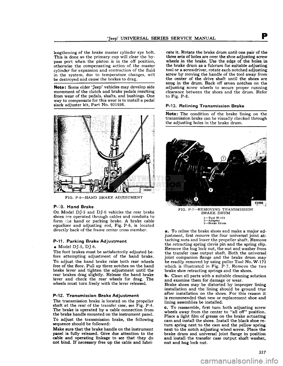
FIG.
P-6—HAND
BRAKE
ADJUSTMENT
P-10.
Hand Brake
On
Model DJ-5 and DJ-6 vehicles the rear brake
shoes
are operated through cables and conduits to
form the hand or parking brake. A brake cable
equalizer and adjusting rod, Fig. P-6, is located directly back of the frame center cross member.
P-11.
Parking Brake Adjustment
•
Model DJ-5, DJ-6.
The
foot
brakes must be satisfactorily adjusted be
fore attempting adjustment of the hand brake.
To
adjust the hand brake raise both rear
wheels
free of the floor.
Pull
up three
notches
on the hand
brake
lever and tighten the adjustment until the
rear
brakes drag slightly. Release the hand brake
lever and check the rear
wheels
for drag. The
wheels
must turn freely with the lever released.
P-12.
Transmission Brake Adjustment
The
transmission brake is located on the propeller
shaft at the rear of the transfer case, see Fig. P-4.
The
brake is operated by a cable connection from
the brake handle mounted on the instrument panel.
To
adjust the transmission brake, the following
sequence
should be followed:
Make
sure that the brake handle on the instrument
panel is fully released. Give due attention to the
cable and operating linkage to see that
they
do
not bind. If necessary free up the cable and
lubri
cate it. Rotate the brake drum until one pair of the
three
sets
of
holes
are over the
shoe
adjusting screw
wheels
in the brake. Use the
edge
of the
holes
in
the brake drum as a fulcrum for suitable adjusting
tool
or a screwdriver, rotate each notched adjusting
screw by moving the handle of the
tool
away from
the center of the drive shaft until the
shoes
are
snug in the drum.
Back
off seven
notches
on the
adjusting screw
wheels
to secure proper running clearance
between
the
shoes
and the drum. Refer
to Fig. P-8.
P-13.
Relining Transmission Brake
Note:
The condition of the brake lining on the
transmission brake can be visually checked through
the adjusting
holes
in the brake drum.
FIG.
P-7—REMOVING
TRANSMISSION
BRAKE
DRUM
1— Tool W-172
2—
Adapter
3—
Brake
Drum
a.
To reline the brake
shoes
and make a major ad
justment, first remove the four universal joint at taching nuts and lower the propeller shaft. Remove
the retracting spring clevis pin and the spring clip.
Remove the hug lock nut, the nut and washer from
the transfer case output shaft. Both the universal
joint companion
flange
and the brake drum may be readily removed by using puller Tool No. W-172
which
is illustrated in Fig. P-7. Remove the two
brake
shoe
retracting springs and the
shoes.
b. Clean all parts with a suitable cleaning solution
and
examine them for damage or wear.
Brake
shoes
may be distorted by improper lining
installation and the lining should be ground true
after installation on the
shoes.
For this reason it
is recommended that new or replacement
shoe
and
lining assemblies be installed.
c. To reassemble, first turn both adjusting screw
wheels
away from the center to "all off" position.
Place a light film of grease on the brake actuating
cam
and install the
shoes.
Install the black
shoe
re
turn
spring next to the cam and the yellow spring next to the notch adjusting wheel screw. Place the
brake
drum and universal joint
flange
in position
and
install the transfer case output shaft washer,
nut and hug lock nut. 327
Page 328 of 376
p
BRAKES
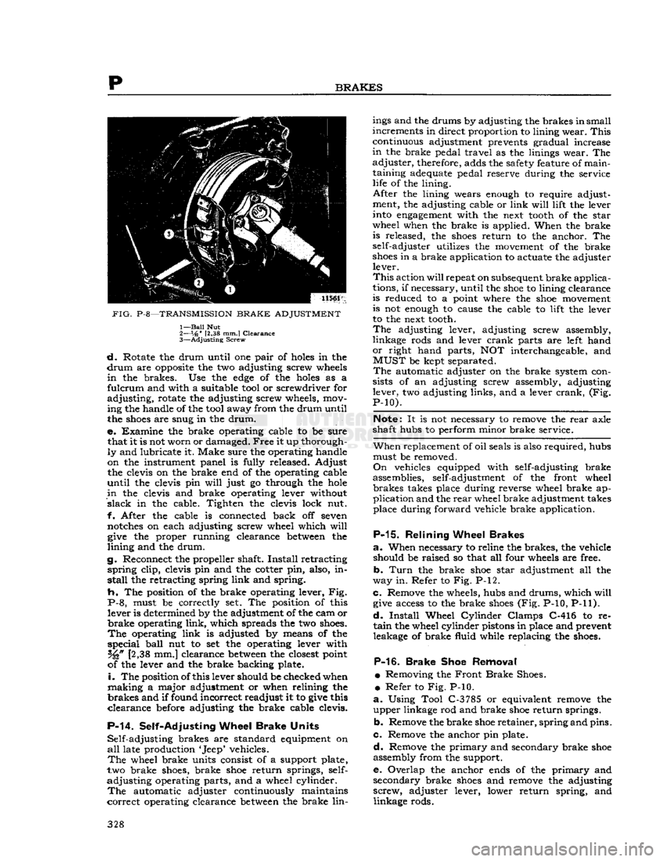
PIG.
P-8—TRANSMISSION
BRAKE
ADJUSTMENT
1—
Bail
Nut
2— s,6"
12,38 mm.I
Clearance
3—
Adjusting
Screw
d.
Rotate the
drum
until
one pair of holes in the
drum
are opposite the two adjusting screw wheels
in
the brakes. Use the
edge
of the holes as a
fulcrum
and
with
a suitable
tool
or screwdriver for
adjusting,
rotate the adjusting screw wheels,
mov
ing
the handle of the
tool
away
from
the
drum
until
the
shoes
are snug in the
drum.
e.
Examine the brake operating cable to be
sure
that
it is not
worn
or damaged. Free it up thorough
ly
and lubricate
it.
Make
sure
the operating handle
on
the instrument panel is
fully
released.
Adjust
the clevis on the brake end of the operating cable
until
the clevis pin
will
just go through the hole
in
the clevis and brake operating lever
without
slack
in the cable.
Tighten
the clevis
lock
nut.
f.
After
the cable is connected back off seven
notches on each adjusting screw wheel
which
will
give
the proper
running
clearance between the
lining
and the
drum.
g.
Reconnect the propeller shaft.
Install
retracting
spring
clip,
clevis pin and the cotter pin, also, in
stall
the retracting spring
link
and spring.
h. The
position
of the brake operating lever, Fig.
P-8, must be correctly set. The
position
of this
lever
is determined by the adjustment of the cam or
brake operating
link,
which
spreads
the two
shoes.
The
operating
link
is adjusted by
means
of the
special
ball
nut to set the operating lever
with
[2,38
mm.] clearance between the closest
point
of
the lever and the brake backing plate.
i.
The
position
of
this
lever should be checked when
making
a major adjustment or when
relining
the
brakes and
if
found
incorrect readjust it to give this
clearance before adjusting the brake cable
clevis.
P-14.
Self-Adjusting
Wheel
Brake
Units
Self-adjusting
brakes are standard equipment on
all
late production
'Jeep'
vehicles.
The
wheel brake units consist of a support plate,
two
brake
shoes,
brake
shoe
return springs, self-
adjusting
operating parts, and a wheel
cylinder.
The
automatic adjuster continuously maintains
correct
operating clearance between the brake
lin
ings
and the drums by adjusting the brakes
in
small
increments in direct
proportion
to
lining
wear. This
continuous
adjustment prevents gradual increase
in
the brake pedal
travel
as the
linings
wear. The
adjuster, therefore,
adds
the safety feature of
main
taining
adequate
pedal reserve
during
the service
life
of the
lining.
After
the
lining
wears enough to require adjustment, the adjusting cable or
link
will lift
the lever
into
engagement
with
the next
tooth
of the
star
wheel
when the brake is applied. When the brake
is
released, the
shoes
return to the anchor. The
self-adjuster
utilizes
the movement of the brake
shoes
in a brake application to
actuate
the adjuster
lever.
This
action
will
repeat
on
subsequent
brake applica
tions,
if
necessary,
until
the
shoe
to
lining
clearance
is
reduced to a
point
where the
shoe
movement
is
not enough to
cause
the cable to
lift
the lever
to
the next
tooth.
The
adjusting lever, adjusting screw assembly,
linkage
rods and lever crank parts are
left
hand
or
right
hand parts, NOT interchangeable, and
MUST
be kept
separated.
The
automatic adjuster on the brake system con
sists
of an adjusting screw assembly, adjusting
lever,
two adjusting
links,
and a lever crank, (Fig.
P-10).
Note:
It is not
necessary
to remove the rear axle
shaft hubs to
perform
minor
brake service.
When
replacement of
oil
seals
is also required, hubs must be removed.
On
vehicles equipped
with
self-adjusting brake
assemblies, self-adjustment of the
front
wheel brakes
takes
place
during
reverse wheel brake ap
plication
and the rear wheel brake adjustment
takes
place
during
forward
vehicle brake application.
P-15.
Relining
Wheel
Brakes
a.
When
necessary
to reline the brakes, the vehicle
should
be raised so that all
four
wheels are free.
b.
Turn
the brake
shoe
star
adjustment all the
way
in. Refer to Fig. P-12.
c.
Remove the wheels, hubs and drums,
which
will
give
access
to the brake
shoes
(Fig.
P-10, P-11).
d.
Install
Wheel
Cylinder
Clamps C-416 to re
tain
the wheel
cylinder
pistons in place and prevent leakage of brake
fluid
while
replacing the
shoes.
P-16.
Brake
Shoe
Removal
•
Removing the Front Brake
Shoes.
•
Refer to Fig. P-10.
a.
Using
Tool
C-3785
or equivalent remove the
upper linkage rod and brake
shoe
return springs.
b.
Remove the brake
shoe
retainer, spring and pins.
c. Remove the anchor pin plate.
d.
Remove the
primary
and secondary brake
shoe
assembly
from
the support.
e.
Overlap the anchor
ends
of the
primary
and
secondary brake
shoes
and remove the adjusting
screw, adjuster lever,
lower
return spring, and
linkage
rods. 328
Page 357 of 376
'Jeep'
UNIVERSAL SERIES SERVICE
MANUAL
u
MISCEIiLaNEOUS
Contents
SUBJECT
PAR.
Abbreviations
U-15
Extra
Equipment U-2
Front
Bumper Weight U-9
Governor
U-3
Governor
Adjustment U-4
Governor
Maintenance. U-6
U-1. GENERAL
Miscellaneous information included in this sectioi
includes coverage of extra equipment, special
tools,
torque specifications, and charts and tables.
U-2. EXTRA
EQUIPMENT
Much
of the utility of the
*
Jeep*
Universal
is due to
the extra equipment which has been designed to adapt it for farming and industry. The mainte
nance and use of
some
of this equipment is out
lined
in this section.
U-3.
Governor Assembly
The
Novi governor is supplied for models equipped
with
the F4 engine.
This
is a centrifugal type governor and is illustrated in Fig. U-2. Complete
installation
instructions are supplied with each
assembly. Adjustment and operating procedures
are
given below.
U-4.
Governor Adjustment
a.
Adjust the carburetor to obtain smooth
engine
idle at 600 rpm., then
stop
the engine.
b.
Check
throttle linkage to ensure maximum
throttle opening. Be certain that throttle and
governor linkage is free.
c.
Place the carburetor throttle in wide-open posi tion and
pull
the governor control handle out to
the last notch. Adjust the governor to bellcrank
rod
so that the linkage
will
hold the carburetor
throttle in wide-open position.
d.
Close the governor control and start the
engine
Again
pull
the control out to the last notch and
adjust
the length of the cable at adjusting yoke so
that the
engine
will
run at
2600
rpm. Close the
control
to recheck the linkage for free action and
to make sure the
engine
will
return to 600 rpm.
idle speed.
If
the
engine
runs faster than this speed,
loosen
the lock nut which locks the governor hand control
handle on the dash to the rod and back off the
handle until the carburetor idle speed adjusting
screw
bears on the stop. Tighten the lock nut.
In
the absence of electrical tachometer equipment,
engine
speed may be determined by the speedom
eter. Safely
jack
up the
rear
wheels and be sure the front wheel drive is not
engaged.
When driving
the
rear
wheels in high or direct transmission gear,
the
speedometer
will
read from 13j^ to 15 mph. [21.6 to 24.0 kph.] at an
engine
speed of from 900
to 1000 rpm.
SUBJECT
PAR.
Heater
U-10 Miscellaneous Data U-16
Pintle
Hook 1X7
Special
Tools. U-ll
Torque
Specifications U-13, 14, 15
Standard
and Recommended Tools
j.
.U-12
U-5.
Novi Governor Operation /
The
Novi governor is directly belted to the F4
engine
as no clutch is provided to disconnect the
drive.
To
operate the vehicle
WITHOUT
governor con
trol,
push the governor hand control all the way
IN
against the instrument panel.
To
operate the vehicle
WITH
governor control,
pull
the governor hand control handle out. The
hand
control has nine notched positions. Pulling the
control
out to the first notch
sets
the controlled
engine
speed at approximately 1000 rpm. and each successive notch increases the speed 200 rpm.
until
2600
rpm. is reached in the ninth notch. The
hand
control may be released by turning the han dle one-quarter
turn
in either direction.
When
the
engine
is being operated under governor
control
(hand control out) the controlled
engine
speed may be
exceeded
at any time by depressing
the
foot
accelerator in the conventional manner to
secure a greater carburetor throttle opening than
that determined by the governor hand control
setting.
U-6.
Governor Maintenance
The
belt tension may be adjusted by raising or
lowering the governor in the slotted
holes
in the mounting bracket. Keep the pulleys and belt free
of
dirt
and oil. Belt slippage
will
affect governor
operation and a tight belt may cause
rapid
wear
of the governor shaft and bearings. Adjust it to
allow Yi' [12,7 mm.] depression midway
between
the pulleys with thumb pressure.
There
is little wear of the internal parts for they
operate in oil. The governor housings are equipped
with
both
fill
and
drain
plugs and also with level
indicating
plugs.
Check
the oil level at each vehicle
lubrication
and change the oil each time the en
gine
oil is changed using the same grade oil used
in
the engine.
Caution:
Do not
fill
the governor housing above
the level plug. Overfilling
will
prevent governor
control
and possibly cause damage to governor in
ternal
parts. The capacity of
these
governors is two fluid ounces [59,15 cm3]. The filler plug is
also a vent which should be cleaned thoroughly at
each oil change to be sure that the vent operates.
U-7.
Pintle Hook
The
standard type pintle hook, Fig. U-1, affords a
safe, easy hitch for towing a
trailer
or other vehicle. 357
Page 358 of 376
u
MISCELLANEOUS
Designed primarily for use on the road, a safety
latch
locks the hook in the closed position and two
eye
bolts
are provided for attachment of safety chains which should be crossed when installed, to
prevent the hooks from jumping out of the
eyes.
Keep
the attaching
bolts
tight at all times. When
lubricating
the vehicle, place a few drops of oil on the hook and safety latch pivot pins.
FIG.
U-l—PINTLE HOOK
U-8.
Pintle Hook Installation
Six
holes
are provided in the frame
rear
cross mem
bers of 'Jeep* Universals for the installation of
pintle hooks and safety chain eye bolts. On most vehicles, the pintle hook is attached using the top
four
holes
and the eye
bolts
are attached using the
lower two holes. On 'Jeep* Universals equipped
with
tail
gates,
the position of the hook and the eye must be changed to provide proper clearance.
On
these
vehicles, use the lower four
holes
for attaching the pintle hook and the upper two
holes
for
attaching the safety chain eye bolts.
U-9.
Front
Bumper
Weight
The
best
performance of a four-wheel drive vehicle
is obtained when the load is equally distributed for
traction
on the front and
rear
wheels.
This
weight
distribution is disturbed when the vehicle is used
for drawbar work as the load on the
rear
wheels is increased and that on the front wheels decreased.
The
addition of a 265 pound front bumper weight
equalizes the load.
When
the load is equalized the front and
rear
axles
do approximately the same work which results in
prolonged life of
these
parts and considerably more
satisfactory performance.
The
bumper weight, Fig. U-3, is held in place by
four
bolts
and is provided with hand
holes
for lift
ing.
Do not add sand
bags
or other
weights
in the vehicle. When driving over rough
terrain,
with the
weight in place, the driver should exercise due care.
FIG.
U-2—NOVI
GOVERNOR
— F4 ENGINE
1—
Pivot
Bolt
2—
Cotter
Pin
3—
Governor
Beilcrank
4—
Adjusting
Block
5—
Governor
Control
6—
Screw
7—
Control
Bezel
8—
Handle
9—
Vertical
Rod
10—Washer
11
—Nut
12— Nut
and
Lockwasher
13—
Stud
14—
Washer
15—
Screw
16—
Support
Bracket
17—
Fan
Drive
Pulley
18—
Governor
Drive
Belt
19—
Governor
(Novi)
20—
Governor
Drive
Pulley
21—
Horizontal
Rod
22—
Beilcrank
Bracket
23—
Washer
358