wheel bolt torque JEEP CJ 1953 User Guide
[x] Cancel search | Manufacturer: JEEP, Model Year: 1953, Model line: CJ, Model: JEEP CJ 1953Pages: 376, PDF Size: 19.96 MB
Page 267 of 376
'Jeep'
UNIVERSAL SERIES SERVICE
MANUAL
ft
TRANSFER CASE
Contents
SUBJECT
PAR.
GENERAL
. . .K-1
TRANSFER CASE REMOVAL
K-2
TRANSFER CASE DISASSEMBLY
K-3
Front
Bearing Cap K-4
Rear
Bearing Cap K-5
TRANSFER CASE REASSEMBLY.
. .K-6
TRANSFER CASE INSTALLATION
K-7
TRANSFER CASE LINKAGE
ADJUSTMENT
K-8
SERVICE
DIAGNOSIS
K-9
SPECIFICATIONS
.K-10
K-1. GENERAL
All
4-wheel-drive models are equipped with a
transfer
case to connect the power to the front
axle.
It is essentially a
two-speed
transmission
located at the
rear
of the standard transmission
and
provides a low and direct gear.
The
transfer case gears are controlled by the
driver
through
one shift lever.
Early
'Jeep'
Universal
Models with the F4-134
Hurricane
engine
are equipped with two transfer case shift control levers.
a.
On vehicles equipped with one transfer case
shift
lever, the transfer case shift lever has four
positions: 2WD
High,
4WD
High,
Neutral, and
4WD
low. The forward position of the lever 2WD
High
allows the
rear
wheels only to drive. The
first
rear
position (4WD High)
engages
the 4- wheel drive and provides high range 4-wheel drive.
The
second
rear
position (Neutral)
disengages
all power to the wheels and is used for stationary
power take-off operations. The last
rear
position
(4WD
Low) provides low range 4-wheel drive.
b.
On vehicles equipped with two transfer case
shift
levers, the transfer case front axle drive lever (left hand lever)
gives
a choice of 2-wheel or 4-
wheel drive. In the forward (out) position the
vehicle is in 2-wheel drive. Move the lever to the
rear
(in) position for 4-wheel drive operation.
The
4-wheel-drive
auxiliary-range
shift lever (right
hand
lever) has three positions; low, neutral, and
high.
The forward position (low)
gives
low-range
4-wheel drive. The center position (neutral) dis
engages
all power to the wheels and is used for
stationary
power take-off operations. A built-in in
terlock
prevents shifting into low range, 2-wheel
drive.
This
feature protects the
rear
axle from over
load.
K-2.
Removal of
Transfer
Case
The
transfer case may be removed from the vehicle
without removing the transmission. Where both
transmission
and transfer case are to be removed
together,
refer to Section J. To remove only the
transfer
case from the vehicle, proceed as follows:
a.
Drain
transmission
and transfer case and replace
drain
plugs.
b.
Disconnect the brake cable.
c.
Disconnect front and
rear
propeller shafts at
the transfer case. See "Propeller Shafts and
Uni
versal
Joints."
d.
Disconnect
speedometer
cable at transfer case. e. Disconnect the transfer case shift levers. On
vehicles equipped with two shift levers
loosen
set screw and remove pivot pin. Use a screw
driver
to pry shift lever springs away from shift levers.
Lift
levers from transfer case. On models equipped
with
a single shift lever remove pivot pin cotter
key,
and the adjusting rod attaching nut to remove
shift
lever. See Fig. K-4.
f. Remove cover plate on
rear
face of transfer case.
Remove
cotter key, nut and washer from trans
mission
main shaft.
g. If possible, at this point remove the transfer case main drive gear from the transmission main
shaft.
If not possible, see
step
j below.
h.
Remove transfer case torque reaction support
bracket
bolt and nut.
i.
Remove transmission to transfer case bolts.
j.
Remove transfer case. If the transfer case main
drive
gear has not been removed in
step
g above,
proceed as follows:
Brace
the end of the trans
mission
main shaft so that it cannot
move
in the
transmission,
pull
the transfer case to the
rear
to 267
Page 278 of 376
M
FRONT
AXLE
1— Nut
2—
Lock
Washer
3—
Bearing
Lock
Washer
4—
Wheel
Bearing Cup 5—
Cone
and Rollers
6—
Oil
Seal 7— Spindle
8— Spindle Bushing
9—
Filler
Plug
10—
Right
Knuckle and Arm
11— Shims
12— Pivot Pin
13—
Lock
Washer
14—
Cap
Screw
15— Nut
16—
Washer
17—
Universal
Joint Yoke
18—
Oil
Seal
19—
Oil
Slinger
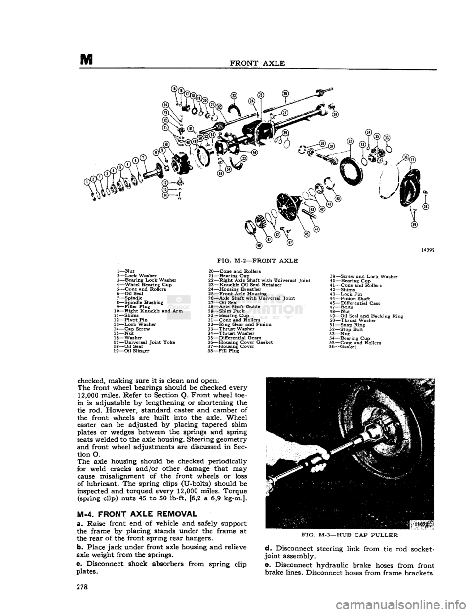
FIG.
M-2—FRONT
AXLE
20—
Cone
and Rollers
21—
Bearing
Cup
22—
Right
Axle Shaft with Universal Joint
23—
Knuckle
Oil Seal Retainer
24— Housing Breather 25—
Front
Axle Housing
26—
Axle
Shaft with Universal Joint
27—
Oil
Seal
28—
Axle
Shaft Guide
29—
Shim
Pack
30—
Bearing
Cup
31—
Cone
and Rollers
32—
Ring
Gear
and Pinion
33—
Thrust
Washer
34—
Thrust
Washer
35—
Differential
Gears
36— Housing Cover Gasket
37— Housing Cover
38—
Fill
Plug 39—
Screw
and
Lock
Washer
40—
Bearing
Cup
41—
Cone
and Rollers
42— Shims
43—
Lock
Pin
44—
Pinion
Shaft
45—
Differential
Case
47— Bolts
48— Nut
49—
Oil
Seal and Backing Ring
50—
Thrust
Washer
51— Snap Ring
52— Stop Bolt
53— Nut 54—
Bearing
Cup
55—
Cone
and Rollers
56—
Gasket
checked, making sure it is clean and open.
The
front wheel bearings should be checked every
12,000
miles. Refer to Section Q. Front wheel toe-
in
is adjustable by lengthening or shortening the
tie rod. However, standard caster and camber of
the front
wheels
are built
into
the axle. Wheel
caster can be adjusted by placing tapered shim
plates or
wedges
between
the springs and spring
seats
welded to the axle housing. Steering
geometry
and
front wheel adjustments are discussed in Sec tion O.
The
axle housing should be checked periodically
for weld cracks and/or other damage that may cause misalignment of the front
wheels
or
loss
of lubricant. The spring clips (U-bolts) should be
inspected and torqued every
12,000
miles. Torque (spring clip) nuts 45 to 50 lb-ft. [6,2 a 6,9 kg-m.].
M-4. FRONT
AXLE
REMOVAL
a.
Raise front end of vehicle
arid
safely support the frame by placing stands under the frame at
the rear of the front spring rear hangers.
b. Place
jack
under front axle housing and relieve
axle
weight
from the springs.
c. Disconnect shock absorbers from spring clip plates.
FIG.
M-3—HUB
CAP
PULLER
d.
Disconnect steering link from tie rod socket-
joint assembly.
e. Disconnect hydraulic brake
hoses
from front
brake
lines. Disconnect
hoses
from frame brackets. 278
Page 282 of 376
FRONT
AXLE
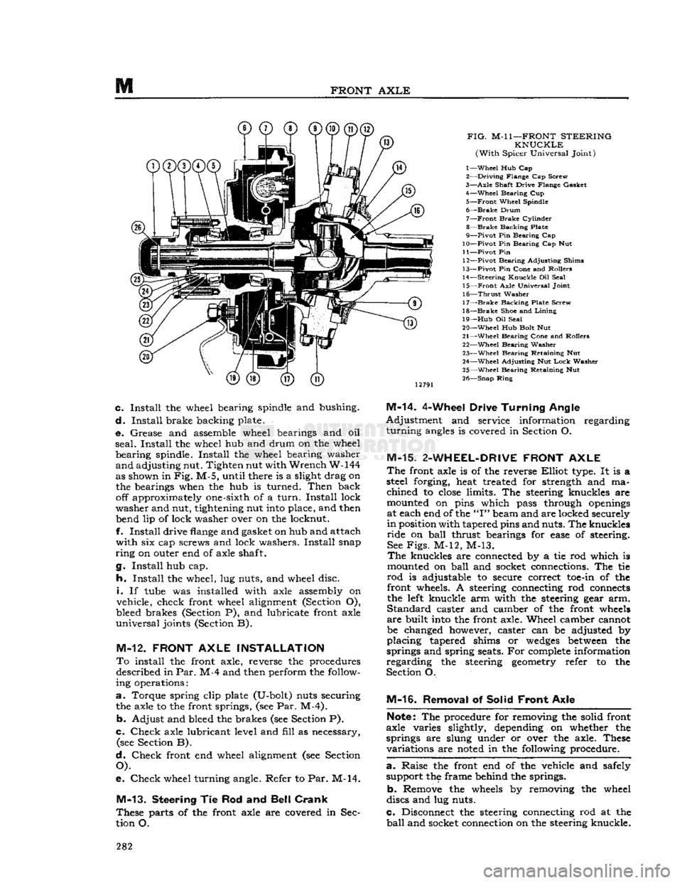
FIG.
M-l
1—FRONT
STEERING
KNUCKLE
(With
Spicer Universal Joint)
1—
Wheel
Hub Cap
2—
Driving
Flange Cap Screw
3—
Axle
Shaft Drive Flange Gasket 4—
Wheel
Bearing Cup
5—
Front
Wheel Spindle
6—
Brake
Drum
7—
Front
Brake
Cylinder
8—
Brake
Backing Plate
9—
Pivot
Pin Bearing Cap
10—
Pivot
Pin Bearing Cap Nut
11—
Pivot
Pin 12—
Pivot
Bearing Adjusting Shims
13—
Pivot
Pin Cone and Rollers
14—
Steering
Knuckle
Oil Seal 15—
Front
Axle Universal Joint
16—
Thrust
Washer
17—
Brake
Backing Plate Screw
18—
Brake
Shoe and
Lining
19—
Hub
Oil Seal
20—
Wheel
Hub Bolt Nut
21—
Wheel
Bearing Cone and Rollers 22—
Wheel
Bearing Washer
23—
Wheel
Bearing Retaining Nut
24—
Wheel
Adjusting Nut
Lock
Washer
25—
Wheel
Bearing Retaining Nut
26—
Snap
Ring
c.
Install
the wheel bearing spindle and bushing.
d.
Install
brake backing plate.
e.
Grease and assemble wheel bearings and oil
seal.
Install
the wheel hub and drum on the wheel
bearing
spindle.
Install
the wheel bearing washer
and
adjusting nut. Tighten nut with
Wrench
W-144
as shown in
Fig.
M-5, until there is a slight drag on the bearings when the hub is turned.
Then
back off approximately one-sixth of a
turn.
Install
lock
washer
and nut, tightening nut
into
place, and then bend lip of lock washer over on the locknut.
f.
Install
drive
flange
and gasket on hub and attach
with
six cap screws and lock washers.
Install
snap
ring
on outer end of axle shaft.
g.
Install
hub cap.
h.
Install
the wheel, lug nuts, and wheel disc.
i.
If
tube
was installed with axle assembly on
vehicle, check front wheel alignment (Section O),
bleed brakes (Section P), and lubricate front axle
universal
joints (Section B).
M-12.
FRONT
AXLE
INSTALLATION
To
install the front axle, reverse the procedures described in
Par.
M-4 and then perform the follow
ing operations:
a.
Torque spring clip plate (U-bolt) nuts securing the axle to the front springs, (see Par. M-4).
b.
Adjust and bleed the brakes (see Section P).
c.
Check
axle lubricant level and
fill
as necessary, (see Section B).
d.
Check
front end wheel alignment (see Section
O).
e.
Check
wheel turning angle. Refer to Par. M-14.
M-13.
Steering
Tie Rod and
Bell Crank
These
parts of the front axle are covered in Sec
tion O.
M-14.
4-Wheel Drive
Turning
Angle
Adjustment
and service information regarding
turning
angles
is covered in Section O.
M-15.
2-WHEEL-DRIVE
FRONT
AXLE
The
front axle is of the reverse
Elliot
type. It is a
steel forging, heat treated for strength and ma
chined
to
close
limits. The steering knuckles are
mounted on pins which pass through
openings
at each end of the
"I"
beam and are locked securely
in
position with tapered pins and nuts. The knuckles
ride
on
ball
thrust bearings for
ease
of steering. See
Figs.
M-12, M-13.
The
knuckles are connected by a tie rod which is
mounted on
ball
and socket connections. The tie
rod
is adjustable to secure correct
toe-in
of the front wheels. A steering connecting rod
connects
the
left
knuckle arm with the steering gear arm.
Standard
caster and camber of the front
wheels
are
built
into
the front axle. Wheel camber cannot
be changed however, caster can be adjusted by
placing
tapered shims or
wedges
between
the
springs and spring seats. For
complete
information
regarding
the steering
geometry
refer to the
Section O.
M-16.
Removal of Solid
Front
Axle
Note:
The procedure for removing the solid front
axle varies slightly, depending on whether the
springs are slung under or over the axle. These
variations
are
noted
in the following procedure.
a. -
Raise the front end of the vehicle and safely support the frame behind the springs.
b.
Remove the
wheels
by removing the wheel
discs and lug nuts.
c.
Disconnect the steering connecting rod at the
ball
and socket connection on the steering knuckle. 282
Page 292 of 376
N
REAR
AXLE
FIG.
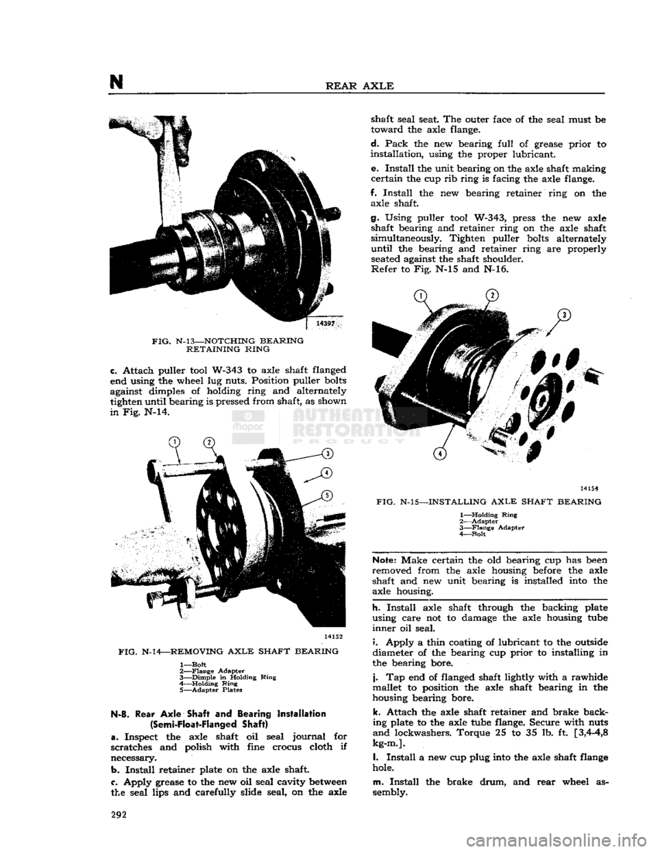
N-l3—NOTCHING
BEARING
RETAINING
RING
c.
Attach puller
tool
W-343 to axle shaft flanged
end using the wheel lug nuts. Position puller
bolts
against dimples of holding ring and alternately tighten until bearing is pressed from shaft, as shown
in
Fig. N-14. 14152
FIG.
N-14—REMOVING
AXLE
SHAFT
BEARING
1—
Bolt
2—
Flange
Adapter
3—
Dimple
in Holding
Ring
4 Holding
Ring
5—
Adapter
Plates N-8.
Rear
Axle
Shaft and Bearing Installation
(Semi-Float-Flanged
Shaft)
a.
Inspect the axle shaft oil seal
journal
for
scratches and polish with fine crocus cloth if
necessary.
b.
Install
retainer plate on the axle shaft
c.
Apply grease to the new oil seal cavity
between
the seal lips and carefully slide seal, on the axle shaft seal seat. The outer face of the seal must be
toward
the axle flange.
d.
Pack
the new bearing
full
of grease
prior
to
installation,
using the proper lubricant.
e.
Install
the unit bearing on the axle shaft making
certain
the cup rib ring is facing the axle flange.
f.
Install
the new bearing retainer ring on the axle shaft.
g. Using puller
tool
W-343, press the new axle shaft bearing and retainer ring on the axle shaft
simultaneously. Tighten puller
bolts
alternately
until
the bearing and retainer ring are properly
seated
against the shaft shoulder.
Refer
to Fig. N-15 and N-16. 14154
FIG.
N-15—INSTALLING
AXLE
SHAFT
BEARING
1—
Holding
Ring
2—
Adapter
3—
Flange
Adapter
4—
Bolt
Note:
Make certain the old bearing cup has
been
removed from the axle housing
before
the axle
shaft and new unit bearing is installed
into
the
axle housing.
h.
Install
axle shaft through the backing plate
using care not to damage the axle housing
tube
inner
oil seal.
i.
Apply a thin coating of lubricant to the
outside
diameter of the bearing cup
prior
to installing in
the bearing bore.
j.
Tap end of flanged shaft lightly with a rawhide
mallet to position the axle shaft bearing in the
housing bearing bore.
k.
Attach the axle shaft retainer and brake back
ing plate to the axle
tube
flange. Secure with nuts
and
lockwashers. Torque 25 to 35 lb. ft
[3,4-4,8
kg-m.].
I.
Install
a new cup plug
into
the axle shaft
flange
hole.
m.
Install
the brake
drum,
and
rear
wheel as
sembly. 292
Page 302 of 376
N
REAR
AXLE a.
Place the transmission in neutral.
b.
Raise one wheel off the floor and place a block
in
front and at the
rear
of the
opposite
wheel.
c.
Apply a torque wrench to the axle shaft nut of
the elevated wheel.
d.
Turn
wheel with torque wrench. Disregard
breakaway
torque and observe torque required to
continuously
turn
wheel smoothly. Torque should
read
40 lb-ft [5,53 kg-m.] or more.
N-23. Powr-Lok
Differential Disassembly
/
and Reassembly
Refer
to
Figs.
N-38 and N-39.
The
procedure for overhauling disc type
Powr-Lok
differentials is as follows:
a.
Remove axle shafts following procedure de
scribed
in Par. N-2.
b.
Remove housing cover and gasket.
c.
Remove the
Powr-Lok
differential from the axle.
Do not remove the ring gear or bearing
cone
and
rollers
unless replacement is to be made.
Mark
the hearing cups so they may later be reassembled
with
the same bearing cones.
Mark
the differential
case halves for correct alignment at reassembly.
Each
pinion mate cross shaft should also be marked
so that each pin cam surface
will
match with the
same
V-ramp
in the case when reassembled.
d.
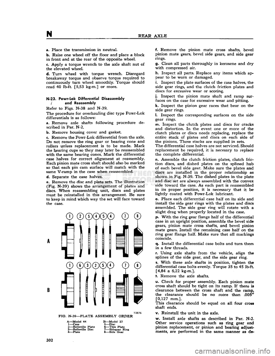
Separate the case halves. e. Remove the disc and plate
sets.
The illustration
(Fig.
N-39) shows the arrangement of plates and
discs.
When reassembling unit, discs and plates must be reinstalled in this arrangement. Be sure
to keep in mind which way the set
will
face toward the case.
^®(j)(j)CD©
® /'Ml
I
11
11 v
FIG.
N-39—PLATE
ASSEMBLY
ORPER
A—Model
44
B—Model
27 1—
Case
5—Disc
2—
Belleville
Plate
6—Thin
Plate
3—
Belleville
Disc
7—Sidegear
Ring
4—Plate
8—Side
Gear
f. Remove the pinion mate cross shafts, bevel
pinion mate gears, bevel side gears, and side gear
rings.
g.
Clean
all parts thoroughly in kerosene and dry
with
compressed air.
h.
Inspect all parts. Replace any items which ap
pear
to be worn or damaged.
i.
Inspect the plate surfaces of the case halves, the
side gear rings, and the clutch friction plates and
discs for excessive wear or scoring.
j.
Inspect the pinion mate shaft and ramp
sur
faces on the case for excessive wear and pitting,
k.
Inspect the pinion gear races that bear on the
side gear rings.
I.
Inspect the corresponding surfaces on the side
gear rings.
m.
Inspect the clutch plates and discs for cracks
and
distortion. In the
event
one or more of the
clutch
plates or discs
needs
replacing, replace the
entire stack of plates and discs on each side of
the pinions. These stacks are supplied in
sets.
The
differential case halves are not serviced. Should replacement be required, it is necesary to replace
the complete differential.
n.
Assemble the clutch friction plates, clutch
fric
tion discs, and dished plates on the splined hub of each bevel side gear. Make sure the plates and
discs are installed in the proper relationship as shown in Fig. N-39. The dished plates in the plate
and
disc set are always assembled with the convex
side toward the case. As each part is reassembled
in
its proper position, it is necessary that it be lightly coated with
Powr-Lok
lubricant,
o.
Place each differential case
half
on its side and
install
the side gear rings with the plates and discs
assembled. The side gear ring
will
rotate with a slight drag when properly located in the case,
p.
With
the ring gear flange
half
of the differential
case in an upright position, assemble the bevel side gears, pinion mate cross shafts, and bevel pinion
mate gears.
Install
the remaining case
half
on the
ring
gear flange half. Make sure that all markings
coincide.
q.
Install
the differential case
bolts
and
turn
them
in
a few threads.
r.
Using axle shafts from the vehicle, align the
splines of the side gear, and the side gear
ring,
s.
With
these
axle shafts in position, tighten the
differential
case
bolts
evenly. Torque 35 to 45 lb-ft. [4,84 a 6,22 kg-m.].
t. Remove the axle shafts.
u.
Check
for proper assembly.
Each
pinion mate
cross shaft should be tight on its
ramp.
If there is
clearance
between
the cross shaft and the
ramp,
the clearance should be no more than .005" [0,127 mm.].
This
clearance should be equal on all four cross
shaft ends.
v. Reinstall the unit in the axle.
w.
Install
axle shafts as described in Par. N-2.
Other
service operations such as ring gear and
pinion replacement, or pinion and bearing adjust ments, are performed in the same manner as de- 302
Page 314 of 376
STEERING
SYSTEM
O-L
GENERAL
The
steering system on all Jeep Universal vehicles
consists of the steering gear, steering wheel, steering column and shaft, and steering linkage.
This
section covers wheel alignment, steering linkage,
steering gear, steering column and steering wheel.
0-2. Steering
Gear
Function
The
steering gear is a reducing gear. It exchanges a
relatively
large amount of movement with a small force (applied by the driver at the steering wheel), for a much smaller amount of movement with a
greatly increased force through a cam and lever
action type steering gear. The steering gear ratio is 17.9 to 1 on vehicles equipped with the F4
engine
and
19 to 1 with the V6 engine.
0-3. Steering
Linkage
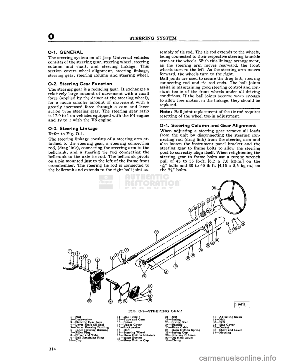
Refer
to Fig. O-l.
The
steering linkage consists of a steering arm at
tached to the steering gear, a steering connecting
rod,
(drag
link),
connecting the steering arm to the
beilcrank,
and a steering tie rod connecting the
beilcrank
to the axle tie rod. The beilcrank pivots
on a pin mounted just to the left of the frame front crossmember. The steering tie rod is connected to
the beilcrank and
extends
to the right
ball
joint as sembly of tie rod. The tie rod
extends
to the wheels,
being connected to their respective steering knuckle
arms
at the wheels.
With
this linkage arrangement,
as the steering arm
moves
rearward,
the front
wheels
turn
to the left. As the steering arm
moves
forward,
the wheels
turn
to the right.
Ball
joints are used to secure the drag
link,
steering
connecting rod and tie rod ends. The
ball
joints
assist in maintaining
good
steering control and con
stant toe-in of the front wheels under all driving conditions. If the
ball
joints
become
worn enough
to allow free motion in the linkage, they should be,
replaced.
Note:
Ball
joint replacement of the tie rod requires
resetting of the wheel toe-in adjustment.
0-4.
Steering
Column
and Gear
Alignment
When
adjusting a steering gear remove all loads
from
the unit by disconnecting the steering con
necting rod (drag
link)
from the steering arm and
also
loosen
the instrument panel bracket and the
steering gear to frame
bolts
to allow the steering
post
to correctly align itself. When retightening the
steering gear to frame
bolts
use a torque wrench
pull
of 45 to 55 lb-ft. [6,2 a 7,6 kg-m.] on the
Vk*
bolts
and 30 to 40 lb-ft. [4,15 a 5,5 kg-m.] on the
Vs"
bolts. 10811
FIG.
0-2—STEERING
GEAR
1—Nut
2
—Lockwasher
3—
Steering
Gear
Arm 4—
Lever
Shaft Oil Seal
5—
Outer
Housing Bushing
6—
Inner
Housing Bushing 7—
Filler
Plug
8—
Cover
and Tube
9—
Ball
Retaining
Ring
10—Cup
11—
Ball
(Steel)
12—
Tube
and Cam
13—
Shims
14—
Upper
Cover
15—
Lockwasher
16—
Bolt
17—
Steering
Wheel 18—
Horn
Button Retainer
19—
Horn
Button
20—
Horn
Button Cap 21— Nut
22—
Spring
23—
Spring
Seat
24—
Bearing
25—
Horn
Cable
26—
Horn
Button Spring
27—
Spring
Cup
28—
Steering Column
29—
Oil
Hole
Cover
30—
Clamp
31—
Adjusting
Screw
32— Nut
33—
Bolt
34—
Side
Cover
35—
Gasket
36—
Shaft
and
Lever
37—
Housing
314
Page 315 of 376
'Jeep'
UNIVERSAL
SERIES SERVICE
MANUAL
O Note:
If the steering-gear-to-frame
bolts
are not
properly
torqued, they
will
eventually
loosen
dur
ing operation of the vehicle. Loose
bolts
will
result
in
elongated
bolt
holes
making maintenance of bolt torque difficult, and may allow position of the
steering columns to be misaligned. Therefore,
proper
torquing is extremely important.
Do not tighten the steering gear to dampen out
steering trouble. Adjust the steering gear only to
remove lost motion or play within the unit.
0-5. Steering
Gear
Adjustment
The
cam and lever steering gear is illustrated in
Fig.
0-2. It consists of a
spiral
cam, and a cross shaft and lever assembly with two lever studs.
When
the steering wheel is turned, the cam
moves
the studs, causing rotary movement of the cross
shaft, which in
turn
causes angular movement of
the*steering arm.
Two
adjustments of the steering gear are necessary:
up and down play of the steering shaft, and adjustment of the lever studs (tapered pins) in the
cam
groove.
Adjustment
of the
ball
thrust bearings to eliminate up and down play of the steering shaft is ac
complished by removing shims which are installed
between
the steering gear housing and the upper
cover. Before making this adjustment
loosen
the
housing side cover adjusting screw to free the pins
in
the cam groove. Loosen the housing cover to
cut and remove a shim or more as required.
Install
the screws and tighten. Adjustment should be
made to have a slight drag but allow the steering
wheel to
turn
freely with thumb and forefinger
lightly gripping the rim.
Shims
installed for adjustment are .002*, .003", and .010"
[.0508,
.0762
and .254 mm.] in thickness.
Adjustment
of the tapered pins in the cam
groove
is accomplished by adjusting screw. Unlock the
adjusting
screw and
turn
it in until a very slight
drag
is felt through the mid-position when turning
the steering wheel slowly from one extreme position
to the other.
Backlash
of the pins in the
groove
shows up as
end play of lever shaft, also as backlash of steer ing arm.
The
cam
groove
is purposely cut shallow in the
straight
ahead driving position for each pin.
This
feature permits a
close
adjustment for normal
straight
ahead driving and provides precision steer ing and permits take up of backlash at this point
after the wear occurs without causing a bind else
where.
Always
adjust within the high range through
the mid-position of pin travel. Do not adjust off
"straight
ahead" position.
Backlash
in turned posi
tions is not objectionable.
0-6.
Front
Wheel Alignment Adjustments
To
ensure correct alignment, a definite procedure
for inspection of the steering system is recom mended. It is
suggested
that the following sequence
be used:
a.
Equalize
tire pressures and level vehicle.
b.
Check
steering gear to steering column align
ment.
c.
Inspect steering knuckle pivots, spindle, and
wheel bearing
looseness.
d.
Check
wheel runout.
e.
Test wheel balance and bearing adjustment.
f.
Check
for spring sag.
g.
Inspect brakes and shock absorbers.
h.
Check
steering gear assembly adjustment and
steering connecting rod.
i.
Check
caster,
j.
Check
toe-in.
k.
Check
toe-out
on turns.
I.
Check
camber.
m.
Check
tracking of front and
rear
wheels,
n.
Check
frame alignment.
The
factors of alignment, caster, camber, and toe-
in,
are all interrelated and if one adjustment is
made, another adjustment may be affected.
There
fore, after an alignment job is completed, make a
complete recheck of all the adjustments to be sure
the
settings
are within the limit. Be sure all front
suspension and steering system nuts and
bolts
are
all
properly torqued before taking wheel alignment readings.
Proper
alignment of front wheels must be main
tained in order to ensure
ease
of steering and satisfactory tire life.
The
most important factors of front wheel alignment are wheel camber, axle caster and wheel
toe-in.
Wheel
toe-in is the distance the wheels are closer
together
at the front than at the
rear.
Wheel
camber is the amount the wheels incline out
ward
at the top from a vertical position.
Front
axle caster is the amount in
degrees
that the
steering pivot pins are tilted towards the front or
rear
of the vehicle. Positive caster is inclination of
the top of the pivot pin towards the
rear
of the ve
hicle.
Zero caster is the vertical position of the
pivot pin. Negative or reverse caster is the in
clination
of the top of the pin towards the front
of the vehicle.
These
points should be checked at regular inter
vals,
particularly when the front axle has been
subjected to a heavy impact. When checking wheel alignment, it is important that wheel bearings and
knuckle
bearings be in proper adjustment. Loose bearings
will
affect instrument readings when
checking
the camber, pivot pin inclination and
toe-in.
To
accurately check camber and caster, use a wheel
aligning fixture.
Camber
and caster of the front
wheels are both preset.
Camber
cannot be altered
but caster can be adjusted by installing caster shims
between
the axle pad and the springs. Wheel toe-in
may
be adjusted. To measure wheel toe-in, use a
wheel aligning fixture or follow the procedure given
in Par.
0-8.
0-7.
Front Wheel Toe-in
Toe-in
as illustrated in
Fig.
0-3, is necessary to
off
set the
effect
of camber as shown in Fig. Q-4. 315
Page 320 of 376
STEERING
SYSTEM
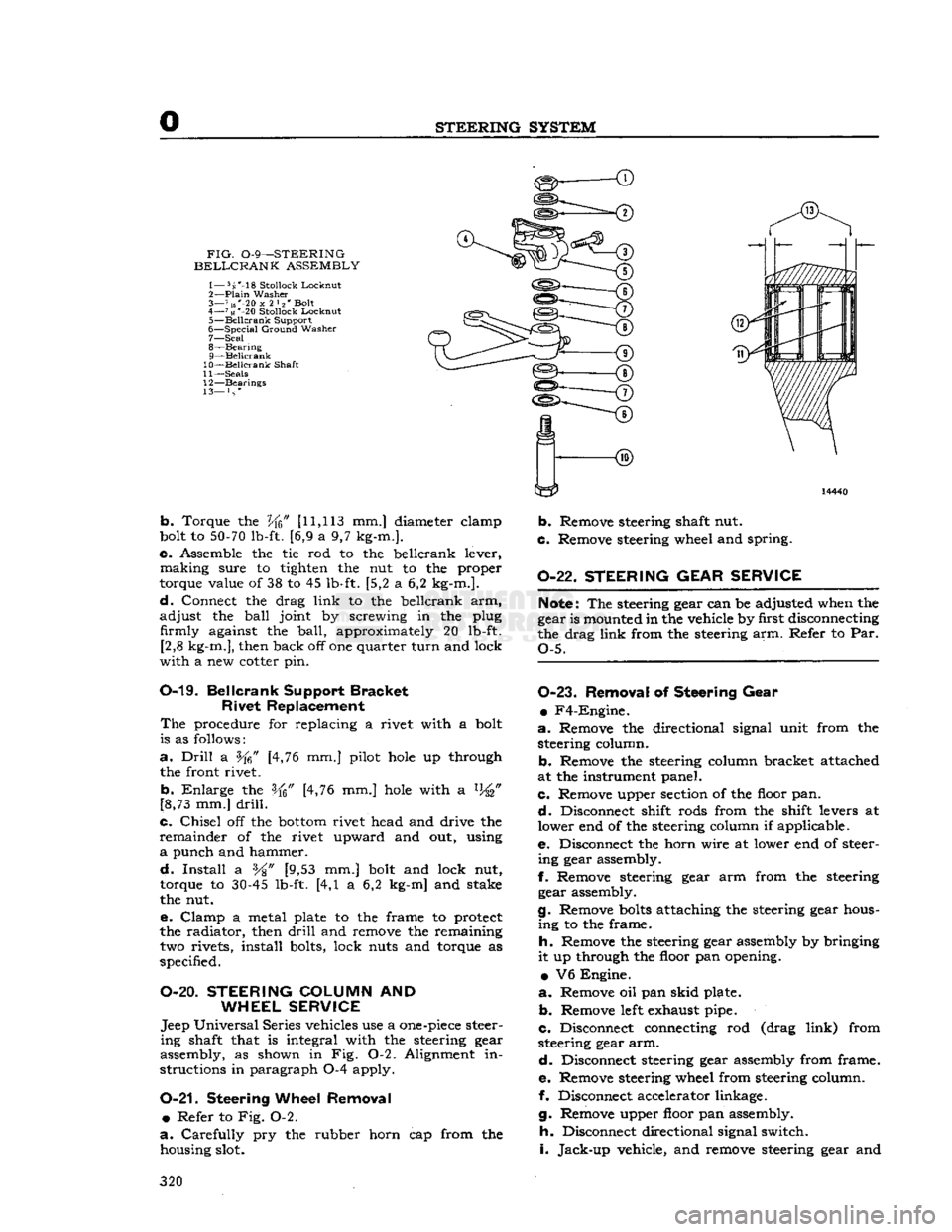
FIG.
0-9—STEERING
BELLCRANK
ASSEMBLY
1— 5s'-18
Stollock
Lockout
2—
Plain
Washer
3— 7 us"-20
x
2 l2' Bolt
4—
71«
*-20
Stollock
Locknut
5—
Beilcrank
Support
6—
Special
Ground
Washer
7— Seal
8—
Bearing
9— Beilcrank
10— Beilcrank
Shaft
11—
Seals
12—
Bearings
13— } s *
b.
Torque the
Vfc"
[11,113
mm.] diameter elamp
bolt to
50-70
lb-ft. [6,9 a 9,7 kg-m.].
c.
Assemble the tie rod to the beilcrank lever,
making
sure to tighten the nut to the proper
torque value of 38 to 45 lb-ft. [5,2 a 6,2 kg-m.].
d.
Connect the drag
link
to the beilcrank arm,
adjust
the
ball
joint by screwing in the plug firmly against the
ball,
approximately 20 lb-ft. [2,8 kg-m.], then back off one quarter
turn
and lock
with
a new cotter pin.
0-19.
Beilcrank
Support
Bracket
Rivet
Replacement
The
procedure for replacing a rivet with a bolt
is as follows:
a.
Drill
a [4,76 mm.] pilot
hole
up through
the front rivet.
b.
Enlarge
the [4,76 mm.]
hole
with a %"
[8,73 mm.]
drill.
c.
Chisel
off the
bottom
rivet head and drive the
remainder
of the rivet upward and out, using
a
punch and hammer.
d.
Install
a %" [9,53 mm.] bolt and lock nut,
torque to
30-45
lb-ft. [4,1 a 6,2 kg-m] and stake
the nut.
e.
Clamp
a metal plate to the frame to protect
the radiator, then
drill
and remove the remaining two rivets, install bolts, lock nuts and torque as
specified.
O-20.
STEERING
COLUMN
AND
WHEEL SERVICE
Jeep
Universal
Series vehicles use a
one-piece
steer
ing
shaft that is integral with the steering gear
assembly, as shown in Fig. 0-2. Alignment in
structions in paragraph 0-4 apply.
0-21.
Steering
Wheel Removal •
Refer to Fig. 0-2.
a.
Carefully
pry the rubber horn cap from the housing slot.
b.
Remove steering shaft nut.
c.
Remove steering wheel and spring.
0-22.
STEERING GEAR SERVICE
Note:
The steering gear can be adjusted when the
gear is mounted in the vehicle by first disconnecting
the drag
link
from the steering arm. Refer to Par.
Q-5.
0-23.
Removal
of
Steering Gear
•
F4-Engine.
a.
Remove the directional signal unit from the steering column.
b.
Remove the steering column bracket attached
at the instrument panel.
c.
Remove upper section of the floor pan.
d.
Disconnect shift rods from the shift levers at
lower end of the steering column if applicable.
e.
Disconnect the horn wire at lower end of steer
ing
gear assembly.
f.
Remove steering gear arm from the steering gear assembly.
g.
Remove
bolts
attaching the steering gear hous
ing
to the frame.
h.
Remove the steering gear assembly by bringing
it
up through the floor pan opening.
•
V6 Engine.
a.
Remove oil pan
skid
plate.
b.
Remove
left
exhaust pipe.
c.
Disconnect connecting rod (drag
link)
from
steering gear arm.
d.
Disconnect steering gear assembly from frame.
e.
Remove steering wheel from steering column.
f. Disconnect accelerator linkage.
g.
Remove upper floor pan assembly.
h.
Disconnect directional signal switch.
i.
Jack-up
vehicle, and remove steering gear and
320
Page 338 of 376
Q
WHEELS
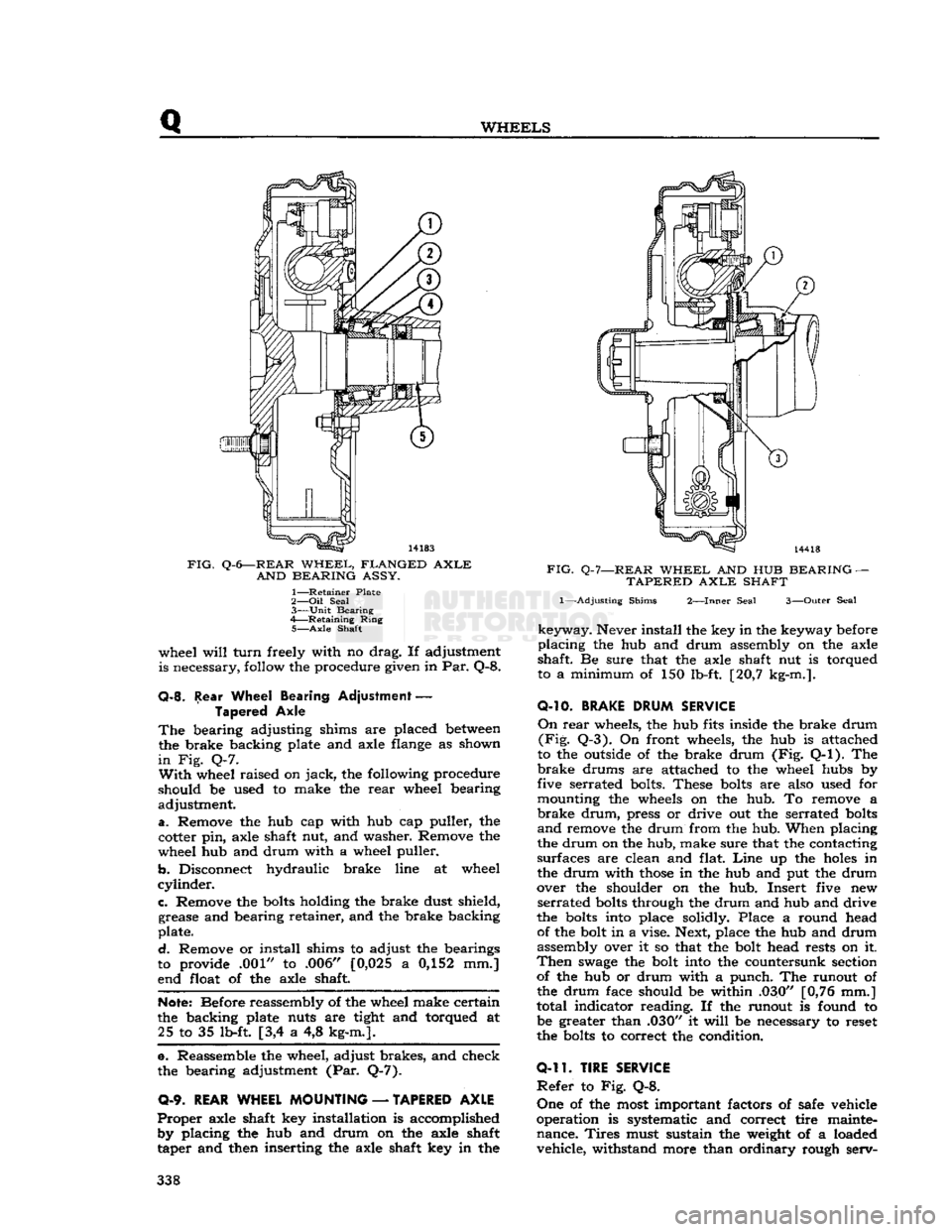
FIG.
Q-6—REAR
WHEEL,
FLANGED
AXLE
AND
BEARING
ASSY.
1—
Retainer
Plate
2— Oil
Seal
3—
Unit
Bearing
4—
Retaining
Ring
5—
Axle
Shaft
wheel
will
turn
freely with no drag. If adjustment
is necessary, follow the procedure given in Par. Q-8.
Q-8.
Rear Wheel Bearing Adjustment
—
Tapered Axle
The
bearing adjusting shims are placed
between
the brake backing plate and axle flange as shown
in
Fig. Q-7.
With
wheel raised on
jack,
the following procedure
should be used to make the
rear
wheel bearing
adjustment.
a.
Remove the hub cap with hub cap puller, the
cotter pin, axle shaft nut, and washer. Remove the
wheel hub and drum with a wheel puller.
b.
Disconnect hydraulic brake line at wheel
cylinder.
c.
Remove the
bolts
holding the brake dust shield, grease and bearing retainer, and the brake backing
plate.
d.
Remove or install shims to adjust the bearings
to provide .001" to .006" [0,025 a 0,152 mm.]
end float of the axle shaft.
Note:
Before reassembly of the wheel make certain
the backing plate nuts are tight and torqued at 25 to 35 lb-ft [3,4 a 4,8 kg-m.].
e. Reassemble the wheel, adjust brakes, and check
the bearing adjustment (Par. Q-7).
0-9.
REAR WHEEL MOUNTING
—
TAPERED AXLE
Proper
axle shaft key installation is accomplished by placing the hub and drum on the axle shaft
taper and then inserting the axle shaft key in the
FIG.
Q-7—REAR
WHEEL
AND HUB
BEARING
—
TAPERED
AXLE
SHAFT
1—-Adjusting
Shims
2—Inner
Seal
3—Outer
Seal
keyway.
Never install the key in the keyway before
placing
the hub and drum assembly on the axle
shaft. Be sure that the axle shaft nut is torqued
to a minimum of 150 lb-ft. [20,7 kg-m.].
O-10.
BRAKE
DRUM
SERVICE
On
rear
wheels, the hub fits inside the brake drum
(Fig.
Q-3). On front wheels, the hub is attached
to the outside of the brake drum (Fig. Q-l). The
brake
drums are attached to the wheel hubs by
five serrated bolts. These
bolts
are also used for
mounting the wheels on the hub. To remove a
brake
drum,
press or drive out the serrated
bolts
and
remove the drum from the hub. When placing
the drum on the hub, make sure that the contacting
surfaces are clean and flat.
Line
up the
holes
in
the drum with
those
in the hub and put the drum
over the shoulder on the hub. Insert five new
serrated
bolts
through the drum and hub and drive
the
bolts
into place solidly. Place a round head of the bolt in a vise. Next, place the hub and drum
assembly over it so that the bolt head rests on it.
Then
swage
the bolt into the countersunk section of the hub or drum with a punch. The runout of
the drum face should be within .030" [0,76 mm.]
total indicator reading. If the runout is found to be greater than .030" it
will
be necessary to reset
the
bolts
to correct the condition.
0-11.
TIRE SERVICE
Refer
to Fig. Q-8.
One
of the most important factors of safe vehicle
operation is systematic and correct tire mainte nance.
Tires
must sustain the weight of a loaded vehicle, withstand more than ordinary rough serv- 338
Page 346 of 376
SPRINGS
AND
SHOCK
ABSORBERS
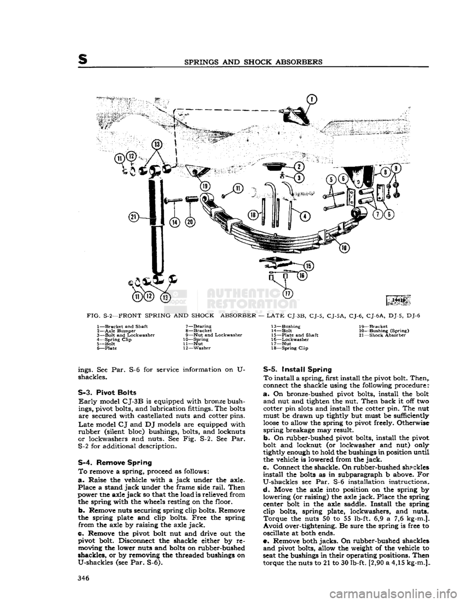
FIG.
S-2—FRONT
SPRING
AND
SHOCK
ABSORBER
—
LATE
CJ-3B,
CJ-5,
CJ-5A,
CJ-6,
CJ-6
A,
DJ-5, DJ-6 1—
Bracket
and Shaft
2—
Axle
Bumper
3—
Bolt
and
Lockwasher
4—
Spring
Clip
5—
Bolt
6—
Plate
7—
Bearing
8—
Bracket
9—
Nut
and
Lockwasher
10—
Spring
11—
Nut
12—
Washer
13—
Bushing
14—
Bolt
15—
Plate
and Shaft
16—
Lockwasher
17—
Nut
18—
Spring
Clip
19—
Bracket
20—
Bushing
(Spring)
21—
Shock
Absorber ings. See Par.
shackles.
S-6 for service information on U-
S-3.
Pivot
Bolts
Early
model
CJ-3B
is equipped with bronze bush
ings, pivot bolts, and lubrication fittings. The
bolts
are
secured with castellated nuts and cotter pins.
Late
model
CJ
and DJ models are equipped with
rubber
(silent bloc) bushings, bolts, and locknuts
or
lockwashers and nuts. See Fig. S-2. See Par. S-2 for additional description.
S-4.
Remove
Spring
To
remove a spring, proceed as follows:
a.
Raise
the vehicle with a
jack
under the axle.
Place
a stand
jack
under the frame side
rail.
Then
power the axle
jack
so that the load is relieved from the spring with the wheels resting on the floor.
b.
Remove nuts securing spring clip bolts. Remove
the spring plate and clip bolts.
Free
the spring
from
the axle by raising the axle
jack.
C.
Remove the pivot bolt nut and drive out the pivot bolt. Disconnect the shackle either by removing the lower nuts and
bolts
on rubber-bushed
shackles,
or by removing the threaded bushings on
U-shackles
(see Par. S-6).
S-5.
Install
Spring
To
install a
spring,
first install the pivot bolt.
Then,,
connect the shackle using the following procedure:
a.
On bronze-bushed pivot bolts, install the bolt
and
nut and tighten the nut.
Then
back it off two
cotter pin
slots
and install the cotter pin. The nut must be
drawn
up tightly but must be sufficiently
loose
to allow the spring to pivot freely. Otherwise
spring
breakage may result.
b.
On rubber-bushed pivot bolts, install the pivot
bolt and locknut (or lockwasher and nut) only
tightly enough to hold the bushings in position until
the vehicle is lowered from the
jack.
c.
Connect the shackle. On
rubber-bushed
shpckles
install
the
bolts
as in subparagraph b above. For
U-shackles
see Par. S-6 installation instructions.
d.
Move the axle into position on the spring by
lowering
(or raising) the axle
jack.
Place the spring, center bolt in the axle saddle.
Install
the spring
clip
bolts, spring plate, lockwashers, and nuts.
Torque
the nuts 50 to 55 lb-ft. 6,9 a 7,6 kg-m.].
Avoid
over-tightening. Be sure the spring is free to
oscillate at both ends.
e. Remove both
jacks.
On rubber-bushed shackles
and
pivot bolts, allow the weight of the vehicle to
seat the bushings in their operating positions.
Then
torque the nuts to 21 to 30 lb-ft. [2,90 a 4,15 kg-m.]. 346