fuse diagram JEEP CJ 1953 Service Manual
[x] Cancel search | Manufacturer: JEEP, Model Year: 1953, Model line: CJ, Model: JEEP CJ 1953Pages: 376, PDF Size: 19.96 MB
Page 175 of 376
'Jeep'
UNIVERSAL
SERIES
SERVICE
MANUAL
H
11514
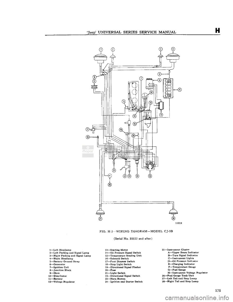
FIG.
H-2—WIRING
DIAGRAM—MODEL
CJ-3B
(Serial No.
35522
and
after)
1—
Left
Headlamp
2—
Left
Parking and Signal Lamp
3— Right Parking and Signal Lamp
4— Right Headlamp 5— Battery Ground Strap
6— Generator 7— Ignition
Coil
8— Junction Block
9—
Horn
10— Distributor
11— Battery
12—
Voltage
Regulator 13— Starting Motor
14—
Oil
Pressure Signal Switch 15— Temperature Sending Unit
16—
Solenoid
Switch 17— Foot Dimmer Switch
18—
Stop
Light Switch 19— Directional Signal Flasher
20— Fuse
21—
Light
Switch 22— Directional Signal Switch
23—
Horn
Button 24— Ignition and Starter Switch 25—Instrument Cluster
A—Upper Beam Indicator
B—Turn
Signal Indicator C—Instrument Lights
D—Oil
Pressure Indicator
E—Charging
Indicator F—Temperature Gauge
G—Fuel
Gauge
H—Instrument
Voltage
Regulator
25—Fuel Gauge Tank Unit
27—
Left
Tail
and
Stop
Lamp
28— Right
Tail
and
Stop
Lamp 175
Page 176 of 376
H
ELECTRICAL
SYSTEM
11474
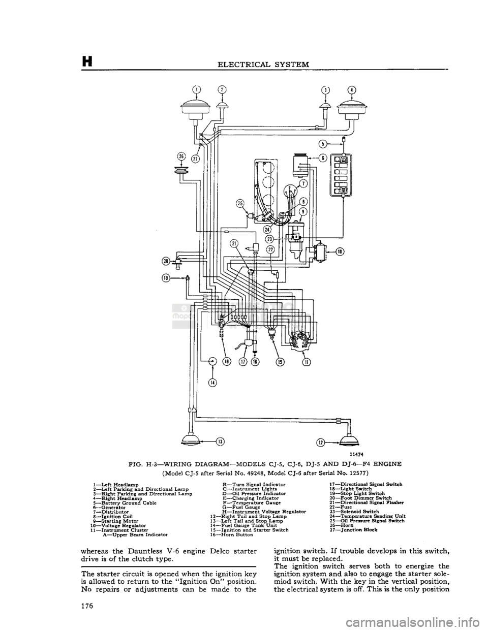
FIG.
H-3—WIRING
DIAGRAM—MODELS
CJ-5, CJ-6, DJ-5 AND DJ-6—F4
ENGINE
(Model CJ-5 after Serial No.
49248,
Model CJ-6 after Serial No.
12577)
1—
Left
Headlamp
B—Turn
Signal Indicator 17—Directional Signal Switch
2—
Left
Parking and Directional Lamp C—Instrument Lights 18—Light Switch
3— Right Parking and Directional Lamp
D—Oil
Pressure Indicator
19—Stop
Light Switch
4— Right Headlamp E—Charging Indicator 20—Foot Dimmer Switch
5— Battery Ground Cable F—Temperature Gauge 21—Directional Signal Flasher
6— Generator
G—Fuel
Gauge 22—Fuse 7— Distributor H—Instrument Voltage Regulator
23—Solenoid
Switch
8— Ignition
Coil
12—Right
Tail
and
Stop
Lamp 24—Temperature Sending Unit
9— Starting Motor 13—Left
Tail
and
Stop
Lamp 25—Oil Pressure Signal Switch
10— Voltage Regulator 14—Fuel Gauge
Tank
Unit 26—Horn
11— Instrument Cluster 15—Ignition and Starter Switch 27—Junction Block
A—Upper
Beam Indicator 16—Horn Button
whereas the Dauntless V-6
engine
Delco starter
ignition
switch. If trouble
develops
in this switch, drive is of the clutch
type.
it must be replaced.
The
ignition
switch
serves
both
to
energize
the
The
starter circuit is
opened
when the
ignition
key
ignition
system
and
also
to
engage
the starter
sole-
is allowed to return to the "Ignition On"
position.
miod switch. With the key in the vertical
position,
No repairs or adjustments can be
made
to the the electrical
system
is off. This is the
only
position
176
Page 177 of 376
'Jeep*
UNIVERSAL
SERIES
SERVICE
MANUAL
H
12968
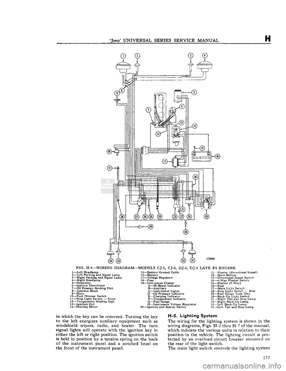
FIG.
H-4—WIRING
DIAGRAM—MODELS
CJ-5, CJ-6, DJ-5, DJ-6
LATE
F4
ENGINE
1—
Left
Headlamp
2—
Left
Parking and Signal Lamp
3— Right Parking and Signal Lamp 4— Right Headlamp
5— Generator
6— Ignition Distributor
7—
Oil
Pressure Sending Unit
8— Junction Block
9—
Horn
10— Foot Dimmer Switch 11—
Stop
Light Switch — Front
12— Temperature Sending Unit
13— Ignition
Coil
14— Starting Motor 15— Battery Ground Cable
16— Battery
17— Voltage Regulator 18—
Fuse
19— Instrument Cluster
A—Hi-Beam
Indicator
B—Auxiliary
C—Instrument
Lights
D—Oil
Pressure Indicator
E—Charging
Indicator
F—Temperature
Indicator
G—Fuel
Gauge
H—Instrument Voltage Regulator
20— Ignition and Starter Switch 21—
Flashei
(Directional Signal)
22—
Horn
Button 23— Directional Signal Switch
24— 4-Way Flasher Switch
25—
Flasher
(4-Way)
26—
Fuse
27—
Main
Light Switch 28—
Stop
Light Switch — Rear
29—
Fuel
Gauge
Tank
Unit
30—
Back-Up
Light Switch
31— Right
Tail
and
Stop
Lamp
32— Right Back-Up Lamp
33—
Left
Back-Up Lamp
34—
Left
Tail
and
Stop
Lamp
in
which the key can be removed. Turning the key
to the
left
energizes
auxiliary
equipment
such as
windshield wipers, radio, and heater. The turn
signal
lights
will
operate
with the
ignition
key in
either the
left
or right
position.
The
ignition
switch is held in
position
by a
tension
spring on the back
of the instrument panel and a
notched
bezel on
the front of the instrument panel.
H-8.
Lighting System
The
wiring for the lighting
system
is shown in the
wiring diagrams, Figs. H-2 thru H-7 of the manual,
which indicate the various units in relation to their
position
in the vehicle. The lighting circuit is pro
tected
by an overload circuit breaker
mounted
on the rear of the light switch.
The
main light switch controls the lighting
system
177
Page 179 of 376
'Jeep'
UNIVERSAL
SERIES
SERVICE
MANUAL
H
12967
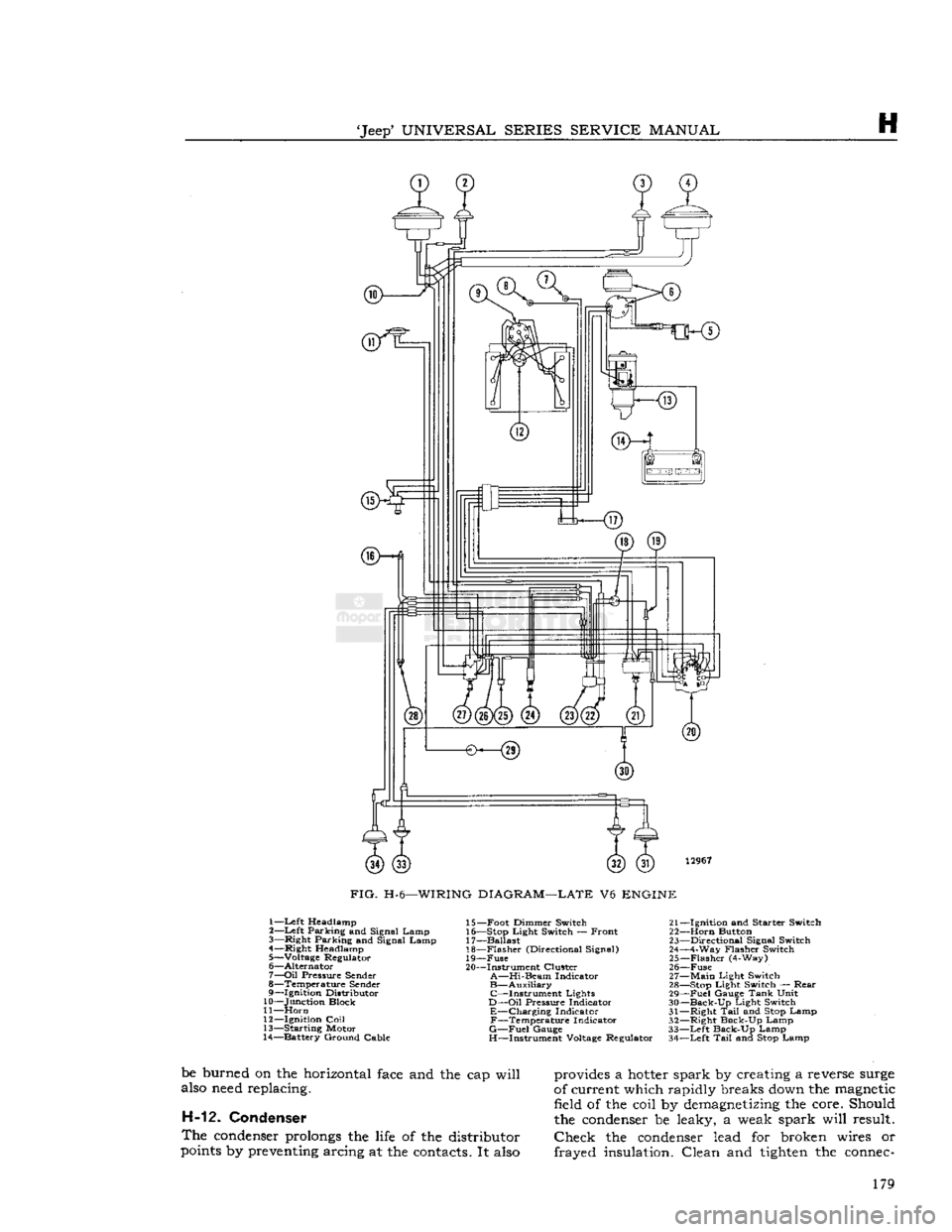
FIG.
H-6—WIRING
DIAGRAM—LATE
V6
ENGINE
1—Left Headlamp
2—
Left
Parking and Signal Lamp
3—
Right
Parking and Signal Lamp
4—
Right
Headlamp
5— Voltage Regulator
6—
Alternator
7—
Oil
Pressure
Sender
8— Temperature
Sender
9—
Ignition
Distributor
10— Junction Block
11—
Horn
12—
Ignition
Coil
13— Starting Motor
14— Battery Ground Cable 15— Foot Dimmer Switch 21-
16— Stop
Light
Switch — Front 22-
17— Ballast 23-
18—
Flasher
(Directional Signal) 24-
19—
Fuse
25-
20— Instrument Cluster 26-
A—Hi-Beam
Indicator 27-
B—Auxiliary
28- C—Instrument Lights 29-
D—Oil
Pressure
Indicator 30-
E—Charging Indicator 31-F—Temperature Indicator 32-
G—Fuel
Gauge
33-
H—Instrument Voltage Regulator 34-
-Ignition
and
Starter
Switch
-Horn
Button
-Directional
Signal Switch
-4-Way
Flasher
Switch
-Flasher
(4-Way)
-Fuse
-Main
Light
Switch
-Stop
Light
Switch —
Rear
-Fuel
Gauge
Tank
Unit
-Back-Up
Light
Switch
-Right
Tail
and Stop Lamp
-Right
Back-Up Lamp
-Left
Back-Up Lamp
-Left
Tail
and Stop Lamp
be burned on the horizontal
face
and the cap will
also
need
replacing. H-12. Condenser
The
condenser
prolongs
the
life
of the distributor
points
by
preventing
arcing at the
contacts.
It
also
provides
a
hotter
spark by creating a reverse
surge
of current which rapidly breaks
down
the
magnetic
field of the coil by
demagnetizing
the core. Should
the
condenser
be leaky, a weak spark will result.
Check
the
condenser
lead for broken wires or
frayed insulation. Clean and
tighten
the
connec-
179
Page 212 of 376
H
ELECTRICAL
SYSTEM
H-124. Testing Indicators and Gauges
Two
gauges
(fuel and temperature) and two in dicators (oil pressure and battery charge) that are
located in the instrument cluster are electrically operated.
The
fuel
gauge
is connected by a single wire to a
float-and-slide-rheostat sending unit in the fuel
tank.
The
temperature
gauge
is connected by a single
wire
to a resistance-type sending unit mounted on the engine.
The
battery charge indicator operates when there
is a difference in potential
between
the generator
and
the battery
.The
battery charge indicator lights
when the generator is not charging the battery. The
indicator
light
goes
out when the generator
begins
to charge the battery.
The
oil pressure indicator is connected by a single
wire
to a diaphragm switch located on the engine.
When
engine
oil pressure is low or zero and the
ignition switch is on, the oil pressure indicator
will
light. When
engine
speed is increased slightly above idle speed, raising the oil pressure to approximately 6 psi. [0,2 kg-cm2], the diaphragm switch
will
open the circuit and the indicator light
will
go out.
A
voltage
regulator maintains a constant
voltage
to the
gauges
in normal operation. On early vehicles,
this
voltage
regulator was mounted on the
rear
of
the instrument cluster. On current vehicles, the
voltage
regulator is integral with the fuel
gauge.
Should
trouble
develop
in the
gauges,
first check the regulator (fuel
gauge
on current production vehicle). If the
voltage
to the regulator is below 10 volts system low
gauge
readings
will
result.
Voltage in
excess
of 16 volts
will
not affect
gauge
readings but may result in premature wear of the
regulator contacts. If the
voltage
to the regulator is
within
the above limits, check the electrical con nections to the regulator (or fuel gauge), especially
the ground connection. If the readings of all the
gauges
is too high, or they all read too low, replace
the regulator (or fuel gauge).
If
the temperature
gauge
or heat indicator in the
instrument cluster have failed, the cause may
originate from the jumper bar shorting out against the instrument case.
Check
the jumper bar
between
the temperature
gauge
and heat indicator at the
rear
of the instrument case. On later production vehicles, the jumper bar is covered with an in
sulating
sleeve
to protect it from shorting out
against the instrument case. If the jumper bar
does
not have this
sleeve,
either install one or
wrap
the bar with plastic electrical tape to
half
an
inch [12,7 mm.] from each end. When installing the jumper bar, be sure the curved
segment
is
closest to the fuel
gauge.
Should
only one of the two
gauges
register incor
rectly,
check the lead wire from the
gauge
to the
sending unit for shorts or open connections. Next disconnect the
gauge
from the sending unit, and
connect the
gauge
to a new fuel tank sending unit
which
has been grounded to the vehicle.
If
the
gauge
registers incorrectly when operating the new unit,
replace the
gauge;
if correctly, replace the sending
unit.
Should
a new fuel tank unit not be available for testing, use a 12-volt
test
light in its place. When
the
gauge
is operating correctly, the pointer
will
move
approximately three-quarters across the
dial.
On
some
vehicles, the temperature
gauge
may
register on or
close
to the H (hot)
mark
when
coolant temperature is
190°F.
to
200°F.
[88°C.
a
93°C.].
In such cases, a 25-ohm,
1-watt
resistor
may be installed on the temperature
gauge
which
will
place the pointer just beyond the center
mark
at a coolant temperature of
190°F.
to
200°F.
Install
the resistor
between
the two terminals on the back
of the
gauge.
Insulate the
exposed
leads of the resistor with electrical tape.
If
the oil pressure indicator
does
not indicate cor
rectly,
first check the light bulb. Next check all
connections and lead wires. If, after all possible
defects
are corrected, the indicator light
does
not go on and off properly, then the diaphragm type
switch in the cylinder block should be replaced.
H-12S.
LIGHTING SYSTEM The
wiring of the lighting systems is shown in
the wiring diagrams, which indicate the various units in relation to their positions in the vehicle.
The
wires in the various circuits are of different
colors or are marked by tracers to aid when check
ing individual circuits.
The
lighting circuits of all models are protected by
an
overload circuit breaker mounted on the back of the main light switch and no replaceable fuse is
required.
The
upper and lower headlight beams are con
trolled by a
foot
switch located on the toe board
to the left of the clutch pedal.
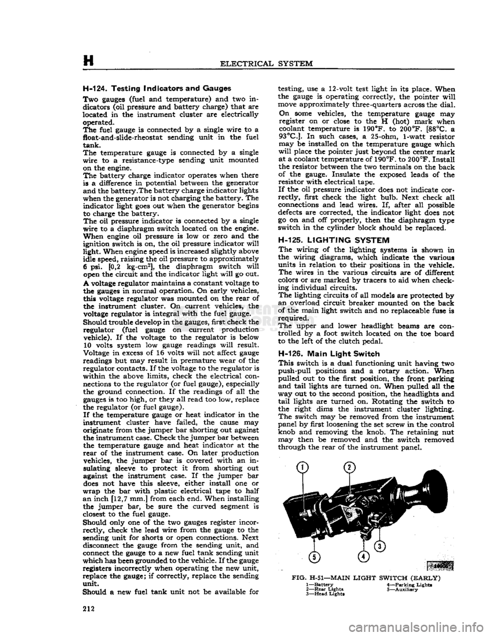
H-126.
Main
Light
Switch
This
switch is a dual functioning unit having two
push-pull
positions and a rotary action. When
pulled out to the first position, the front parking
and
tail
lights are turned on. When pulled all the
way out to the second position, the headlights and
tail
lights are turned on. Rotating the switch to
the right dims the instrument cluster lighting.
The
switch may be removed from the instrument
panel by first loosening the set screw in the control
knob and removing the knob. The retaining nut may then be removed and the switch removed
through the
rear
of the instrument panel.
FIG.
H-51—MAIN
LIGHT
SWITCH
(EARLY)
1—
Battery
4—Parking Lights
2—
Rear
Lights 5—Auxiliary
3—
Head
Lights
212