headlamp JEEP CJ 1953 Service Manual
[x] Cancel search | Manufacturer: JEEP, Model Year: 1953, Model line: CJ, Model: JEEP CJ 1953Pages: 376, PDF Size: 19.96 MB
Page 17 of 376
'Jeep'
UNIVERSAL SERIES SERVICE
MANUAL
B
Reinstall
the axle shafts, and
refill
the housings to
plug level using the universal joint lubricant
specified in
Lubrication
Specifications.
B-56.
Front
Axle Wheel Bearings
To
lubricate the wheel bearings, it is necessary
to remove, clean, repack, and adjust them. When
front wheel hubs and bearings are removed for
lubrication,
they should be thoroughly washed in a
suitable cleaning solvent. The bearings should be
carefully
dried and then given a thorough cleaning
and
inspection. Use a clean brush to remove all
particles
of old lubricant from bearings and hubs.
After
the bearings are cleaned, inspect them for
pitted races and rollers. Also, check the hub oil
seals.
Note:
Wheel bearing lithium base lubricants are
used at the factory for
initial
fill
of
these
bearings.
When
lithium base and sodium base lubricants are
mixed,
the result is a thinned-out mixture that
can
bleed through seals. It is therefore important
that lubricants with the correct base be used when
lubricating
the wheel bearings.
Should
leaks occur at wheel bearing seals, the leaks
may
be caused by a mixture of two
types
of
lubri
cants.
In such cases, the old lubricant should be
completely removed before new lubricant is added.
Wheel
bearings should be thoroughly cleaned,
lubricated
with lithium base and reinstalled.
Repack
the bearing
cones
and rollers with grease
and
reassemble hub in the reverse order of the
disassembly. Test the bearing adjustment as out
lined
in Section Q.
B-57.
Rear
Axle Wheel Bearings
The
Rear
wheel bearings an early models equipped
with
lubrication fittings with a vent opening
through the housings above each fitting should be
lubricated
sparingly, each
2,000
miles
[3.200
km.].
Use
a hand compressor and wheel bearing grease,
forcing
the grease through each lubrication fitting
until
it flows from the vent. Vent should be kept
clear
of obstruction or grease
will
back up into the
brakes.
Do not add grease after it flows from the
vent for it may be forced through the wheel key-
way
onto
the outside of the wheel and possibly
onto
the brake linings.
Rear
wheel bearings that do
not have lubrication fittings should be removed
each
12,000
miles
[19.200
km.] and the bearing
cleaned, inspected and repacked. Refer to proce
dure
in Par. B-56.
Note:
When servicing the Flanged Axle Unit
Bear
ing Assembly, refer to Section N, Par. N-5 for
proper
lubrication procedures.
B-58.
Propeller Shafts
and
Universal Joints
The
propeller shaft slip joints and universals should
be lubricated with a hand compressor grease gun so as to not damage the bearing seals. The units
should be lubricated with a
good
quality grease.
Refer
to the
Lubrication
Chart
for lubrication fre
quency and lubricant type and grade. B-59.
Lights
and
Controls
a.
Check
all interior and exterior lights and light
switches for proper operation, including: parking
lights, headlamps (high beam and low beam),
tail
lights, brake lights, directional lights, and in strument panel lights.
b.
Check
all instrument panel controls and
instru
ments for proper operation.
B-60.
Speedometer Cable
Remove the
speedometer
cable from its housing every
12,000
miles
[19.300
km.].
Clean
it thor
oughly and coat it with a
good
quality light graphite grease.
B-61.
Headlights
Refer
to Section H.
B-62.
Heater Controls
Apply
Lubriplate
130-A to all friction points and
pivot points on the heater controls panel unit as well as the pivot points at the dashpot. Apply
a
few drops of penetrating oil all along the Bowden
cable.
This
oil
will
penetrate into the center wire.
B-63.
Windshield Wiper and
Washer Controls
Lubricate
the friction points and the pivot points
on the windshield wiper transmission and linkage
arms
with a slight amount of
Lubriplate
130-A.
B-64.
Rotate Tires
Refer
to Section Q for the correct method of rotat ing the tires.
B-65.
Body Lube Points
•
Refer to Par. B-66 through B-68.
B-66.
Hood Hinge Pivot Points
Lubricate
the frictional points of the hood hinge
pivot points with a few drops of light-weight
engine
oil.
B-67.
Glove Compartment Door Latch
Sparingly
wipe
Lubriplate
130-A on the
glove
com
partment door latch.
B-68.
Tailgate Hinges
Lubricate
the friction points of the tailgate hinges
with
a few drops of light-weight
engine
oil.
B-69.
LUBRICATION
OF
OPTIONAL EQUIPMENT
B-70.
Pintle Hook
When
lubricating the vehicle, place a few drops of oil on the pintle hook and safety latch pivot pins.
B-7!.
Centrifugal Governor
Check
the oil level in the governor housing at each
vehicle lubrication. Use the same seasonal grade
oil
as is used in the
engine
and change oil at each
engine
oil change. Do not
fill
the housing above
the level indicating plug opening. Keep the vent
in
the filler plug open at all times. 17
Page 175 of 376
'Jeep'
UNIVERSAL
SERIES
SERVICE
MANUAL
H
11514
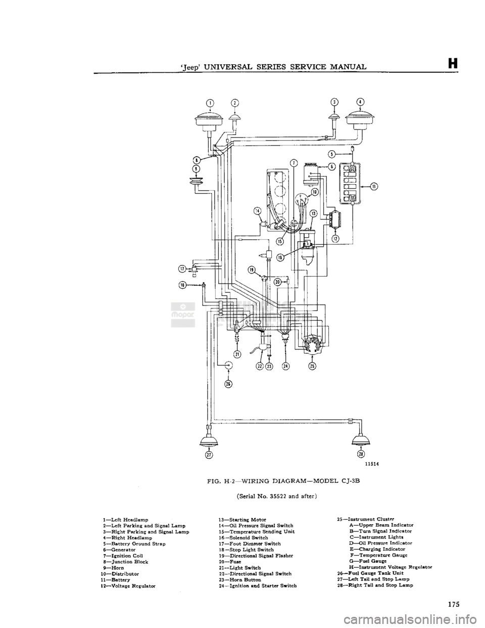
FIG.
H-2—WIRING
DIAGRAM—MODEL
CJ-3B
(Serial No.
35522
and
after)
1—
Left
Headlamp
2—
Left
Parking and Signal Lamp
3— Right Parking and Signal Lamp
4— Right Headlamp 5— Battery Ground Strap
6— Generator 7— Ignition
Coil
8— Junction Block
9—
Horn
10— Distributor
11— Battery
12—
Voltage
Regulator 13— Starting Motor
14—
Oil
Pressure Signal Switch 15— Temperature Sending Unit
16—
Solenoid
Switch 17— Foot Dimmer Switch
18—
Stop
Light Switch 19— Directional Signal Flasher
20— Fuse
21—
Light
Switch 22— Directional Signal Switch
23—
Horn
Button 24— Ignition and Starter Switch 25—Instrument Cluster
A—Upper Beam Indicator
B—Turn
Signal Indicator C—Instrument Lights
D—Oil
Pressure Indicator
E—Charging
Indicator F—Temperature Gauge
G—Fuel
Gauge
H—Instrument
Voltage
Regulator
25—Fuel Gauge Tank Unit
27—
Left
Tail
and
Stop
Lamp
28— Right
Tail
and
Stop
Lamp 175
Page 176 of 376
H
ELECTRICAL
SYSTEM
11474
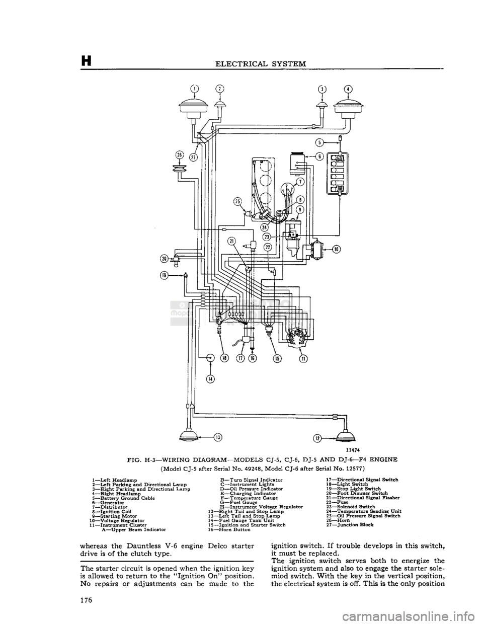
FIG.
H-3—WIRING
DIAGRAM—MODELS
CJ-5, CJ-6, DJ-5 AND DJ-6—F4
ENGINE
(Model CJ-5 after Serial No.
49248,
Model CJ-6 after Serial No.
12577)
1—
Left
Headlamp
B—Turn
Signal Indicator 17—Directional Signal Switch
2—
Left
Parking and Directional Lamp C—Instrument Lights 18—Light Switch
3— Right Parking and Directional Lamp
D—Oil
Pressure Indicator
19—Stop
Light Switch
4— Right Headlamp E—Charging Indicator 20—Foot Dimmer Switch
5— Battery Ground Cable F—Temperature Gauge 21—Directional Signal Flasher
6— Generator
G—Fuel
Gauge 22—Fuse 7— Distributor H—Instrument Voltage Regulator
23—Solenoid
Switch
8— Ignition
Coil
12—Right
Tail
and
Stop
Lamp 24—Temperature Sending Unit
9— Starting Motor 13—Left
Tail
and
Stop
Lamp 25—Oil Pressure Signal Switch
10— Voltage Regulator 14—Fuel Gauge
Tank
Unit 26—Horn
11— Instrument Cluster 15—Ignition and Starter Switch 27—Junction Block
A—Upper
Beam Indicator 16—Horn Button
whereas the Dauntless V-6
engine
Delco starter
ignition
switch. If trouble
develops
in this switch, drive is of the clutch
type.
it must be replaced.
The
ignition
switch
serves
both
to
energize
the
The
starter circuit is
opened
when the
ignition
key
ignition
system
and
also
to
engage
the starter
sole-
is allowed to return to the "Ignition On"
position.
miod switch. With the key in the vertical
position,
No repairs or adjustments can be
made
to the the electrical
system
is off. This is the
only
position
176
Page 177 of 376
'Jeep*
UNIVERSAL
SERIES
SERVICE
MANUAL
H
12968
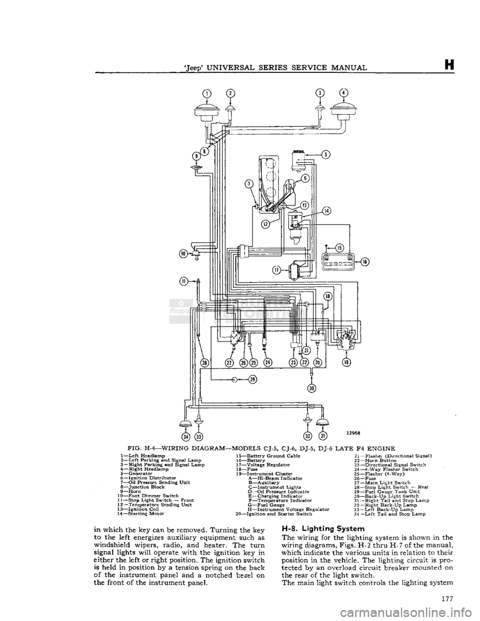
FIG.
H-4—WIRING
DIAGRAM—MODELS
CJ-5, CJ-6, DJ-5, DJ-6
LATE
F4
ENGINE
1—
Left
Headlamp
2—
Left
Parking and Signal Lamp
3— Right Parking and Signal Lamp 4— Right Headlamp
5— Generator
6— Ignition Distributor
7—
Oil
Pressure Sending Unit
8— Junction Block
9—
Horn
10— Foot Dimmer Switch 11—
Stop
Light Switch — Front
12— Temperature Sending Unit
13— Ignition
Coil
14— Starting Motor 15— Battery Ground Cable
16— Battery
17— Voltage Regulator 18—
Fuse
19— Instrument Cluster
A—Hi-Beam
Indicator
B—Auxiliary
C—Instrument
Lights
D—Oil
Pressure Indicator
E—Charging
Indicator
F—Temperature
Indicator
G—Fuel
Gauge
H—Instrument Voltage Regulator
20— Ignition and Starter Switch 21—
Flashei
(Directional Signal)
22—
Horn
Button 23— Directional Signal Switch
24— 4-Way Flasher Switch
25—
Flasher
(4-Way)
26—
Fuse
27—
Main
Light Switch 28—
Stop
Light Switch — Rear
29—
Fuel
Gauge
Tank
Unit
30—
Back-Up
Light Switch
31— Right
Tail
and
Stop
Lamp
32— Right Back-Up Lamp
33—
Left
Back-Up Lamp
34—
Left
Tail
and
Stop
Lamp
in
which the key can be removed. Turning the key
to the
left
energizes
auxiliary
equipment
such as
windshield wipers, radio, and heater. The turn
signal
lights
will
operate
with the
ignition
key in
either the
left
or right
position.
The
ignition
switch is held in
position
by a
tension
spring on the back
of the instrument panel and a
notched
bezel on
the front of the instrument panel.
H-8.
Lighting System
The
wiring for the lighting
system
is shown in the
wiring diagrams, Figs. H-2 thru H-7 of the manual,
which indicate the various units in relation to their
position
in the vehicle. The lighting circuit is pro
tected
by an overload circuit breaker
mounted
on the rear of the light switch.
The
main light switch controls the lighting
system
177
Page 178 of 376
H
ELECTRICAL
SYSTEM
14365
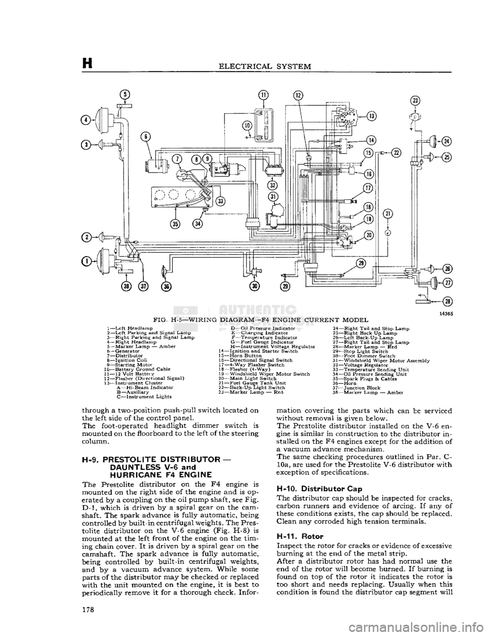
FIG.
H-5—WIRING
DIAGRAM—F4
ENGINE
CURRENT
MODEL
1—
Left
Headlamp
2—
Left
Parking and Signal Lamp
3—
Right
Parking and Signal Lamp
4—
Right
Headlamp
5—
Marker
Lamp
— Amber
6—
Generator
7—
Distributor
8—
Ignition
Coil
9— Starting Motor
10— Battery Ground Cable
11—
12
Volt
Battery
12—
Flasher
(Directional Signal)
13— Instrument Cluster
A—Hi-Beam
Indicator
B—Auxiliary
C—Instrument Lights
D—Oil
Pressure
Indicator
E—Charging Indicator
F—Temperature Indicator
G—Fuel
Gauge
Indicator
H—Instrument Voltage Regulator
14—
Ignition
and
Starter
Switch
15—
Horn
Button 16—
Directional
Signal Switch 17— 4-Way
Flasher
Switch
18—
Flasher
(4-Way)
19—
Windshield
Wiper Motor Switch
20—
Main
Light
Switch
21—
Fuel
Gauge
Tank
Unit
22—
Back-Up
Light
Switch
23—
Marker
Lamp — Red 24—
Right
Tail
and Stop Lamp
25—
Right
Back-Up Lamp
26—
Left
Back-Up Lamp
27—
Right
Tail
and Stop Lamp
28—
Marker
Lamp — Red 29— Stop
Light
Switch
30— Foot Dimmer Switch
31—
Windshield
Wiper Motor Assembly
32—
Voltage Regulator
33— Temperature Sending
Unit
34—
Oil
Pressure
Sending
Unit
35— Spark
Plugs
&
Cables
36—
Horn
37— Junction Block
38—
Marker
Lamp — Amber
through a
two-position
push-pull switch located on
the
left
side
of the control panel.
The
foot-operated
headlight dimmer switch is
mounted on the floorboard to the
left
of the steering
column.
H-9.
PRESTOLITE
DISTRIBUTOR
—
DAUNTLESS
V-6 and
HURRICANE
F4
ENGINE
The
Prestolite distributor on the F4
engine
is
mounted on the right
side
of the
engine
and is op
erated by a coupling on the oil pump shaft, see Fig.
D-l,
which is driven by a spiral gear on the cam
shaft. The spark advance is fully automatic, being controlled by built-in centrifugal
weights.
The Pres
tolite
distributor on the V-6
engine
(Fig. H-8) is mounted at the
left
front of the
engine
on the tim
ing chain cover. It is driven by a spiral gear on the
camshaft. The spark advance is fully automatic,
being controlled by built-in centrifugal
weights,
and by a vacuum advance system. While
some
parts of the distributor may be checked or replaced
with the unit mounted on the
engine,
it is
best
to periodically remove it for a thorough check. Infor mation covering the parts which can be serviced
without removal is
given
below.
The
Prestolite distributor installed on the V-6 en
gine
is similar in construction to the distributor in
stalled on the F4
engines
except
for the addition of
a
vacuum advance mechanism.
The
same checking procedures outlined in Par. C- 10a, are used for the Prestolite V-6 distributor with
exception
of specifications.
H-10. Distributor Cap
The
distributor cap should be inspected for cracks,
carbon runners and
evidence
of arcing. If any of
these
conditions
exists, the cap should be replaced.
Clean
any corroded high
tension
terminals.
H-11.
Rotor
Inspect the rotor for cracks or
evidence
of
excessive
burning at the end of the metal strip.
After a distributor rotor has had normal use the
end of the rotor will
become
burned. If burning is found on top of the rotor it indicates the rotor is
too short and
needs
replacing. Usually when this condition is found the distributor cap
segment
will 178
Page 179 of 376
'Jeep'
UNIVERSAL
SERIES
SERVICE
MANUAL
H
12967
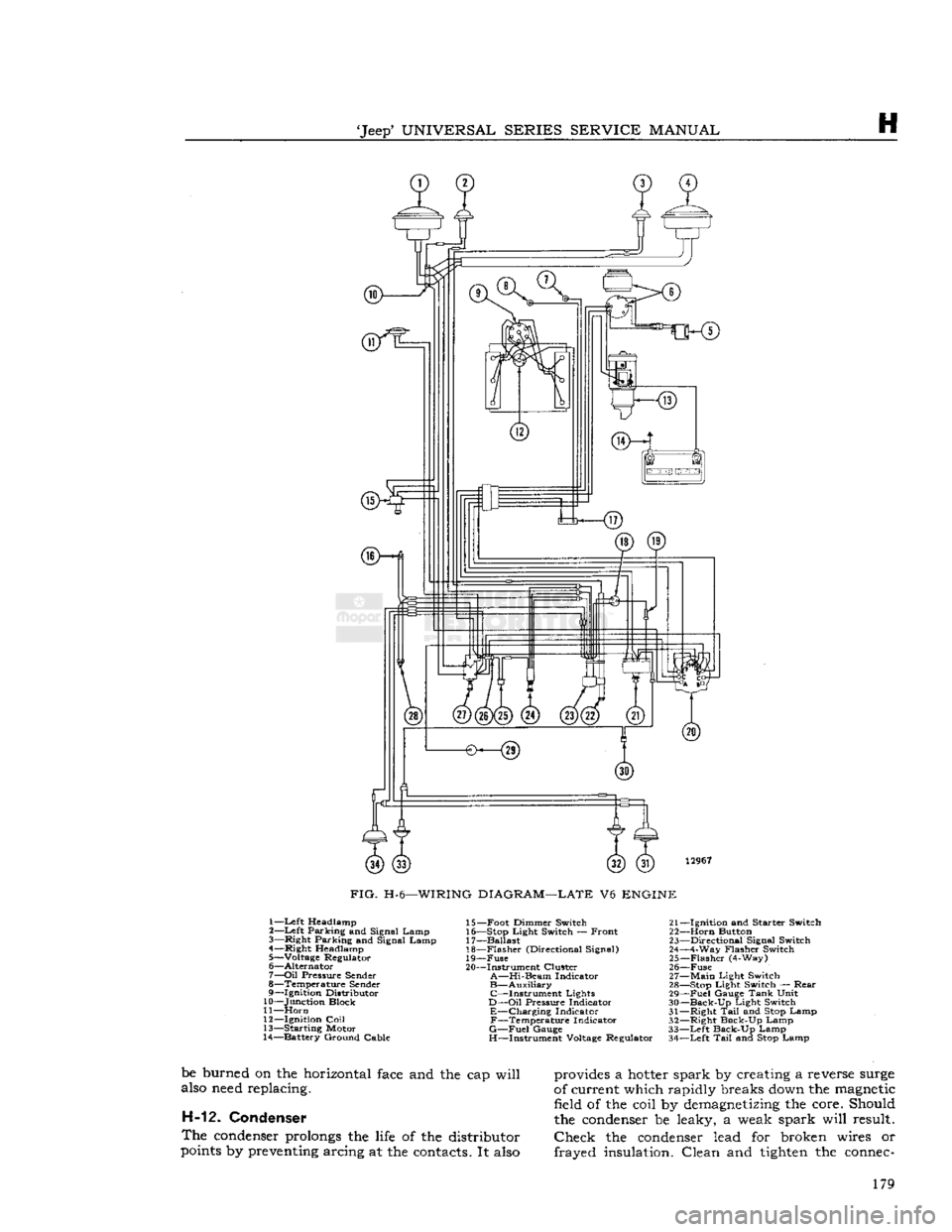
FIG.
H-6—WIRING
DIAGRAM—LATE
V6
ENGINE
1—Left Headlamp
2—
Left
Parking and Signal Lamp
3—
Right
Parking and Signal Lamp
4—
Right
Headlamp
5— Voltage Regulator
6—
Alternator
7—
Oil
Pressure
Sender
8— Temperature
Sender
9—
Ignition
Distributor
10— Junction Block
11—
Horn
12—
Ignition
Coil
13— Starting Motor
14— Battery Ground Cable 15— Foot Dimmer Switch 21-
16— Stop
Light
Switch — Front 22-
17— Ballast 23-
18—
Flasher
(Directional Signal) 24-
19—
Fuse
25-
20— Instrument Cluster 26-
A—Hi-Beam
Indicator 27-
B—Auxiliary
28- C—Instrument Lights 29-
D—Oil
Pressure
Indicator 30-
E—Charging Indicator 31-F—Temperature Indicator 32-
G—Fuel
Gauge
33-
H—Instrument Voltage Regulator 34-
-Ignition
and
Starter
Switch
-Horn
Button
-Directional
Signal Switch
-4-Way
Flasher
Switch
-Flasher
(4-Way)
-Fuse
-Main
Light
Switch
-Stop
Light
Switch —
Rear
-Fuel
Gauge
Tank
Unit
-Back-Up
Light
Switch
-Right
Tail
and Stop Lamp
-Right
Back-Up Lamp
-Left
Back-Up Lamp
-Left
Tail
and Stop Lamp
be burned on the horizontal
face
and the cap will
also
need
replacing. H-12. Condenser
The
condenser
prolongs
the
life
of the distributor
points
by
preventing
arcing at the
contacts.
It
also
provides
a
hotter
spark by creating a reverse
surge
of current which rapidly breaks
down
the
magnetic
field of the coil by
demagnetizing
the core. Should
the
condenser
be leaky, a weak spark will result.
Check
the
condenser
lead for broken wires or
frayed insulation. Clean and
tighten
the
connec-
179
Page 180 of 376
H
ELECTRICAL
SYSTEM
ffKHs)
3—<§)
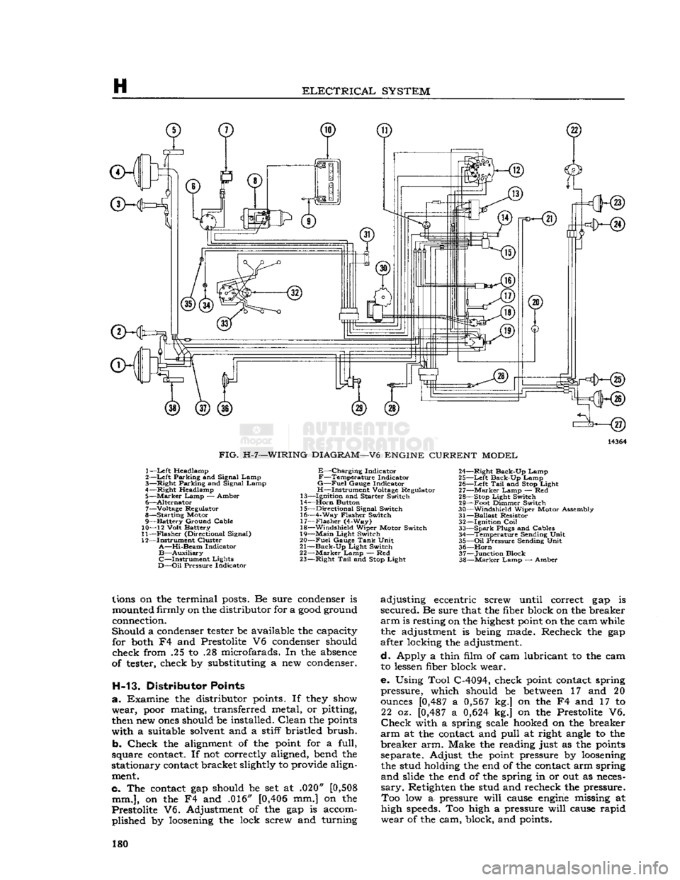
FIG.
H-7—WIRING
DIAGRAM—V6
ENGINE
CURRENT
MODEL
1—
Left
Headlamp
2—Left Parking and Signal Lamp
3— Right Parking and Signal Lamp
4—Right Headlamp 5—
Marker
Lamp — Amber
6— Alternator 7— Voltage Regulator
8— Starting Motor
9— Battery Ground Cable
10— 12 Volt Battery
11—
Flasher
(Directional Signal)
12— Instrument Cluster
A—Hi-Beam
Indicator
B—Auxiliary
C—Instrument
Lights
D—Oil
Pressure Indicator
E—Charging
Indicator
F—Temperature
Indicator
G—Fuel
Gauge Indicator
H—Instrument Voltage Regulator
13— Ignition and Starter Switch
14—
Horn
Button
15— Directional Signal Switch
16— 4-Way Flasher Switch 17—
Flasher
(4-Way)
18— Windshield Wiper Motor Switch
19—
Main
Light Switch
20—
Fuel
Gauge
Tank
Unit
21—
Back-Up
Light Switch
22—
Marker
Lamp — Red
23— Right
Tail
and
Stop
Light 24— Right Back-Up Lamp
25—
Left
Back-Up Lamp 26—
Left
Tail
and
Stop
Light
27—
Marker
Lamp — Red
28—
Stop
Light Switch
29— Foot Dimmer Switch
30— Windshield Wiper Motor Assembly
31—
Ballast
Resistor 32— Ignition
Coil
33—
Spark
Plugs and Cables 34— Temperature Sending Unit
35—
Oil
Pressure Sending Unit 36—
Horn
37— Junction Block
38—
Marker
Lamp — Amber
lions
on the terminal
posts.
Be sure
condenser
is
mounted
firmly on the distributor for a
good
ground
connection.
Should a
condenser
tester
be available the capacity for
both
F4 and Prestolite V6
condenser
should
check from .25 to .28 microfarads. In the
absence
of
tester,
check by substituting a new
condenser.
H-13. Distributor Points
a. Examine the distributor
points.
If
they
show
wear,
poor
mating, transferred metal, or pitting,
then
new
ones
should be installed. Clean the
points
with a suitable
solvent
and a stiff bristled brush.
b. Check the
alignment
of the
point
for a full,
square
contact.
If not correctly aligned, bend the
stationary
contact
bracket slightly to provide align
ment.
c. The
contact
gap should be set at .020"
[0,508
mm.],
on the F4 and .016"
[0,406
mm.] on the
Prestolite V6. Adjustment of the gap is accom plished by
loosening
the lock screw and turning adjusting eccentric screw until correct gap is
secured. Be sure that the fiber block on the breaker
arm
is resting on the
highest
point
on the cam while the adjustment is
being
made. Recheck the gap
after locking the adjustment.
d. Apply a thin film of cam lubricant to the cam to
lessen
fiber block wear.
e. Using Tool C-4094, check
point
contact
spring
pressure, which should be
between
17 and 20
ounces
[0,487
a
0,567
kg.] on the F4 and 17 to 22 oz.
[0,487
a
0,624
kg.] on the Prestolite V6.
Check
with a spring scale
hooked
on the breaker
arm
at the
contact
and pull at right
angle
to the
breaker arm. Make the reading just as the
points
separate. Adjust the
point
pressure by
loosening
the stud holding the end of the
contact
arm spring
and slide the end of the spring in or out as
neces
sary.
Retighten the stud and recheck the pressure. Too low a- pressure will
cause
engine
missing at
high
speeds.
Too high a pressure will
cause
rapid
wear of the cam, block, and
points.
180
Page 221 of 376
'Jeep*
UNIVERSAL
SERIES SERVICE
MANUAL
H
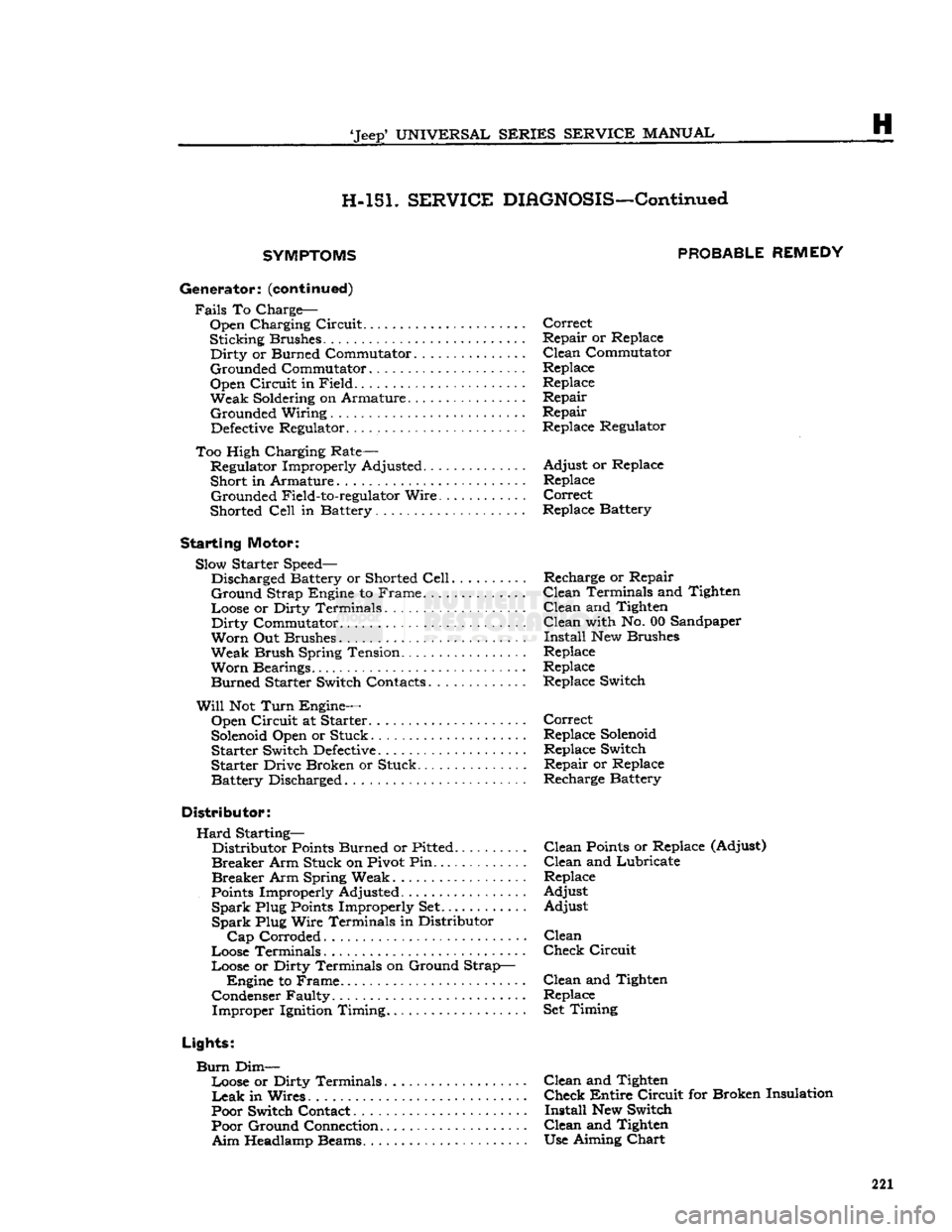
H-151.
SERVICE
DIAGNOSIS—Continued
SYMPTOMS PROBABLE
REMEDY
Generator:
(continued)
Fails
To Charge-Open Charging Circuit Correct
Sticking Brushes Repair or Replace
Dirty
or Burned Commutator ... Clean Commutator
Grounded Commutator Replace
Open Circuit in Field Replace
Weak Soldering on Armature. . . Repair Grounded Wiring Repair
Defective
Regulator. .. Replace Regulator
Too High Charging Rate— Regulator Improperly Adjusted Adjust or Replace
Short in Armature Replace Grounded Field-to-regulator Wire Correct
Shorted
Cell
in Battery... Replace Battery
Starting
Motor: Slow Starter Speed— Discharged Battery or Shorted
Cell
Recharge or Repair
Ground
Strap Engine to Frame. Clean Terminals and Tighten
Loose or Dirty Terminals Clean and Tighten
Dirty
Commutator Clean with No. 00 Sandpaper
Worn
Out Brushes Install New Brushes
Weak Brush Spring Tension Replace
Worn
Bearings Replace Burned Starter Switch Contacts Replace Switch
Will
Not
Turn
Engine— Open Circuit at Starter Correct
Solenoid
Open or Stuck Replace
Solenoid
Starter Switch
Defective
Replace Switch
Starter Drive Broken or Stuck. Repair or Replace
Battery Discharged Recharge Battery
Distributor:
Hard
Starting— Distributor
Points
Burned or Pitted Clean
Points
or Replace (Adjust)
Breaker
Arm Stuck on Pivot Pin...... . ... . . . Clean and Lubricate
Breaker
Arm Spring Weak Replace
Points
Improperly Adjusted Adjust
Spark
Plug
Points
Improperly Set Adjust
Spark
Plug Wire Terminals in Distributor
Cap
Corroded Clean
Loose Terminals Check Circuit
Loose or Dirty Terminals on Ground Strap— Engine to Frame. Clean and Tighten
Condenser Faulty Replace Improper Ignition Timing Set Timing
Lights:
Burn
Dim— Loose or Dirty Terminals....... ........ Clean and Tighten
Leak
in Wires. Check Entire Circuit for Broken Insulation
Poor Switch Contact Install New Switch Poor Ground Connection Clean and Tighten
Aim
Headlamp Beams. Use Aiming
Chart
221