headlight bulb JEEP CJ 1953 Service Manual
[x] Cancel search | Manufacturer: JEEP, Model Year: 1953, Model line: CJ, Model: JEEP CJ 1953Pages: 376, PDF Size: 19.96 MB
Page 212 of 376

H
ELECTRICAL
SYSTEM
H-124. Testing Indicators and Gauges
Two
gauges
(fuel and temperature) and two in dicators (oil pressure and battery charge) that are
located in the instrument cluster are electrically operated.
The
fuel
gauge
is connected by a single wire to a
float-and-slide-rheostat sending unit in the fuel
tank.
The
temperature
gauge
is connected by a single
wire
to a resistance-type sending unit mounted on the engine.
The
battery charge indicator operates when there
is a difference in potential
between
the generator
and
the battery
.The
battery charge indicator lights
when the generator is not charging the battery. The
indicator
light
goes
out when the generator
begins
to charge the battery.
The
oil pressure indicator is connected by a single
wire
to a diaphragm switch located on the engine.
When
engine
oil pressure is low or zero and the
ignition switch is on, the oil pressure indicator
will
light. When
engine
speed is increased slightly above idle speed, raising the oil pressure to approximately 6 psi. [0,2 kg-cm2], the diaphragm switch
will
open the circuit and the indicator light
will
go out.
A
voltage
regulator maintains a constant
voltage
to the
gauges
in normal operation. On early vehicles,
this
voltage
regulator was mounted on the
rear
of
the instrument cluster. On current vehicles, the
voltage
regulator is integral with the fuel
gauge.
Should
trouble
develop
in the
gauges,
first check the regulator (fuel
gauge
on current production vehicle). If the
voltage
to the regulator is below 10 volts system low
gauge
readings
will
result.
Voltage in
excess
of 16 volts
will
not affect
gauge
readings but may result in premature wear of the
regulator contacts. If the
voltage
to the regulator is
within
the above limits, check the electrical con nections to the regulator (or fuel gauge), especially
the ground connection. If the readings of all the
gauges
is too high, or they all read too low, replace
the regulator (or fuel gauge).
If
the temperature
gauge
or heat indicator in the
instrument cluster have failed, the cause may
originate from the jumper bar shorting out against the instrument case.
Check
the jumper bar
between
the temperature
gauge
and heat indicator at the
rear
of the instrument case. On later production vehicles, the jumper bar is covered with an in
sulating
sleeve
to protect it from shorting out
against the instrument case. If the jumper bar
does
not have this
sleeve,
either install one or
wrap
the bar with plastic electrical tape to
half
an
inch [12,7 mm.] from each end. When installing the jumper bar, be sure the curved
segment
is
closest to the fuel
gauge.
Should
only one of the two
gauges
register incor
rectly,
check the lead wire from the
gauge
to the
sending unit for shorts or open connections. Next disconnect the
gauge
from the sending unit, and
connect the
gauge
to a new fuel tank sending unit
which
has been grounded to the vehicle.
If
the
gauge
registers incorrectly when operating the new unit,
replace the
gauge;
if correctly, replace the sending
unit.
Should
a new fuel tank unit not be available for testing, use a 12-volt
test
light in its place. When
the
gauge
is operating correctly, the pointer
will
move
approximately three-quarters across the
dial.
On
some
vehicles, the temperature
gauge
may
register on or
close
to the H (hot)
mark
when
coolant temperature is
190°F.
to
200°F.
[88°C.
a
93°C.].
In such cases, a 25-ohm,
1-watt
resistor
may be installed on the temperature
gauge
which
will
place the pointer just beyond the center
mark
at a coolant temperature of
190°F.
to
200°F.
Install
the resistor
between
the two terminals on the back
of the
gauge.
Insulate the
exposed
leads of the resistor with electrical tape.
If
the oil pressure indicator
does
not indicate cor
rectly,
first check the light bulb. Next check all
connections and lead wires. If, after all possible
defects
are corrected, the indicator light
does
not go on and off properly, then the diaphragm type
switch in the cylinder block should be replaced.
H-12S.
LIGHTING SYSTEM The
wiring of the lighting systems is shown in
the wiring diagrams, which indicate the various units in relation to their positions in the vehicle.
The
wires in the various circuits are of different
colors or are marked by tracers to aid when check
ing individual circuits.
The
lighting circuits of all models are protected by
an
overload circuit breaker mounted on the back of the main light switch and no replaceable fuse is
required.
The
upper and lower headlight beams are con
trolled by a
foot
switch located on the toe board
to the left of the clutch pedal.
H-126.
Main
Light
Switch
This
switch is a dual functioning unit having two
push-pull
positions and a rotary action. When
pulled out to the first position, the front parking
and
tail
lights are turned on. When pulled all the
way out to the second position, the headlights and
tail
lights are turned on. Rotating the switch to
the right dims the instrument cluster lighting.
The
switch may be removed from the instrument
panel by first loosening the set screw in the control
knob and removing the knob. The retaining nut may then be removed and the switch removed
through the
rear
of the instrument panel.
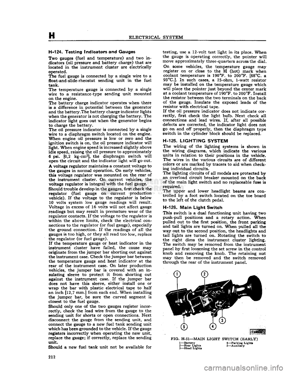
FIG.
H-51—MAIN
LIGHT
SWITCH
(EARLY)
1—
Battery
4—Parking Lights
2—
Rear
Lights 5—Auxiliary
3—
Head
Lights
212
Page 213 of 376

'Jeep'
UNIVERSAL
SERIES SERVICE
MANUAL
H
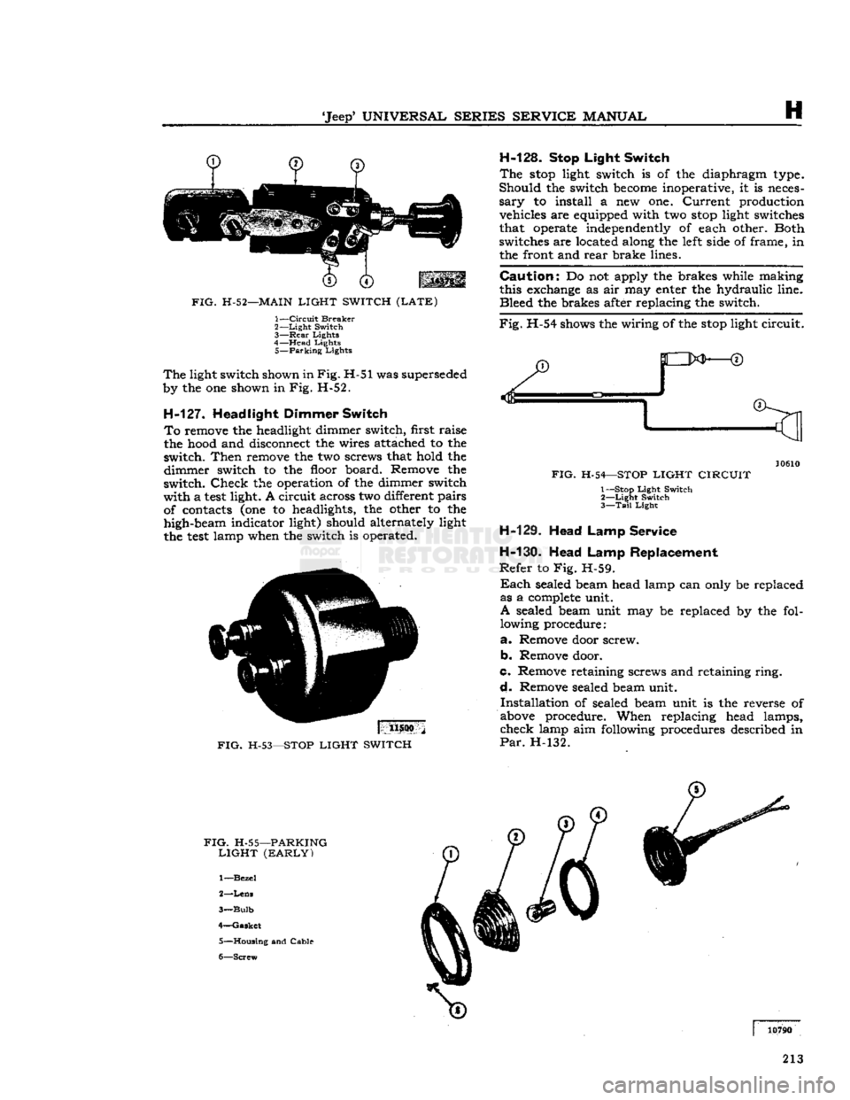
FIG.
H-52—MAIN
LIGHT SWITCH (LATE)
1—
Circuit
Breaker
2—
Light
Switch
3—
Rear
Lights
4—
Head
Lights
5—
Parking
Lights
The
light switch shown in
Fig.
H-51 was superseded
by the one shown in
Fig.
H-52.
H-127.
Headlight Dimmer Switch To
remove the headlight dimmer switch, first raise
the hood and disconnect the wires attached to the
switch.
Then
remove the two screws that hold the
dimmer
switch to the floor board. Remove the
switch.
Check
the operation of the dimmer switch
with
a
test
light. A
circuit
across two different pairs of contacts (one to headlights, the other to the
high-beam indicator light) should alternately light
the
test
lamp when the switch is operated.
H-128.
Stop Light Switch
The
stop
light switch is of the diaphragm type.
Should
the switch
become
inoperative, it is neces
sary
to install a new one.
Current
production vehicles are equipped with two
stop
light switches
that operate independently of each other. Both
switches are located along the
left
side of frame, in the front and
rear
brake lines.
Caution:
Do not apply the brakes while making
this exchange as air may enter the hydraulic line.
Bleed
the brakes after replacing the switch.
Fig.
H-54 shows the wiring of the
stop
light
circuit.
11500
FIG.
H-53—STOP
LIGHT SWITCH
FIG.
H-54—STOP
LIGHT CIRCUIT
1— Stop
Light
Switch
2—
Light
Switch
3—
Tail
Light
H-129. Head Lamp Service
H-130.
Head Lamp Replacement
Refer
to Fig. H-59.
Each
sealed beam head lamp can only be replaced as a
complete
unit.
A
sealed beam unit may be replaced by the fol lowing procedure:
a.
Remove door screw.
b.
Remove door.
c.
Remove retaining screws and retaining
ring.
d.
Remove sealed beam unit.
Installation
of sealed beam unit is the reverse of
above procedure. When replacing head lamps,
check
lamp aim following procedures described in
Par.
H-132.
FIG.
H-55—PARKING
LIGHT (EARLY)
1—
Bezel
2—
Lens
3—
Bulb
4—
Gasket
5—
Housing
and Cable
6—
Screw
213
Page 224 of 376

H
ELECTRICAL
SYSTEM
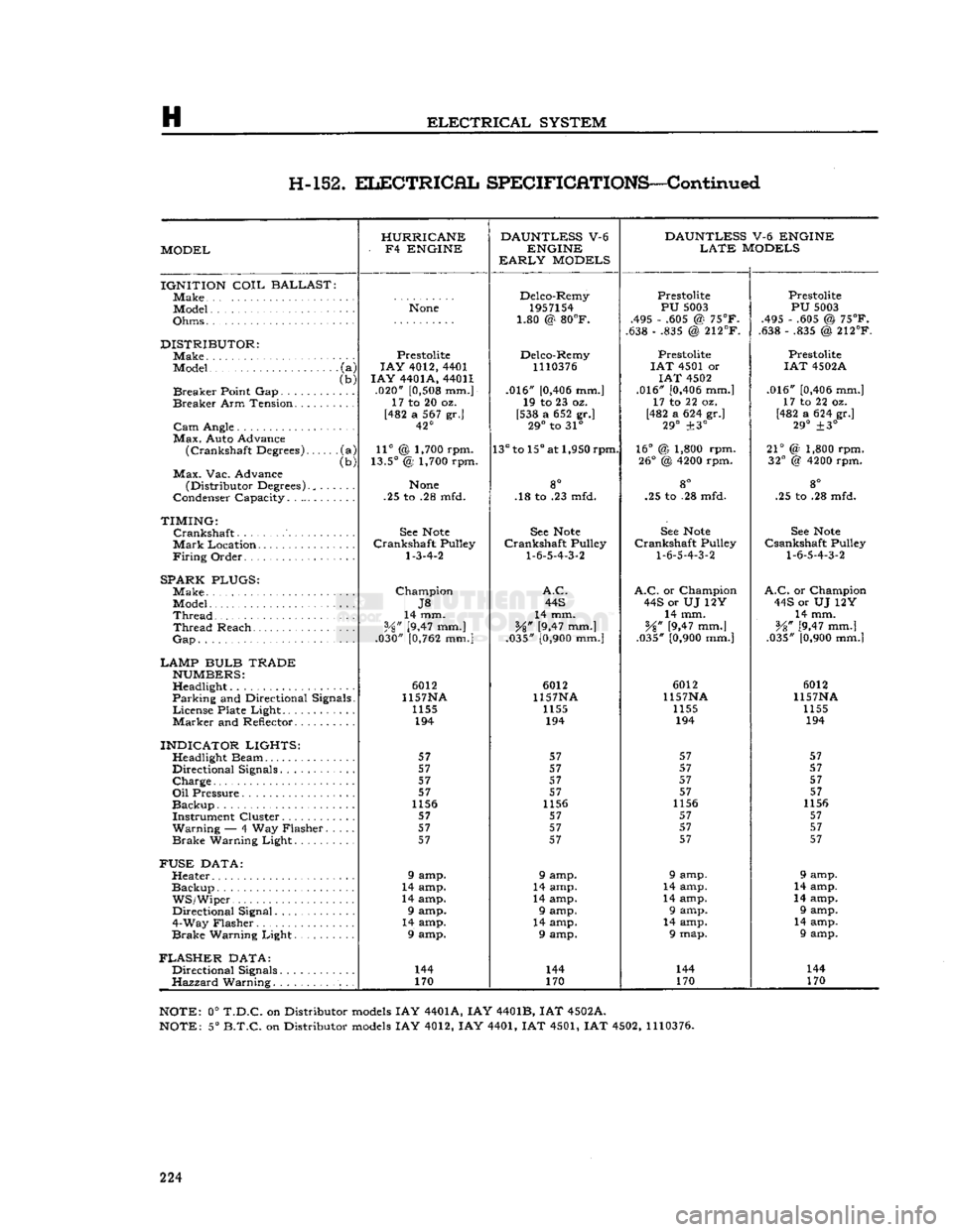
H-152.
ELECTRICAL
SPECIFICATIONS—Continued
HURRICANE DAUNTLESS
V-6
DAUNTLESS
V-6 ENGINE
MODEL -
F4
ENGINE
ENGINE
LATE
MODELS
EARLY
MODELS
IGNITION
COIL
BALLAST
]Make Delco-Remy
Prestolite Prestolite
Model
None
1957154
PU
5003
PU
5003
Ohms • • 1.80 @
80°F.
.495 - .605 @
75°F.
.495 - .605 @
75°F.
1.80 @
80°F.
.638 - .835 @
212°F.
.638 - .835 @
212°F.
DISTRIBUTOR:
Prestolite Delco-Remy Prestolite Prestolite
Model
•
(a)
LAY
4012, 4401
1110376
I
AT
4501 or
IAT
4502A
(b)
I
AY
4401A, 44011
IAT
4502
Breaker
Point Gap (b)
.020"
[0,508
mm.] .016"
[0,406
mm.] .016"
[0,406
mm.]
.016"
[0,406
mm.]
Breaker
Arm Tension. ..... 17 to 20 oz.
19 to 23 oz. 17 to 22 oz. 17 to 22 oz.
[482 a 567 gr.] [538 a 652 gr.] [482 a 624 gr.]
[482 a 624 gr.]
42° 29°
to 31°
29°
±3°
29°
±3°
Max.
Auto Advance
(Crankshaft
Degrees) •(a)
11°
@ 1,700 rpm.
13°
to
15°
at 1,950 rpm.
16°
@ 1,800 rpm.
21°
(2 1,800 rpm.
(Crankshaft
Degrees)
(b)
13.5°
@ 1,700 rpm.
26°
@
4200
rpm.
32°
@
4200
rpm.
Max.
Vac. Advance go
(Distributor Degrees)., . .
None
8° 8°
go
Condenser Capacity. . .25 to .28 mfd. .18 to .23 mfd. .25 to .28 mfd. .25 to .28 mfd.
TIMING:
Crankshaft
See
Note
See
Note
See
Note
See
Note
Mark
Location............
Crankshaft
Pulley
Crankshaft
Pulley
Crankshaft
Pulley
Csankshaft
Pulley
Firing
Order
1-3-4-2
1-6-5-4-3-2
1-6-5-4-3-2 1-6-5-4-3-2
SPARK PLUGS:
Make
Champion
A.C. A.C.
or Champion
A.C.
or Champion
J8
44S
44S or UJ 12Y 44S or UJ 12Y
Thread
14 mm.
14 mm. 14 mm. 14 mm.
Thread
Reach
Vz"
[9,47 mm.]
%"
[9,47 mm.]
¥%"
[9,47 mm.]
V8" [9,47 mm.]
Gap
.030"
[0,762
mm.]
.035"
[0,900
mm.] .035"
[0,900
mm.] .035"
[0,900
mm.|
LAMP BULB TRADE
NUMBERS:
Headlight 6012
6012 6012 6012
Parking
and Directional Signals. 1157NA
1157NA 1157NA 1157NA
License
Plate Light........ 1155
1155 1155 1155
Marker
and Reflector 194
194 194 194
INDICATOR LIGHTS:
57 57 57 57
Directional Signals........ 57
57 57 57
Charge
57
57 57 57
57 57 57 57
1156 1156 1156 1156
Instrument Cluster 57 57 57 57
Warning
— 4 Way Flasher. . 57
57 57 57
Brake
Warning Light 57
57 57 57
FUSE
DATA:
Heater 9 amp. 9 amp. 9 amp. 9 amp.
Backup
14 amp. 14 amp. 14 amp. 14 amp.
WS/Wiper.
14 amp. 14 amp. 14 amp. 14 amp.
Directional Signal 9 amp. 9 amp. 9 amp. 9 amp.
4-Way Flasher 14 amp. 14 amp. 14 amp. 14 amp.
Brake
Warning Light 9 amp. 9 amp. 9 map. 9 amp.
FLASHER
DATA:
Directional Signals. 144
144 144 144
Hazzard
Warning. 170
170 170 170
NOTE:
0°
T.D.C.
on Distributor
models
IAY 4401A, IAY 4401B, IAT 4502A.
NOTE:
5°
B.T.C.
on Distributor
models
IAY 4012, IAY 4401, IAT 4501, IAT 4502,
1110376.
224