tow bar JEEP CJ 1953 Service Manual
[x] Cancel search | Manufacturer: JEEP, Model Year: 1953, Model line: CJ, Model: JEEP CJ 1953Pages: 376, PDF Size: 19.96 MB
Page 30 of 376
c
TUNE-UP
meter during this
test
Connect the red lead
tc*
dis
tributor
primary
lead at the coil as shown in Fig.
C-21.
Connect black lead to the ground.
Turn
ignition switch on; with
engine
stopped, observe
dwell
meter. If the meter reads zero,
crank
the
engine
a fraction of a revolution to
close
the
breaker
points.
Distributor
resistance is normal, if dwell meter
pointer is within range of
black
bar. Distributor resistance is high, if
dwell
meter pointer is not
within
the black bar.
Remove test lead from
distri
butor terminal of coil and
connect
to
each
of the
following points to determine
where
the excessive resistance is:
Distributor
primary
terminal
Distributor
primary
terminal in the distributor
Breaker
point bracket
Ground
side of points
Distributor
housing
Where
a noticeable change occurs in the meter
reading
in
these
steps, make the necessary correc
tion and repeat the
test.
C-l 7. Distributor
Point
Dwell
Using
a dwell tester, connect red
lead
to the
distri
butor terminal at coil. Connect black lead to
ground.
Set selector switch to the number of
cylin
ders in the
engine
being tested. Operate
engine
speed at specified rpm. and
note
readings. Cam
dwell
angle must be 30° for the Dauntless V-6
Delco equipped engine, 29° ±: 3° Prestolite equipped
engine
and 42° for the
Hurricane
F4 engine. If the dwell reading is not to specifications,
trouble could be improper point spacing, point
rubbing,
defective block or breaker arm, or mis
aligned and worn distributor cam.
Adjust
dwell
as shown in Fig. C-14 for the Delco equipped
Dauntless V-6 engine. For cam dwell adjustment
of the Prestolite equipped V6 and
Hurricane
F4 engine, refer to Par. C-10,
step
a.
Dwell
variation is determined by noting any
dwell
change as the
engine
is operated at different
speeds.
Excessive
variation indicates a change in point opening that can result from shaft or bushing wear,
or
from the distributor plate shifting because of
wear
or
looseness.
Measure
dwell variation at idle speed, using same
test
hookup for checking dwell. Increase speed to 1750 rpm.;
note
dwell reading.
Then
slowly reduce
speed to idle while observing dwell meter. Dwell
variation
should not exceed 3°. If dwell variation
exceeds
3°
between
idle speed and 1750 rpm.,
probable wear in the distributor shaft, bushings, or
breaker
plate is indicated. Distributor should then be checked more thoroughly.
C-l8. Check Ignition Wires
and
Connections
Examine
and clean the insulation on all ignition
wires
and check all connections. Wires should be
firm,
flexible, and free from roughness and minute
cracks.
Bend wires to check for brittle,
cracked,
or
loose
insulation. Since defective insulation
will
per
mit
crossfiring or missing of the engine, defective
wires
should be replaced.
C-l9. Test Ignition
Cables
To
remove cables from
spark
plugs, use
Spark
Plug
Cable
Remover
Tool
W-274.
Twist
the
boot
slightly to break the seal and, grasping the rubber
protector
boot,
lift straight up with a steady even
pull.
Do not grasp the cable and
jerk
the cable off; this
will
damage the cables. Do not use a probe
on
these
wires; puncturing them may cause a
separation in the conductor. To remove ignition cables from the distributor cap or coil tower,
loosen
the nipple first, then grasp the upper part of the nipple and the cable and gently
pull
straight up.
Test
the cable with an ohmmeter. Resistance value
per
foot
is
3000-7000
ohms. The ignition cables
can
be checked for
circuit
continuity by removing
the cable from the
spark
plug and holding the cable
end Vi" [6,35 mm.] from the engine. A strong
spark
indicates
good
conductor continuity.
When
connecting the cable to the
spark
plug, be
certain
a
good
connection is made and that the
protector
boot
fits tight on the
spark
plug. A
partially
seated cable creates an additional gap in
the
circuit
and the resulting
spark
jump
will
cause
terminal
corrosion and cable damage.
C-20. Coil
When
an ignition coil is suspected of being defec tive, it should be checked on the car. A coil may
break
down after it has reached operating tempera
ture.
It is important that the coil be at operating
temperature when
tests
are made.
Note:
The ignition coil and ballast resistor for the
V-6
engine
must be of the same manufacturer.
Ballast
resistors and ignition coils of one manufac
turer
are interchangeable with both units of the
other.
C-21.
Service Air
Cleaner
Refer
to Par.
B-2 2
for the correct service of the
air
cleaner.
C-22.
Check Fuel Lines and
Screens
Check
all fuel line connections to guard against
leakage.
Check
fuel pump filter F4
engine
and
fuel
line filter V-6 engine. Replace fuel filter if
necessary.
C-23. Check Fuel Pump a.
Fuel
pump pressure is important, for low pres
sure
will
seriously affect
engine
operation and high
pressure
will
cause excessive fuel consumption and
possibly flood the carburetor. Should there be any doubt of normal operation, check the pressure with
a
gauge
as shown in Fig.
C-2 2.
The minimum and
maximum
allowable pressures are 2% to 3% lbs. [0,176 a
0,264
kg-cm2], for the
Hurricane
F4 en
gine.
Fuel
pump pressure at carburetor (inlet) on
the Dauntless V6-225
engine
should be 3% lbs.
[0,264
kg-cm2] minimum at specified
R.P.M.
idle
with
the vapor
return
hose
squeezed off.
With
the
vapor
return
hose
open pump pressure should be
2
V2
lbs. [0,176 kg-cm2] minimum.
b.
Test for volume, as a pump may build up suffi
cient pressure but
fail
to produce sufficient volume.
Turn
down the carburetor fuel line fitting on the
pump and with the tank line connected, pump out
30
Page 42 of 376
D
HURRICANE
F4
ENGINE
D-7.
Remove Water Pump
Remove the
bolts
and lockwashers that attach the
water pump to the cylinder block. Remove the water pump.
D-8.
Remove
Exhaust
Manifold
Remove the five nuts from the manifold studs.
Pull
the manifold off the mounting studs. Remove the center and two end gaskets from the cylinder
block. See Section Fl for exhaust emission con trolled engines.
D-9.
Remove Oil
Filler
Tube
Loop
a piece of wire several times around the tube
below the top and make a
loop
through which a
pry
bar may be used to pry over the top of the
engine
water
outlet
fitting.
Pull
on the tube, tapping it just above where it enters the crankcase.
D-10.
Remove Water Outlet Fitting
Remove the nuts and lockwashers that attach the
water
outlet
fitting to the cylinder head.
Lift
the
outlet
fitting from the cylinder head.
D-11.
Remove Thermostat
With
the water
outlet
fitting removed, the thermo
stat can be lifted from the water
outlet
elbow on the cylinder head.
D-12.
Remove
Crankshaft
Pulley
Remove the crankshaft nut.
Install
a puller and
pull
the pulley from the crankshaft.
D-13.
Remove Distributor
a.
Remove
spark
plug cables from the distributor
cap,
noting the order in which they are assembled to ensure correct reassembly. No. 1
spark
plug
terminal
is in the 5 o'clock position. Starting with this tower the cables are installed in a counterclockwise direction in
1-3-4-2
firing order.
b.
Remove the
primary
lead from the terminal
post
at the side of the distributor.
c. Remove the screw holding the distributor to the crankcase and lift the assembly from the engine.
D-14. Remove Oil Pump
The
oil pump is located externally on the left side
of the engine. If only the oil pump is being removed
with
the
engine
in the vehicle, set No. 1 piston at
TDC
for reference for reinstalling the oil pump
without greatly disturbing the ignition timing.
First
remove the distributor cover and
note
the
position of the distributor rotor.
If
the distributor is already removed, sight through
the distributor
hole
before removing the oil pump.
The
slot should be near vertical. Remove the capscrews and lockwashers attaching the oil pump
to the cylinder block.
Carefully
slide the oil pump
and
its drive shaft out of the cylinder block.
D-1S.
Remove
Crankcase
Ventilation Valve
To
remove the crankcase ventilation valve from
the elbow fitting screwed into the inlet manifold of the cylinder head, first remove the
hose
and
clamp from the valve (Fig. D-32), then using a
wrench
carefully unscrew the valve from the
elbow.
D-l6.
Remove Rooker Arm Assemblies
The
rocker arm cover was previously removed as
a
step
of the
engine
removal (Par. D-5).
Remove the nuts from the rocker arm shaft support
studs, and lift the rocker arm assembly off the studs.
Lift
the intake valve push rods out of the
cylinder
block.
D-17.
Remove
Cylinder
Head
a.
Removal.
Disconnect the oil line from the flared tube con
nector and remove the rocker arm attaching stud nuts, and rocker arm shaft assembly if not pre
viously removed. Two end head
bolts
cannot be removed until the rocker arm shaft is removed.
Remove the cylinder head bolts.
There
is one
cylinder
head bolt located below the carburetor
mounting, inside the intake manifold, that must
not be overlooked.
Carefully
lift the cylinder head off the block.
Remove the valve push rods and the valve lifters.
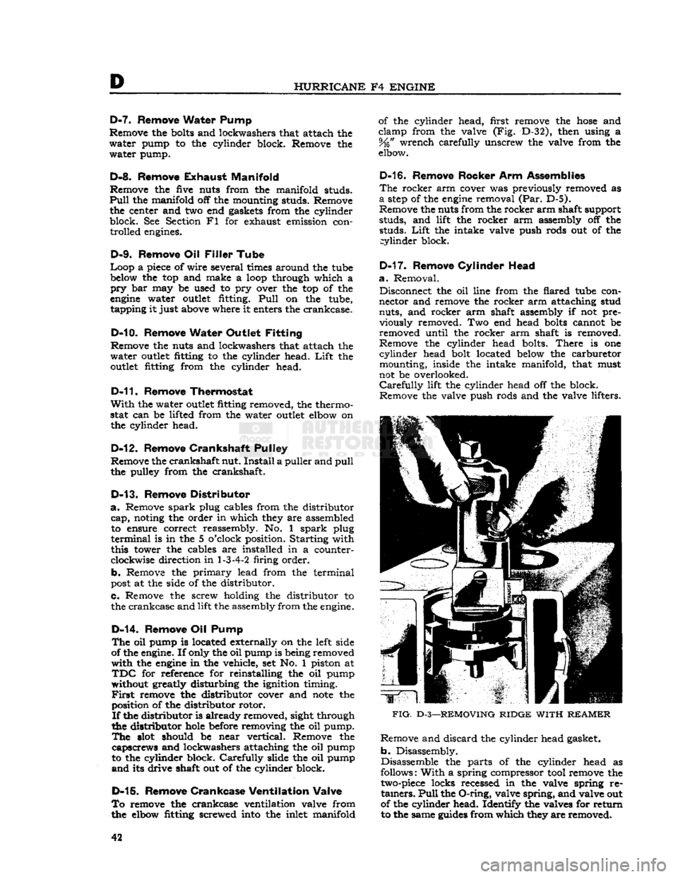
FIG.
D-3—REMOVING
RIDGE
WITH
REAMER
Remove and discard the cylinder head gasket,
b. Disassembly.
Disassemble the parts of the cylinder head as
follows:
With
a spring compressor tool remove the
two-piece
locks recessed in the valve spring re
tainers.
Pull
the
O-ring,
valve spring, and valve out
of the cylinder head. Identify the valves for return to the same
guides
from which they are removed.
42
Page 262 of 376
Jl
FOUR-SPEED
TRANSMISSION
U.
On the T-98 transmission remove the snap rings
holding the thrust washer, bearing rollers, second-
speed
gear, and spacer on the mainshaft. Slide
these
components
off the shaft. Refer to Fig. Jl-3.
Note:
The second
speed
gear in the T-18 trans
mission is a slide fit
onto
the mainshaft and
does
not contain roller bearings or a spacer.
v. If the synchronizer assemblies are to be dis
assembled and serviced proceed as follows:
Wrap
the
second-speed
synchronizer assembly in a cloth
to prevent losing the lock balls and springs. Push the clutch hub out of the low-and-second-speed
gear in a direction
opposite
the shift fork
groove.
Remove the cloth.
Lift
the balls, springs, and
plates out of the hub.
w. Remove the lockplate for the countershaft and
reverse idler gear shaft.
x.
Use a pry bar in the
slot
of the reverse idler gear
shaft to
loosen
the shaft.
Then,
slip the reverse
idler
gear shaft out of the housing and gear.
Lift
the reverse idler gear assembly from the transmission case.
y. To remove the countershaft, use a heavy brass
drift
and drive the countershaft toward the
rear
of
the transmission case. When the countershaft end
is just about even with the inside of the trans mission case, use a dummy shaft to force it the
remainder of the way. (Since a dummy shaft is a
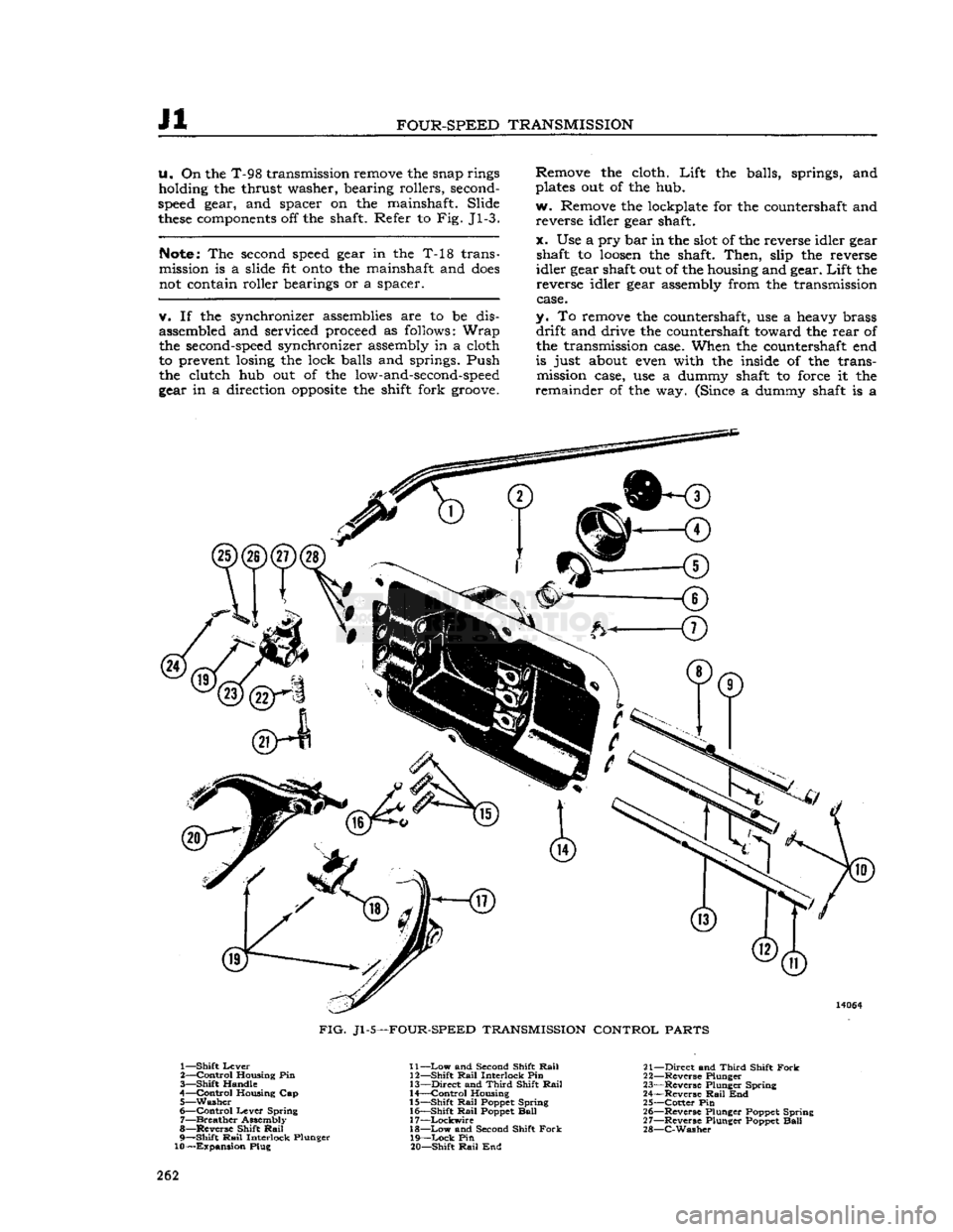
FIG.
Jl -5—FOUR-SPEED TRANSMISSION CONTROL PARTS
1—
Shift
Lever
2—
Control
Housing Pin
3—
Shift
Handle
4—
Control
Housing Cap 5—
Washer
6—
Control
Lever
Spring
7—
Breather
Assembly
8— Reverse Shift
Rail
9—
Shift
Rail
Interlock Plunger
10—Expansion
Plug 11—
Low
and Second Shift
Rail
12—
Shift
Rail
Interlock Pin
13—
Direct
and
Third
Shift
Rail
14—
Control
Housing
15—
Shift
Rail
Poppet Spring
16—
Shift
Rail
Poppet
Ball
17—
Lockwire
18—
Low
and Second Shift
Fork
19—
Lock
Pin
20—
Shift
Rail
End 21—
Direct
and
Third
Shift
Fork
22— Reverse Plunger
23— Reverse Plunger Spring
24— Reverse
Rail
End
25—
Cotter
Pin
26— Reverse Plunger Poppet Spring
27— Reverse Plunger Poppet
Ball
28—
C-Washer
262
Page 304 of 376
N
REAR
AXLE
With
the
Trac-Lok
unit removed from the axle
housing, proceed as follows:
N-29.
Disassembly
a.
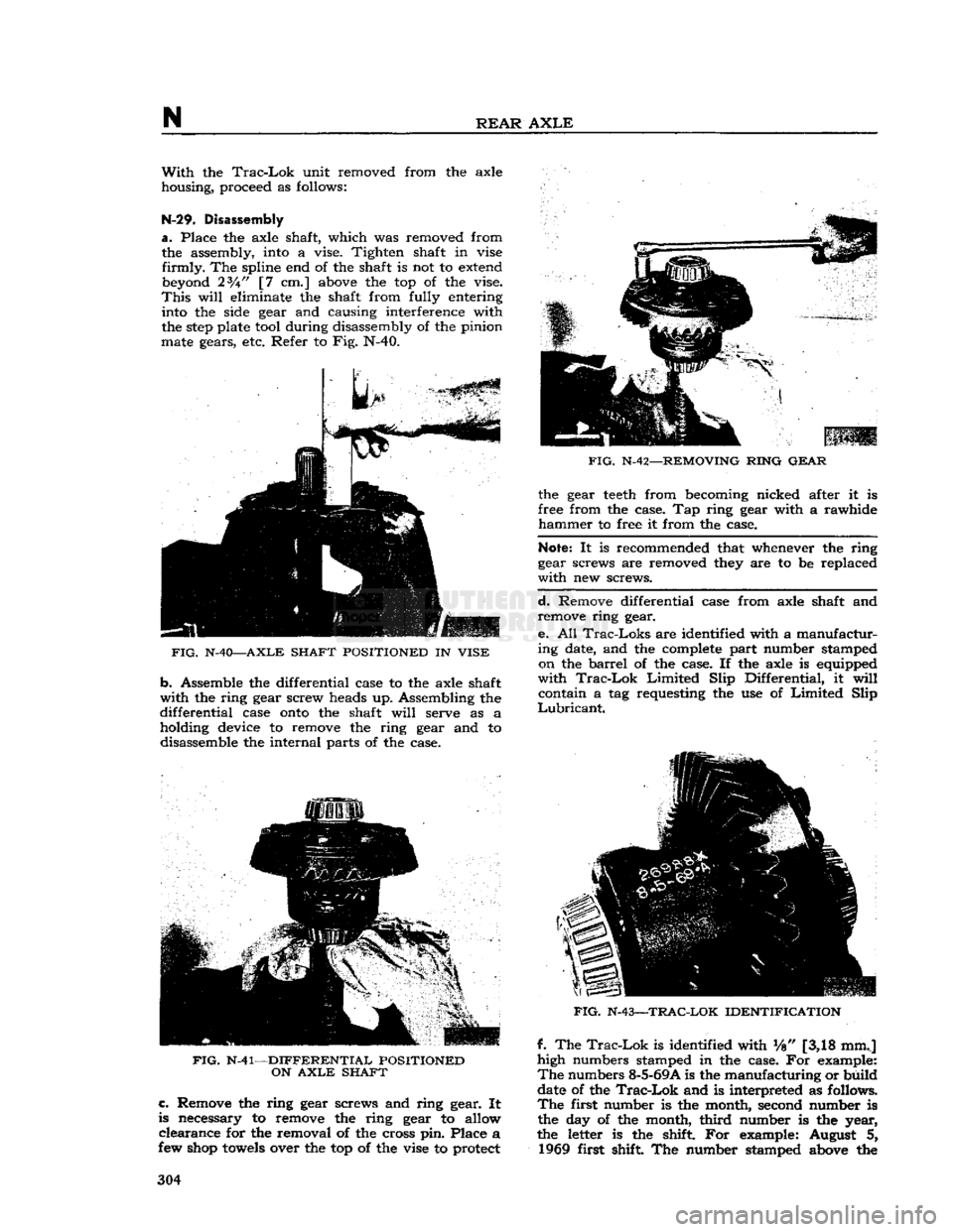
Place the axle shaft, which was removed from the assembly, into a vise. Tighten shaft in vise
firmly.
The spline end of the shaft is not to extend beyond 23A" [7 cm.] above the top of the vise.
This
will
eliminate the shaft from fully entering into the side gear and causing interference with
the
step
plate tool during disassembly of the pinion
mate gears, etc. Refer to Fig. N-40.
FIG.
N-40—AXLE SHAFT POSITIONED
IN
VISE
b.
Assemble the differential case to the axle shaft
with
the ring gear screw heads up. Assembling the
differential
case
onto
the shaft
will
serve as a holding device to remove the ring gear and to disassemble the internal parts of the case.
FIG.
N-41—DIFFERENTIAL POSITIONED
ON
AXLE
SHAFT c.
Remove the ring gear screws and ring gear. It
is necessary to remove the ring gear to allow
clearance
for the removal of the cross pin. Place a
few shop
towels
over the top of the vise to protect
FIG.
N-42—REMOVING RING
GEAR
the gear
teeth
from becoming nicked after it is
free from the case. Tap ring gear with a rawhide
hammer
to free it from the case.
Note:
It is recommended that whenever the ring
gear screws are removed they are to be replaced
with
new screws.
d.
Remove differential case from axle shaft and remove ring gear.
e. All
Trac-Loks
are identified with a manufactur
ing date, and the complete part number stamped on the
barrel
of the case. If the axle is equipped
with
Trac-Lok
Limited
Slip Differential, it
will
contain a tag requesting the use of
Limited
Slip
Lubricant.
FIG.
N-43—TRAC-LOK IDENTIFICATION
f. The
Trac-Lok
is identified with Vs" [3,18 mmj
high numbers stamped in the case. For example:
The
numbers 8-5-69A is the manufacturing or build
date of the
Trac-Lok
and is interpreted as follows.
The
first number is the month, second number is
the day of the month,
third
number is the year,
the letter is the shift. For example: August 5, 1969 first shift The number stamped above the 304
Page 365 of 376
u
MISCELLANEOUS
U-16. MISCELLtflNEOUS DATA
DRAW
BAR
PULL
The
power plant of the 'Jeep* Universal is particularly well adapted to the great variety of ap
plications. For higher speed highway use, and draw bar
pull
requirements for towing loads, the
full
engine
power is available; for power take-off shaft and pulley drive, the
full
engine
torque
(turning
effort) is available.
Draw
bar
pull
is the force exerted by a vehicle to tow a trailed load and is expressed in pounds.
For
continuous
agricultural
work, the maximum draw bar
pull
should be limited to 1200 pounds [544 kg.]. The 'Jeep' Universal is capable of much higher draw bar pulls than the 1200 pounds
approved for continuous service, which may be used for starting loads or towing loads for short
periods on
good
ground in which case a draw bar
pull
as high as 1800 pounds [817 kg.] may be
safely used.
Maximum
continuous draw bar pulls are most
often
encountered in plowing, disking and
har
rowing
and it is in
these
applications that the owner should guard against continuously exceeding
the recommended limit.
The
approved limit of 1200 pounds [544 kg.] may be judged by the following operations which
nearly
approach this limit:
Operating
two 12 inch [30,5 cm.] plows at a depth of 6)4 inches [16,5 cm.] in dry clay loam.
Operating
a 7
foot
[2,13 meter] tandem disk at a depth of 4j^ inches [11,4 cm.] in
hard
winter
packed soil.
Operating
a 3-section spring
tooth
harrow at a depth of 5 inches [12,7 cm.] in soil which
has been previously disked.
It
is expected that, either on account of soil conditions or implement adjustments,
these
draw
bar
pulls
will
be exceeded. In
these
instances, tire slippage provides an inherent safeguard against
overloading. Do not add weight, other than the standard bumper weight, to increase draw bar
pull.