turn signal JEEP CJ 1953 Service Manual
[x] Cancel search | Manufacturer: JEEP, Model Year: 1953, Model line: CJ, Model: JEEP CJ 1953Pages: 376, PDF Size: 19.96 MB
Page 172 of 376
H
ELECTRICAL
SYSTEM SUBJECT
PAR.
Directional
Signal
Lamps
H-138
Hazard
Warning
Lamps
H-139
Head
Lamp
Replacement H-130
Head
Lamp
Aiming Procedure H-131 Headlight Dimmer Switch H-127
License
Plate
Lamp
H-136
Main
Light
Switch. H-126
Marker
Lights .H-l40
Parking
and
Turn
Signal
Light
H-133
Stop
Light
Switch. H-l28
Tail,
Stop and
Turn
Signal
Lamp
.H-134
H-1. GENERAL
All
'Jeep' Universal vehicles are equipped with 12- volt electrical systems. Use caution around the higher
voltage
of the 12-volt system as accidental
short
circuits are more capable of damaging electri
cal
units. Also, arcs around the 12-volt battery are
more apt to ignite any gas that may be escaping
from
it. In the following paragraphs
will
be found
information about the battery, distributor, coil,
generator, alternator,
voltage
regulator and start ing motor. These units with the connecting wires,
make
up the
engine
electrical system. The wiring
diagram
will
show the different circuits of the en
gine
electrical system and the various units which
make
up
those
circuits.
With
plastic-covered wiring harnesses use only
rubber-insulated
wiring clips.
Caution:
All current production vehicles are 12- volt, negative ground. Whenever servicing a 12-
volt electrical system, use caution, as an accidental
short
circuit is capable of damaging electrical units. Disconnect battery ground cable before changing
electrical
components.
H-2.
Battery
The
battery is a storage reservoir for electrical
energy produced by the alternator or generator.
The
battery should store sufficient energy for
operation of the entire electrical system when the
alternator
or generator is not pr 1,scing output,
such
as when the ignition is first turned on. Of
particular
importance is maintaining the electrolyte
at the correct level, regularly checking with a
hydrometer, and maintaining clean, tight cable connections.
Battery
service information is given in this section.
Caution:
Do not allow flames or sparks to be
brought near the vent
openings
of the battery since
hydrogen gas may be present in the battery and might explode.
Note:
The liquid in the battery (electrolyte) is a
solution of sulphuric acid which, on contact, can
injure
skin or
eyes,
or damage clothes. If it is spilled
on the skin or spattered in the
eyes,
promptly flush
it
away with quantities of clear water only. If the
acid
is spilled on clothes, wet it thoroughly with a
weak
solution of ammonia, or with a solution of sodium bicarbonate or baking soda.
SUBJECT
PAR.
HORN
H-137
ELECTRICAL
COMPONENT
REPLACEMENT
H-150
WINDSHIPLD
WIPER SYSTEM
H-141
thru
149
SERVICE
DIAGNOSIS.
. .H-151
ELECTRICAL
SPECIFICATIONS
H-152
Caution:
When installing the battery, the nega
tive terminal must be grounded. Reverse polarity of the battery can cause severe damage to the charging system.
Battery
Inspection
a.
Check
the specific gravity of the electrolyte in
each cell of the battery. A hydrometer reading of 1.260 indicates that the battery is fully charged.
If
the reading is 1.225 or below, the battery
needs
recharging.
If one or more cells is 25 "points" (.025) or more lower than the other cells, this in
dicates that the cell is shorted, the cell is about to
fail,
or there is a
crack
in the battery partition in
the case. Unless the battery is repaired or replaced, battery trouble
will
soon
be experienced.
b.
Check
the electrolyte level in each cell, add
distilled
water to maintain the solution [9,5 mm.] above the plates. Avoid overfilling. Replace
the filler caps and tighten securely. It is important to keep the electrolyte level above the plates at all
times because plates that are
exposed
for any
length of time
will
be seriously damaged.
c.
Check
the wing nuts on the hold-down frame for tightness. Tighten them only with finger pres
sure,
never with pliers or a wrench. Excessive
pressure
could damage the battery case.
d.
Clean
the battery terminals and cable con nectors. Prepare a strong solution of baking soda
and
water and brush it around the terminals to
remove any corrosion that is present. The cell caps must be tight and their vents sealed to prevent
cleaning solution entering the cells. After cleaning,
connect cables to battery and coat the terminals
with
heavy grease.
e.
Inspect the battery cables and replace if badly
corroded
or frayed.
Check
tightness
of terminal
screws to ensure
good
electrical connections.
Check
the
tightness
of the negative ground cable connection at the frame to ensure a
good
ground
connection.
f.
Load
test
the battery. Connect a voltmeter across the battery. Run the starting motor for 15 seconds. If the
voltage
does
not drop below 10
volts the battery is satisfactory. If the
voltage
falls
below the figure given, yet the specific gravity is
above
1.225,
the condition of the battery is questionable.
g. Be sure the
engine
ground strap connection, 172
Page 175 of 376
'Jeep'
UNIVERSAL
SERIES
SERVICE
MANUAL
H
11514
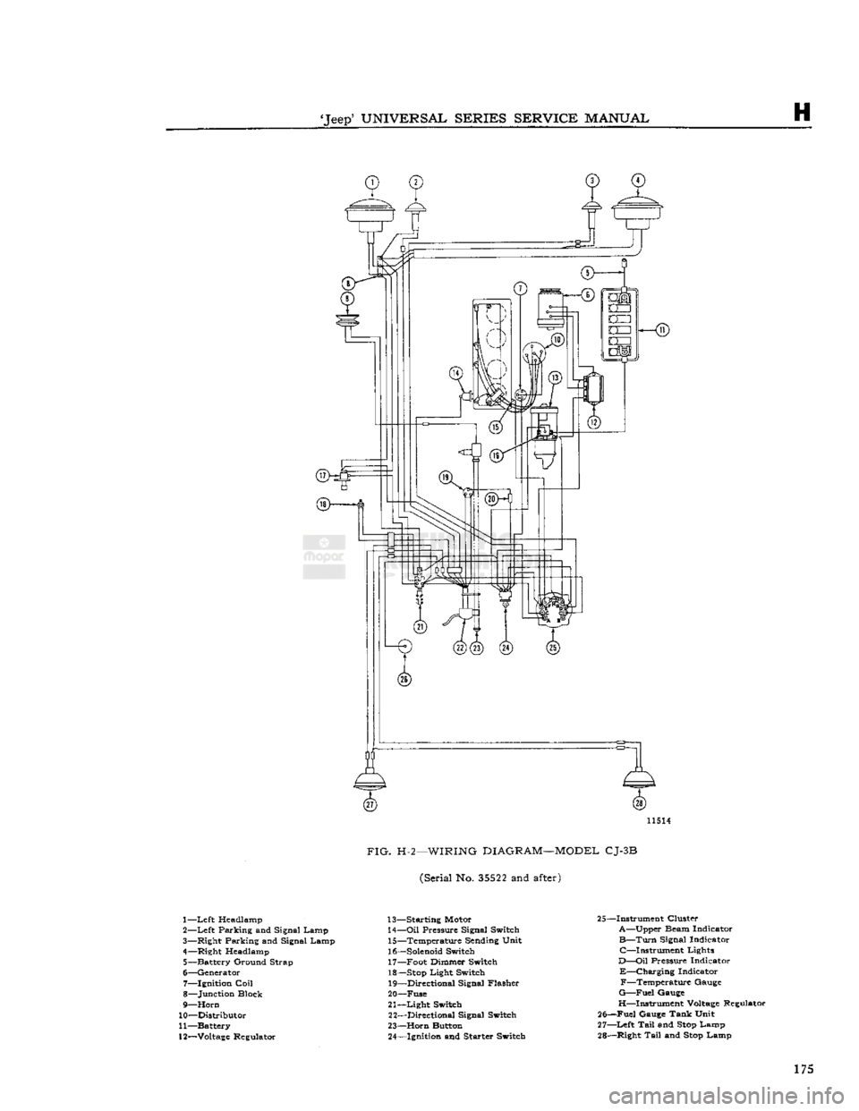
FIG.
H-2—WIRING
DIAGRAM—MODEL
CJ-3B
(Serial No.
35522
and
after)
1—
Left
Headlamp
2—
Left
Parking and Signal Lamp
3— Right Parking and Signal Lamp
4— Right Headlamp 5— Battery Ground Strap
6— Generator 7— Ignition
Coil
8— Junction Block
9—
Horn
10— Distributor
11— Battery
12—
Voltage
Regulator 13— Starting Motor
14—
Oil
Pressure Signal Switch 15— Temperature Sending Unit
16—
Solenoid
Switch 17— Foot Dimmer Switch
18—
Stop
Light Switch 19— Directional Signal Flasher
20— Fuse
21—
Light
Switch 22— Directional Signal Switch
23—
Horn
Button 24— Ignition and Starter Switch 25—Instrument Cluster
A—Upper Beam Indicator
B—Turn
Signal Indicator C—Instrument Lights
D—Oil
Pressure Indicator
E—Charging
Indicator F—Temperature Gauge
G—Fuel
Gauge
H—Instrument
Voltage
Regulator
25—Fuel Gauge Tank Unit
27—
Left
Tail
and
Stop
Lamp
28— Right
Tail
and
Stop
Lamp 175
Page 176 of 376
H
ELECTRICAL
SYSTEM
11474
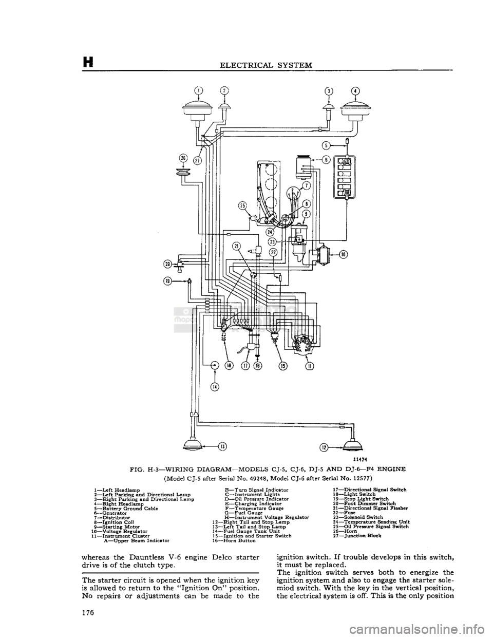
FIG.
H-3—WIRING
DIAGRAM—MODELS
CJ-5, CJ-6, DJ-5 AND DJ-6—F4
ENGINE
(Model CJ-5 after Serial No.
49248,
Model CJ-6 after Serial No.
12577)
1—
Left
Headlamp
B—Turn
Signal Indicator 17—Directional Signal Switch
2—
Left
Parking and Directional Lamp C—Instrument Lights 18—Light Switch
3— Right Parking and Directional Lamp
D—Oil
Pressure Indicator
19—Stop
Light Switch
4— Right Headlamp E—Charging Indicator 20—Foot Dimmer Switch
5— Battery Ground Cable F—Temperature Gauge 21—Directional Signal Flasher
6— Generator
G—Fuel
Gauge 22—Fuse 7— Distributor H—Instrument Voltage Regulator
23—Solenoid
Switch
8— Ignition
Coil
12—Right
Tail
and
Stop
Lamp 24—Temperature Sending Unit
9— Starting Motor 13—Left
Tail
and
Stop
Lamp 25—Oil Pressure Signal Switch
10— Voltage Regulator 14—Fuel Gauge
Tank
Unit 26—Horn
11— Instrument Cluster 15—Ignition and Starter Switch 27—Junction Block
A—Upper
Beam Indicator 16—Horn Button
whereas the Dauntless V-6
engine
Delco starter
ignition
switch. If trouble
develops
in this switch, drive is of the clutch
type.
it must be replaced.
The
ignition
switch
serves
both
to
energize
the
The
starter circuit is
opened
when the
ignition
key
ignition
system
and
also
to
engage
the starter
sole-
is allowed to return to the "Ignition On"
position.
miod switch. With the key in the vertical
position,
No repairs or adjustments can be
made
to the the electrical
system
is off. This is the
only
position
176
Page 177 of 376
'Jeep*
UNIVERSAL
SERIES
SERVICE
MANUAL
H
12968
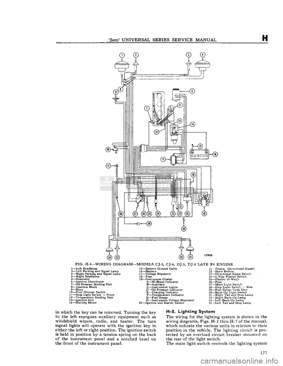
FIG.
H-4—WIRING
DIAGRAM—MODELS
CJ-5, CJ-6, DJ-5, DJ-6
LATE
F4
ENGINE
1—
Left
Headlamp
2—
Left
Parking and Signal Lamp
3— Right Parking and Signal Lamp 4— Right Headlamp
5— Generator
6— Ignition Distributor
7—
Oil
Pressure Sending Unit
8— Junction Block
9—
Horn
10— Foot Dimmer Switch 11—
Stop
Light Switch — Front
12— Temperature Sending Unit
13— Ignition
Coil
14— Starting Motor 15— Battery Ground Cable
16— Battery
17— Voltage Regulator 18—
Fuse
19— Instrument Cluster
A—Hi-Beam
Indicator
B—Auxiliary
C—Instrument
Lights
D—Oil
Pressure Indicator
E—Charging
Indicator
F—Temperature
Indicator
G—Fuel
Gauge
H—Instrument Voltage Regulator
20— Ignition and Starter Switch 21—
Flashei
(Directional Signal)
22—
Horn
Button 23— Directional Signal Switch
24— 4-Way Flasher Switch
25—
Flasher
(4-Way)
26—
Fuse
27—
Main
Light Switch 28—
Stop
Light Switch — Rear
29—
Fuel
Gauge
Tank
Unit
30—
Back-Up
Light Switch
31— Right
Tail
and
Stop
Lamp
32— Right Back-Up Lamp
33—
Left
Back-Up Lamp
34—
Left
Tail
and
Stop
Lamp
in
which the key can be removed. Turning the key
to the
left
energizes
auxiliary
equipment
such as
windshield wipers, radio, and heater. The turn
signal
lights
will
operate
with the
ignition
key in
either the
left
or right
position.
The
ignition
switch is held in
position
by a
tension
spring on the back
of the instrument panel and a
notched
bezel on
the front of the instrument panel.
H-8.
Lighting System
The
wiring for the lighting
system
is shown in the
wiring diagrams, Figs. H-2 thru H-7 of the manual,
which indicate the various units in relation to their
position
in the vehicle. The lighting circuit is pro
tected
by an overload circuit breaker
mounted
on the rear of the light switch.
The
main light switch controls the lighting
system
177
Page 180 of 376
H
ELECTRICAL
SYSTEM
ffKHs)
3—<§)
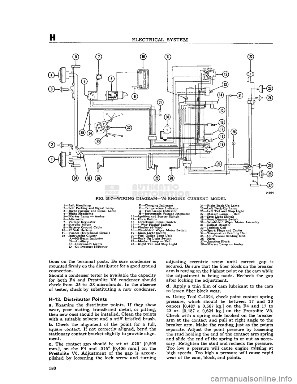
FIG.
H-7—WIRING
DIAGRAM—V6
ENGINE
CURRENT
MODEL
1—
Left
Headlamp
2—Left Parking and Signal Lamp
3— Right Parking and Signal Lamp
4—Right Headlamp 5—
Marker
Lamp — Amber
6— Alternator 7— Voltage Regulator
8— Starting Motor
9— Battery Ground Cable
10— 12 Volt Battery
11—
Flasher
(Directional Signal)
12— Instrument Cluster
A—Hi-Beam
Indicator
B—Auxiliary
C—Instrument
Lights
D—Oil
Pressure Indicator
E—Charging
Indicator
F—Temperature
Indicator
G—Fuel
Gauge Indicator
H—Instrument Voltage Regulator
13— Ignition and Starter Switch
14—
Horn
Button
15— Directional Signal Switch
16— 4-Way Flasher Switch 17—
Flasher
(4-Way)
18— Windshield Wiper Motor Switch
19—
Main
Light Switch
20—
Fuel
Gauge
Tank
Unit
21—
Back-Up
Light Switch
22—
Marker
Lamp — Red
23— Right
Tail
and
Stop
Light 24— Right Back-Up Lamp
25—
Left
Back-Up Lamp 26—
Left
Tail
and
Stop
Light
27—
Marker
Lamp — Red
28—
Stop
Light Switch
29— Foot Dimmer Switch
30— Windshield Wiper Motor Assembly
31—
Ballast
Resistor 32— Ignition
Coil
33—
Spark
Plugs and Cables 34— Temperature Sending Unit
35—
Oil
Pressure Sending Unit 36—
Horn
37— Junction Block
38—
Marker
Lamp — Amber
lions
on the terminal
posts.
Be sure
condenser
is
mounted
firmly on the distributor for a
good
ground
connection.
Should a
condenser
tester
be available the capacity for
both
F4 and Prestolite V6
condenser
should
check from .25 to .28 microfarads. In the
absence
of
tester,
check by substituting a new
condenser.
H-13. Distributor Points
a. Examine the distributor
points.
If
they
show
wear,
poor
mating, transferred metal, or pitting,
then
new
ones
should be installed. Clean the
points
with a suitable
solvent
and a stiff bristled brush.
b. Check the
alignment
of the
point
for a full,
square
contact.
If not correctly aligned, bend the
stationary
contact
bracket slightly to provide align
ment.
c. The
contact
gap should be set at .020"
[0,508
mm.],
on the F4 and .016"
[0,406
mm.] on the
Prestolite V6. Adjustment of the gap is accom plished by
loosening
the lock screw and turning adjusting eccentric screw until correct gap is
secured. Be sure that the fiber block on the breaker
arm
is resting on the
highest
point
on the cam while the adjustment is
being
made. Recheck the gap
after locking the adjustment.
d. Apply a thin film of cam lubricant to the cam to
lessen
fiber block wear.
e. Using Tool C-4094, check
point
contact
spring
pressure, which should be
between
17 and 20
ounces
[0,487
a
0,567
kg.] on the F4 and 17 to 22 oz.
[0,487
a
0,624
kg.] on the Prestolite V6.
Check
with a spring scale
hooked
on the breaker
arm
at the
contact
and pull at right
angle
to the
breaker arm. Make the reading just as the
points
separate. Adjust the
point
pressure by
loosening
the stud holding the end of the
contact
arm spring
and slide the end of the spring in or out as
neces
sary.
Retighten the stud and recheck the pressure. Too low a- pressure will
cause
engine
missing at
high
speeds.
Too high a pressure will
cause
rapid
wear of the cam, block, and
points.
180
Page 215 of 376
'Jeep*
UNIVERSAL
SERIES
SERVICE
MANUAL
H
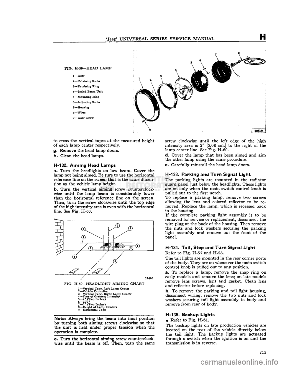
FIG.
H-59—HEAD LAMP
1—
Door
2—
Retaining
Screw
3—
Retaining
Ring
4—
Sealed
Beam
Unit
5—
Mounting
Ring
6—
Adjusting
Screw 7—
Housing
8—
Wires
9—
Door
Screw 310669
to cross the vertical
tapes
at the measured height
of each lamp center respectively.
g.
Remove the head lamp doors.
h.
Clean
the head lamps.
H-132.
Aiming Head Lamps
a.
Turn
the headlights on low beam. Cover the lamp not being aimed. Be sure to use the horizontal reference line on the screen that is the same dimen
sion as the vehicle lamp height.
b.
Turn
the vertical aiming screw counterclock
wise until the lamp beam is considerably lower
than
the horizontal reference line on the screen.
Then,
turn
the screw clockwise until the top
edge
of the high intensity
area
is even with the horizontal
line.
See Fig. H-60.
I
(T)
JT)
1'.'' | '':'
11460
FIG.
H-60—HEADLIGHT AIMING
CHART
1—
Vertical
Tape,
Left
Lamp
Center
2—
Vehicle
Centerline
3—
—Vertical
Tape,
Right
Lamp
Center
4—
Zone
of Greatest Intensity
5—
2
*
(Two Inches)
6— 25'0
'
7—
2
*
(Two Inches)
8—
Height
of
Lamp
Centers
9—
Horizontal
Tape
Note:
Always bring the beam into final position
by turning both aiming screws clockwise so that
the unit is held under proper tension when the operation is complete.
c. Turn
the horizontal aiming screw counterclock
wise until the beam is off.
Then,
turn
the same
screw
clockwise until the
left
edge
of the high
intensity area is 2" [5,08 cm.] to the right of the
lamp center line. See Fig. H-60.
d.
Cover the lamp that has been aimed and aim
the other lamp using the same procedure.
e.
Carefully
reinstall the head lamp doors.
H-133.
Parking
and
Turn Signal Light
The
parking lights are mounted in the radiator
guard
panel just below the headlights. These lights
are
on only when the main switch control knob is
pulled
out to the first notch.
To
replace a parking lamp, remove two screws allowing the lens and colored reflector to be re
moved. Replace the lamp, which is recessed back
in
the housing.
If
the
complete
parking light assembly is to be
removed for service or replacement, disconnect the
wire
plug at the back of the housing.
Then
remove
the nuts and lock washers securing the parking light assembly and remove out the front of the
panel.
H-134. Tail, Stop
and
Turn Signal Light
Refer
to Fig. H-57 and H-58.
The
tail
lights are mounted in the
rear
corner
posts
of the body. They are on whenever the main switch
control
knob is pulled out to any position.
a.
To replace a lamp, remove the snap ring on
early
models
and remove the lens; on late
models
remove lens screws, lens and gasket.
Clean
lens
and
reflector before replacing.
b. To remove the parking and
tail
light housing,
disconnect wiring, remove the two nuts and lock
washers securing
tail
light assembly to body and remove from
rear
of body.
H-135-
Backup Lights •
Refer to Fig. H-61.
The
backup lights on late production vehicles are located on the
rear
of the vehicle directly below
the
tail
light. The backup lights are actuated
through a switch when the ignition is on and the
transmission
is in reverse. 215
Page 217 of 376
'Jeep'
UNIVERSAL
SERIES
SERVICE
MANUAL
H
cuit
lights,
the
signal switch
is
inoperative
and
must
be
replaced.
H-139.
Hazard
Warning Lights
All
current production vehicles
are
equipped with
a
four-way flasher warning system.
The
control switch
is
located
on the
instrument panel left
of
the steering column.
With
the
switch pulled
out,
the
two
front and
two
rear
turn
signal lights flash
on and
off
simultaneously,
as do
both
turn
signal
indicator
lights
on the
instrument clusters.
H-140.
Marker
Lights and Reflector Assembly
The
marker
lights
and
reflector assemblies
on
current
production vehicles
are
mounted
on the
side
of
the front fender and
on the
side
of
the
rear
quarter
panel.
The
spare wheel also mounts
a
marker
light. Some earlier production vehicles have
reflex reflectors mounted on the side of the hood and
on
the
side
of
the
rear
quarter panel. determine
if
dash wiper switch or wiring
is at
fault,
disconnect wiring harness from wiper motor
and
try
operating wiper independently
of
dash switch.
If
still
inoperative
see
procedure under
Par.
H-145.
b. Wiper
will
not
shut
off
— Determine
if
wiper
has both
low
and high speeds, slow speed only,
or
high speed only.
It is
important that
the
wiper
operates
at low
speed during parking cycle.
Dis
connect wiring harness from wiper motor
and try
operating wiper independently
of
dash switch.
If
wiper
shuts
off
correctly with
crank
arm
in
park
position and wiper has both speeds, check
the
lead
between
terminal
and
dash switch ground
and
check
for
defective dash switch.
If
wiper shuts
off
correctly,
but has
high speed only, check lead
be
tween wiper terminal and dash switch
for an
open
circuit
and check
for
defective dash switch.
If
still
inoperative,
see
Par. H-145.
c. Wiper
has
only fast speed.
Check
for
defective dash switch
or
open lead
between
terminal
and
dash switch.
H-141.
Windshield Wiper System
Early
production vehicles equipped with
the
Dauntless V-6
engine
have
two
single speed wind
shield wiper motors mounted above
the
windshield inside
the
vehicle. The wiper motors
are
operated
and
controlled
by a
switch located
on the
instru
ment panel.
Current
production vehicles with stationary wind
shield have
a
two-speed
electric windshield wiper motor mounted below
the
windshield outside
the
vehicle on the driver's side. The wiper motor switch is located
on the
instrument panel
to the
left
of
the steering column.
H-142.
Two-Speed Wiper Motor
The
two-speed
electric wiper motor
is
operated and
controlled
by a
turn
type, three poled, dash switch,
containing
a 6
amp. circuit breaker.
Current
flow
is directed from
the
battery through
the
ignition
switch
to the
wiper dash switch assembly
to the
two-speed
wiper motor, which passes current from the designated motor brush (high,
low or
park)
to
the armature circuit
to
ground.
H-143.
Troubleshooting Procedure
Troubleshooting procedures
are
divided into
two
categories: wiper troubleshooting
in
vehicle; wiper
troubleshooting
on
bench.
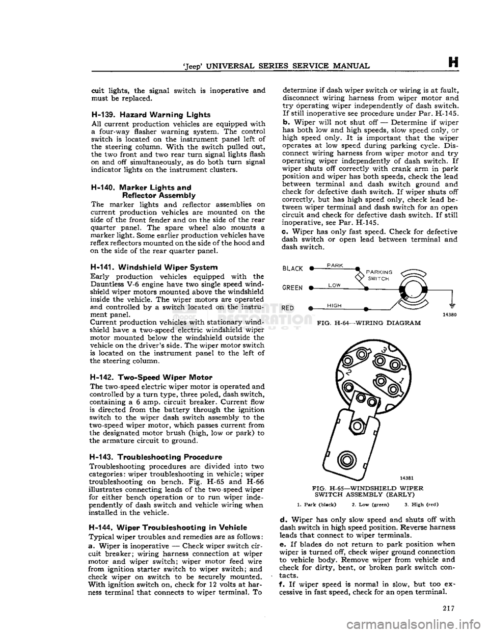
Fig. H-65 and H-66
illustrates connecting leads
of the
two-speed
wiper for either bench operation
or to run
wiper inde
pendently
of
dash switch and vehicle wiring when
installed
in the
vehicle.
H-144. Wiper Troubleshooting
in
Vehicle
Typical
wiper troubles and remedies are
as
follows
:
a.
Wiper
is
inoperative
—
Check
wiper switch
cir
cuit
breaker; wiring harness connection
at
wiper
motor
and
wiper switch; wiper motor
feed
wire
from
ignition starter switch
to
wiper switch;
and
check wiper
on
switch
to be
securely mounted.
With
ignition switch
on,
check
for 12
volts
at
har
ness
terminal that connects
to
wiper terminal.
To
BLACK
PARK
GREEN *-
RED m~
LOW
PARKING
<^^>
SWITCH
V^-O*'
HIGH
FIG.
H-64—WIRING
DIAGRAM
FIG.
H-65—WINDSHIELD
WIPER
SWITCH
ASSEMBLY
(EARLY)
1.
Park
(black)
2. Low (green)
3.
High (red)
d.
Wiper
has
only slow speed
and
shuts
off
with
dash switch in high speed position. Reverse harness
leads that connect
to
wiper terminals.
e. If
blades
do not
return
to
park
position when
wiper
is
turned
off,
check wiper ground connection
to vehicle body. Remove wiper from vehicle
and
check
for
dirty, bent,
or
broken
park
switch con
tacts.
f.
If
wiper speed
is
normal
in
slow,
but too ex
cessive
in
fast speed, check for an open terminal. 217
Page 320 of 376
STEERING
SYSTEM
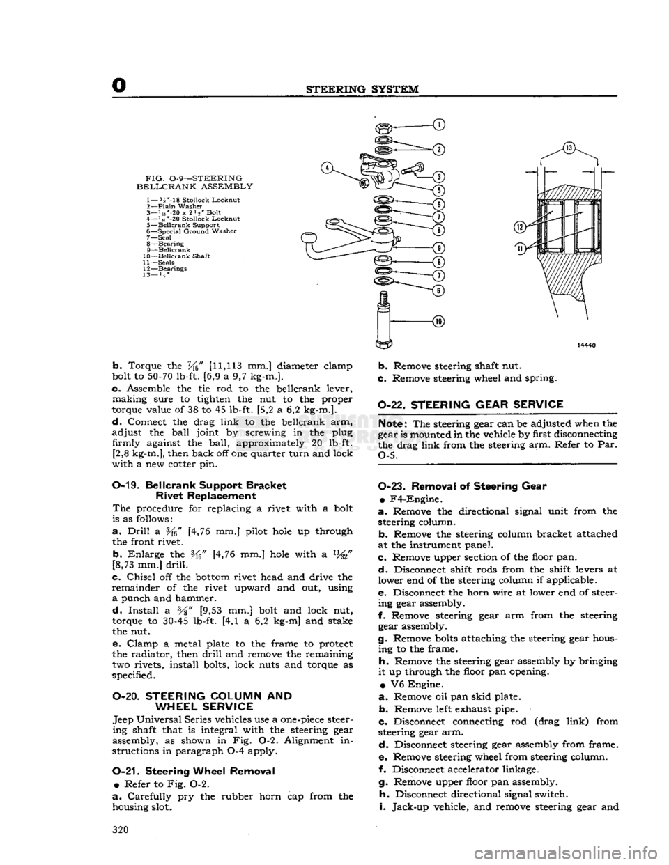
FIG.
0-9—STEERING
BELLCRANK
ASSEMBLY
1— 5s'-18
Stollock
Lockout
2—
Plain
Washer
3— 7 us"-20
x
2 l2' Bolt
4—
71«
*-20
Stollock
Locknut
5—
Beilcrank
Support
6—
Special
Ground
Washer
7— Seal
8—
Bearing
9— Beilcrank
10— Beilcrank
Shaft
11—
Seals
12—
Bearings
13— } s *
b.
Torque the
Vfc"
[11,113
mm.] diameter elamp
bolt to
50-70
lb-ft. [6,9 a 9,7 kg-m.].
c.
Assemble the tie rod to the beilcrank lever,
making
sure to tighten the nut to the proper
torque value of 38 to 45 lb-ft. [5,2 a 6,2 kg-m.].
d.
Connect the drag
link
to the beilcrank arm,
adjust
the
ball
joint by screwing in the plug firmly against the
ball,
approximately 20 lb-ft. [2,8 kg-m.], then back off one quarter
turn
and lock
with
a new cotter pin.
0-19.
Beilcrank
Support
Bracket
Rivet
Replacement
The
procedure for replacing a rivet with a bolt
is as follows:
a.
Drill
a [4,76 mm.] pilot
hole
up through
the front rivet.
b.
Enlarge
the [4,76 mm.]
hole
with a %"
[8,73 mm.]
drill.
c.
Chisel
off the
bottom
rivet head and drive the
remainder
of the rivet upward and out, using
a
punch and hammer.
d.
Install
a %" [9,53 mm.] bolt and lock nut,
torque to
30-45
lb-ft. [4,1 a 6,2 kg-m] and stake
the nut.
e.
Clamp
a metal plate to the frame to protect
the radiator, then
drill
and remove the remaining two rivets, install bolts, lock nuts and torque as
specified.
O-20.
STEERING
COLUMN
AND
WHEEL SERVICE
Jeep
Universal
Series vehicles use a
one-piece
steer
ing
shaft that is integral with the steering gear
assembly, as shown in Fig. 0-2. Alignment in
structions in paragraph 0-4 apply.
0-21.
Steering
Wheel Removal •
Refer to Fig. 0-2.
a.
Carefully
pry the rubber horn cap from the housing slot.
b.
Remove steering shaft nut.
c.
Remove steering wheel and spring.
0-22.
STEERING GEAR SERVICE
Note:
The steering gear can be adjusted when the
gear is mounted in the vehicle by first disconnecting
the drag
link
from the steering arm. Refer to Par.
Q-5.
0-23.
Removal
of
Steering Gear
•
F4-Engine.
a.
Remove the directional signal unit from the steering column.
b.
Remove the steering column bracket attached
at the instrument panel.
c.
Remove upper section of the floor pan.
d.
Disconnect shift rods from the shift levers at
lower end of the steering column if applicable.
e.
Disconnect the horn wire at lower end of steer
ing
gear assembly.
f.
Remove steering gear arm from the steering gear assembly.
g.
Remove
bolts
attaching the steering gear hous
ing
to the frame.
h.
Remove the steering gear assembly by bringing
it
up through the floor pan opening.
•
V6 Engine.
a.
Remove oil pan
skid
plate.
b.
Remove
left
exhaust pipe.
c.
Disconnect connecting rod (drag
link)
from
steering gear arm.
d.
Disconnect steering gear assembly from frame.
e.
Remove steering wheel from steering column.
f. Disconnect accelerator linkage.
g.
Remove upper floor pan assembly.
h.
Disconnect directional signal switch.
i.
Jack-up
vehicle, and remove steering gear and
320
Page 354 of 376
T
BODY
from the windshield wiper vacuum fitting. On
late
models
disconnect electrical wires from wiper
motor. Unlatch the two windshield clamps on each
side
of the windshield.
Fold
the windshield forward
until
the
slot
in the windshield
hinges
aligns with the flat
side
of the pin in the
body
hinges.
Slip wind
shield off the pins and remove from
body.
T-4.
Windshield Glass
The
windshield
glass
is mounted in a rubber
weatherstrip which in turn
mounts
in the frame. A
rubber
locking strip, which
holds
the
glass
firmly in
the frame, is inserted in a moulded
groove
around
the rear
face
of the weatherstrip as shown in Fig.
T-2.
To remove the
glass
it is necessary to first
remove the locking strip which may be pried out
with a screwdriver or similar
tool.
Installation is,
obvious.
T-5.
Canvas Tops
Canvas
tops
are available in
Half
Tops and
Full
Tops.
Installation instructions are provided with
each canvas top kit for each model vehicle.
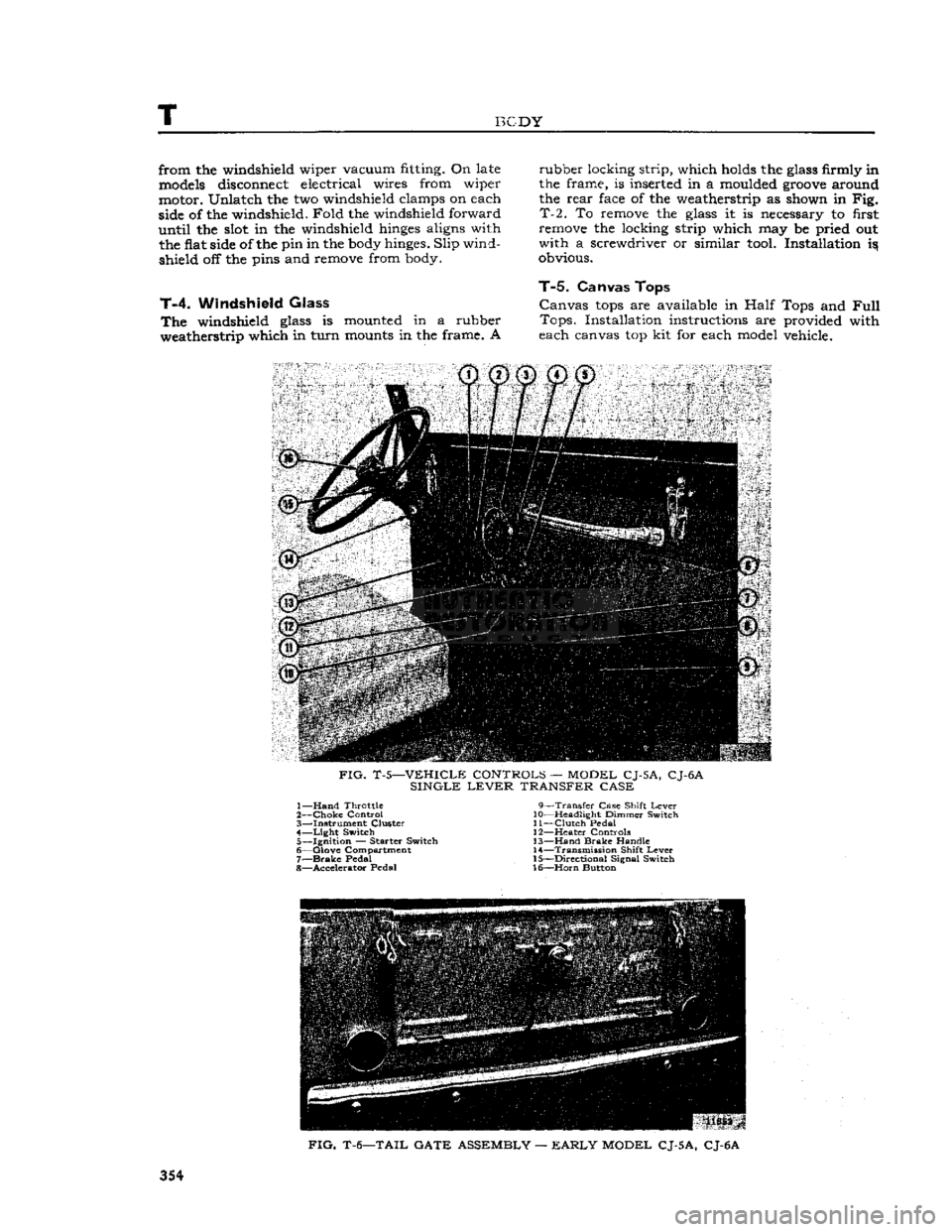
FIG.
T-5—VEHICLE CONTROLS — MODEL CJ-5A, CJ-6A
SINGLE
LEVER
TRANSFER CASE 1—
Hand
Throttle 9—Transfer Case Shift
Lever
2—
Choke
Control 10—Headlight Dimmer Switch
3— Instrument Cluster 11—Clutch Pedal 4—
Light
Switch 12—Heater Controls 5— Ignition — Starter Switch 13—Hand
Brake
Handle
6— Glove Compartment 14—Transmission Shift
Lever
7—
Brake
Pedal 15—Directional Signal Switch
8— Accelerator Pedal 16—Horn Button
FIG.
T-6—TAIL GATE ASSEMBLY —
EARLY
MODEL CJ-5A, CJ-6A
354
Page 355 of 376
'Jeep'
UNIVERSAL
SERIES
SERVICE
MANUAL
T
FIG.
T-7—TAIL
GATE
ASSEMBLY
—
LATE
MODEL
CJ-5, CJ-6
T-6.
Care
of
Fabric
Tops
Remove fabric
tops
from their protective covering
immediately after they are received. Store in a
dry,
clean,
airy
place. If the material is damp, the
top should be installed on the vehicle immediately
and
washed with a mild soap; then
give
the top a
quick
and thorough rinsing.
T-7.
Brake
and
Clutch Pedal Pads
A
clutch and brake pedal pad cover has been re leased which has a .44" [11,18 mm.]
groove
molded into the back side of the pad cover. When installing,
the grooved opening is located down and to the
bottom
of the pedal. See Fig. T-ll. The purpose of the
groove
concerns models not listed in this
manual.
The pedal pad cover formerly used is
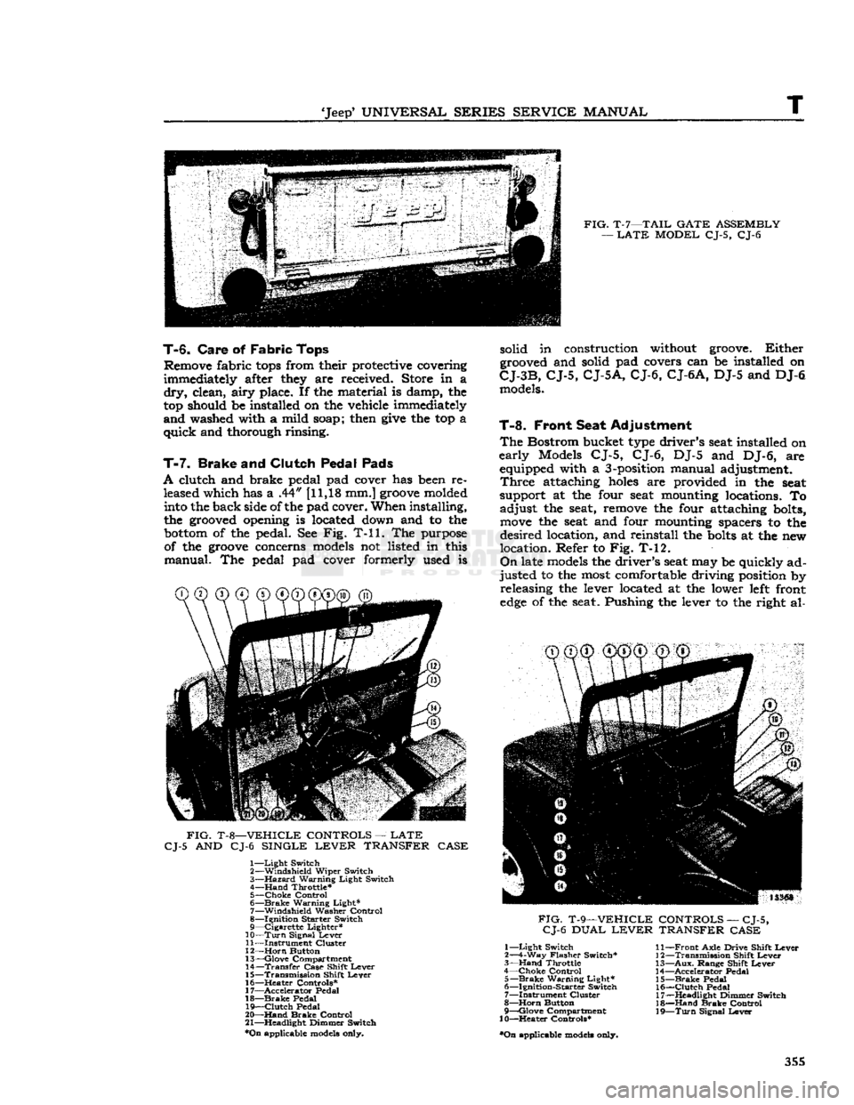
FIG.
T-8—VEHICLE
CONTROLS
—
LATE
CJ-5
AND CJ-6
SINGLE
LEVER
TRANSFER
CASE
1—
Light
Switch
2—
Windshield
Wiper
Switch
3—
Hazard
Warning
Light
Switch
4—
Hand
Throttle*
5—
Choke
Control
6—
Brake
Warning
Light*
7—
Windshield
Washer
Control
8—
Ignition
Starter
Switch
9—
Cigarette
Lighter*
10—
Turn
Signal
Lever
11—
Instrument
Cluster
12—
Horn
Button
13—
Glove
Compartment
14—
Transfer
Case
Shift
Lever
15—
Transmission
Shift
Lever
16—
^Heater
Controls*
17—
Accelerator
Pedal
18—
Brake
Pedal
19—
Clutch
Pedal
20—
Hand
Brake
Control
21—
Headlight
Dimmer
Switch
*On
applicable models only. solid in construction without groove.
Either
grooved and solid pad covers can be installed on
CJ-3B,
CJ-5,
CJ-5A,
CJ-6,
CJ-6A,
DJ-5 and DJ-6 models.
T-8.
Front Seat Adjustment
The
Bostrom bucket type driver's seat installed on
early
Models CJ-5, CJ-6, DJ-5 and DJ-6, are equipped with a 3-position manual adjustment.
Three
attaching
holes
are provided in the seat
support at the four seat mounting locations. To
adjust
the seat, remove the four attaching bolts,
move
the seat and four mounting spacers to the
desired
location, and reinstall the
bolts
at the new
location. Refer to Fig. T-12.
On
late models the driver's seat may be quickly ad
justed
to the most comfortable driving position by releasing the lever located at the lower left front
edge
of the seat. Pushing the lever to the right al-
CD CD®
®@©"®^
FIG.
T-9—VEHICLE
CONTROLS
—
CJ-5,
CJ-6
DUAL
LEVER
TRANSFER
CASE
1—
Light
Switch
2—4-Way
Flasher
Switch*
3—
Hand
Throttle
4—
Choke
Control
5—
Brake
Warning
Light*
6—
Ignition-Starter
Switch
7—
Instrument
Cluster
8—
Horn
Button
9—
Qlove
Compartment
10—Heater
Controls*
•On
applicable models only.
11—
Front
Axle
Drive
Shift
Lever
12—
Transmission
Shift
Lever
13—
Aux.
Range
Shift
Lever
14—
Accelerator
Pedal
15—
Brake
Pedal
16—
Clutch
Pedal
17—
Headlight
Dimmer
Switch
18—
Hand
Brake
Control
19—
Turn
Signal
Lever
355