ECU JEEP COMMANDER 2010 1.G Owner's Manual
[x] Cancel search | Manufacturer: JEEP, Model Year: 2010, Model line: COMMANDER, Model: JEEP COMMANDER 2010 1.GPages: 460, PDF Size: 7.11 MB
Page 163 of 460
6. Airbag Warning LightThis light turns on and remains on for six to
eight seconds as a bulb check when the ignition
switch is first turned ON. If the light is not on
during starting, stays on, or turns on while
driving, have the system inspected by an authorized
dealer as soon as possible.
7. Anti-Lock Brake (ABS) Light This light monitors the Anti-Lock Brake System
(ABS). The light will turn on when the ignition
switch is turned to the ON position and may
stay on for as long as four seconds.
If the ABS light remains on or turns on while driving, it
indicates that the Anti-Lock portion of the brake system
is not functioning and that service is required. However,
the conventional brake system will continue to operate
normally if the BRAKE warning light is not on. If the ABS light is on, the brake system should be serviced
as soon as possible to restore the benefits of Anti-Lock
brakes. If the ABS light does not turn on when the
Ignition switch is turned to the ON position, have the
light inspected by an authorized dealer.
8. Tachometer
Indicates the engine speed in revolutions per minute
(RPM).
9. Vehicle Security Light
This light will flash rapidly for approximately
15 seconds when the vehicle theft alarm is
arming. The light will flash at a slower speed
continuously after the alarm is set. The security
light will also come on for about three seconds when the
ignition is first turned on.
4
UNDERSTANDING YOUR INSTRUMENT PANEL 163
Page 172 of 460
Electronic Vehicle Information Center (EVIC)
Displays
When the appropriate conditions exist, the EVIC displays
the following messages:
•TURN SIGNAL ON
•PERFORM SERVICE
•DAMAGED KEY — KEY DOES NOT COMMUNI-
CATE
•KEY NOT PROGRAMMED — KEY NOT PRO-
GRAMMED
•WRONG KEY — KEY DOES NOT BELONG TO
VEHICLE
•KEY NOT PROGRAMMED — EXCEEDED KEY PRO-
GRAM LIMIT
•PROGRAMMING ACTIVE — NEW KEY PRO-
GRAMMED
•SERVICE SECURITY KEY
•DRIVER/PASSENGER DOOR OPEN (with graphic)
•LEFT/RIGHT REAR DOOR OPEN (with graphic)
•X DOORS OPEN (with graphic)
•LIFTGATE OPEN (with graphic)
•LIFTGATE/DOOR OPEN (with graphic)
•LIFTGATE/DOORS OPEN (with graphic)
•LIFTGLASS OPEN (with graphic)
•HOOD OPEN (with graphic)
•HOOD/DOOR OPEN (with graphic)
•HOOD/DOORS OPEN (with graphic)
•LIFTGATE/HOOD OPEN (with graphic)
•HOOD/GLASS/DOOR OPEN (with graphic)
172 UNDERSTANDING YOUR INSTRUMENT PANEL
Page 322 of 460
Inflation Pressure
This is the cold tire inflation pressure for your vehicle for
all loading conditions up to full GAWR.
Curb Weight
The curb weight of a vehicle is defined as the total weight
of the vehicle with all fluids, including vehicle fuel, at full
capacity conditions, and with no occupants or cargo
loaded into the vehicle. The front and rear curb weight
values are determined by weighing your vehicle on a
commercial scale before any occupants or cargo are
added.
Loading
The actual total weight and the weight of the front and
rear of your vehicle at the ground can best be determined
by weighing it when it is loaded and ready for operation.
The entire vehicle should first be weighed on a commer-
cial scale to ensure that the GVWR has not been ex-
ceeded. The weight on the front and rear of the vehicleshould then be determined separately to be sure that the
load is properly distributed over front and rear axle.
Weighing the vehicle may show that the GAWR of either
the front or rear axles has been exceeded, but the total
load is within the specified GVWR. If so, weight must be
shifted from front to rear, or rear to front, as appropriate
until the specified weight limitations are met. Store the
heavier items down low and be sure that the weight is
distributed equally. Stow all loose items securely before
driving.
Improper weight distributions can have an adverse affect
on the way your vehicle steers and handles, and the way
the brakes operate.
322 STARTING AND OPERATING
Page 330 of 460
NOTE:Remember that everything put into or on the
trailer adds to the load on your vehicle. Also, additional
factory-installed options, or dealer-installed options,
must be considered as part of the total load on your
vehicle. Refer to the Tire and Loading Information plac-
ard in the “Tire—Safety Information” section of this
manual for the maximum combined weight of occupants
and cargo for your vehicle.
Towing Requirements
To promote proper break-in of your new vehicle drive-
train components the following guidelines are recom-
mended:
CAUTION!
•Avoid towing a trailer for the first 500 miles
(805 km) of vehicle operation. Doing so may dam-
age your vehicle.
(Continued)
CAUTION! (Continued)
•During the first 500 miles (805 km) of trailer
towing, limit your speed to 50 mph (80 km/h).
WARNING!
Improper towing can lead to an injury accident.
Follow these guidelines to make your trailer towing
as safe as possible:
Make certain that the load is secured in the trailer
and will not shift during travel. When trailering
cargo that is not fully secured, dynamic load shifts
can occur that may be difficult for the driver to
control. You could lose control of your vehicle and
have an accident.
330 STARTING AND OPERATING
Page 347 of 460
WARNING! (Continued)
•Never start or run the engine with the vehicle on a
jack.
•Do not let anyone sit in the vehicle when it is on a
jack.
•Do not get under the vehicle when it is on a jack.
•Only use the jack in the positions indicated and
for lifting this vehicle during a tire change.
•If working on or near a roadway, be extremely
careful of motor traffic.
•To assure that spare tires, flat or inflated, are
securely stowed, spares must be stowed with the
valve stem facing the ground.
•Turn on the Hazard Warning flasher.1. Remove the spare tire, jack, and tools from storage.
2. Loosen (but do not remove) the wheel lug nuts by
turning them to the left one turn while the wheel is still
on the ground.
3. Assemble the jack and jacking tools as shown. Connect
jack handle driver (1) to two extensions (2), then to the
lug wrench (3).
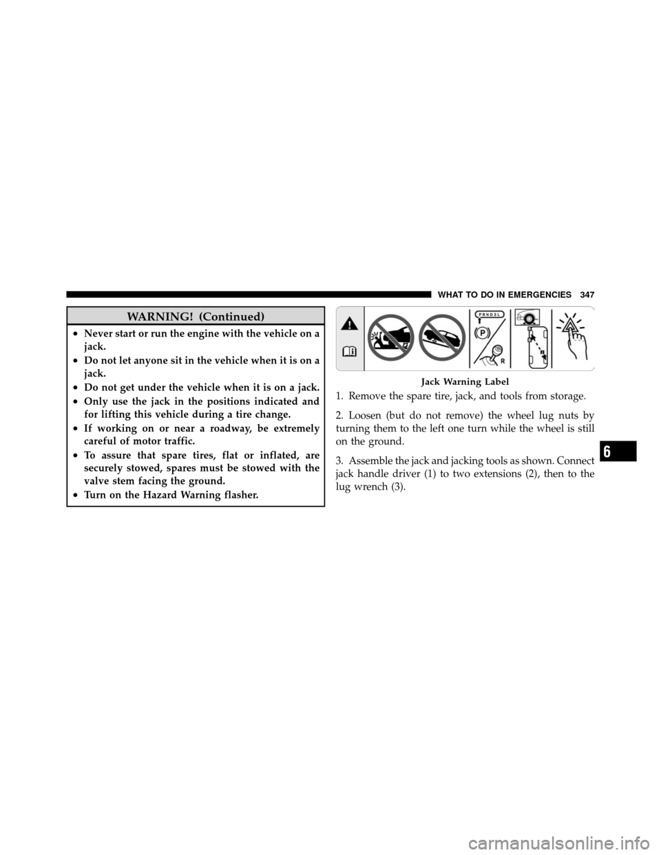
Jack Warning Label
6
WHAT TO DO IN EMERGENCIES 347
Page 350 of 460
9. Finish tightening the lug nuts. Push down on the
wrench while tightening for increased leverage. Alternate
nuts until each nut has been tightened twice. The correct
wheel nut tightness is 95 ft lbs (130 N·m). If in doubt
about the correct tightness, have them checked with a
torque wrench by your authorized dealer or at a service
station.
10. Lower the jack to it’s fully closed position.
WARNING!
A loose tire or jack, thrown forward in a collision or
hard stop could endanger the occupants of the ve-
hicle. Always stow the jack parts and the spare tire in
the places provided.
11. Secure the tire, jack, and tools in their proper loca-
tions. NOTE:
Tire should be stowed with the “beauty” side
up. Storing the tire upside down may result in scratching
or damage to the wheel face. Continue winching up the
tire until you hear the winch “ratchet” three times.
Double check to ensure the tire is snug against the
underbody of the vehicle. Damage to the winch cable
may result if the vehicle is driven with the tire loose.
WARNING!
Do not use power tools to winch the tire up or down.
Impact type tools may damage the winch mechanism.
12. Reinstall the rubber plug into the floor of the cargo
area.
350 WHAT TO DO IN EMERGENCIES
Page 381 of 460
WARNING! (Continued)
•To avoid contamination from foreign matter or
moisture, use only new brake fluid or fluid that
has been in a tightly closed container. Keep the
master cylinder reservoir cap secured at all times.
Brake fluid in a open container absorbs moisture
from the air resulting in a lower boiling point.
This may cause it to boil unexpectedly during hard
or prolonged braking, resulting in sudden brake
failure. This could result in a accident.
•Overfilling the brake fluid reservoir can result in
spilling brake fluid on hot engine parts, causing
the brake fluid to catch fire. Brake fluid can also
damage painted and vinyl surfaces, care should be
taken to avoid its contact with these surfaces.(Continued)
WARNING! (Continued)
•Do not allow petroleum based fluid to contami-
nate the brake fluid. Brake seal components could
be damaged, causing partial or complete brake
failure. This could result in an accident.
Front/Rear Axle Fluid
Front Axle Fluid Level Check
Lubricant should be to the bottom of the oil fill hole.
Rear Axle Fluid Level Check
Lubricant should be 1/2 inch (1 cm) below the oil fill
hole.
Adding Fluid
Add lubricant only at the fill hole and only to the level
specified above.
7
MAINTAINING YOUR VEHICLE 381
Page 404 of 460
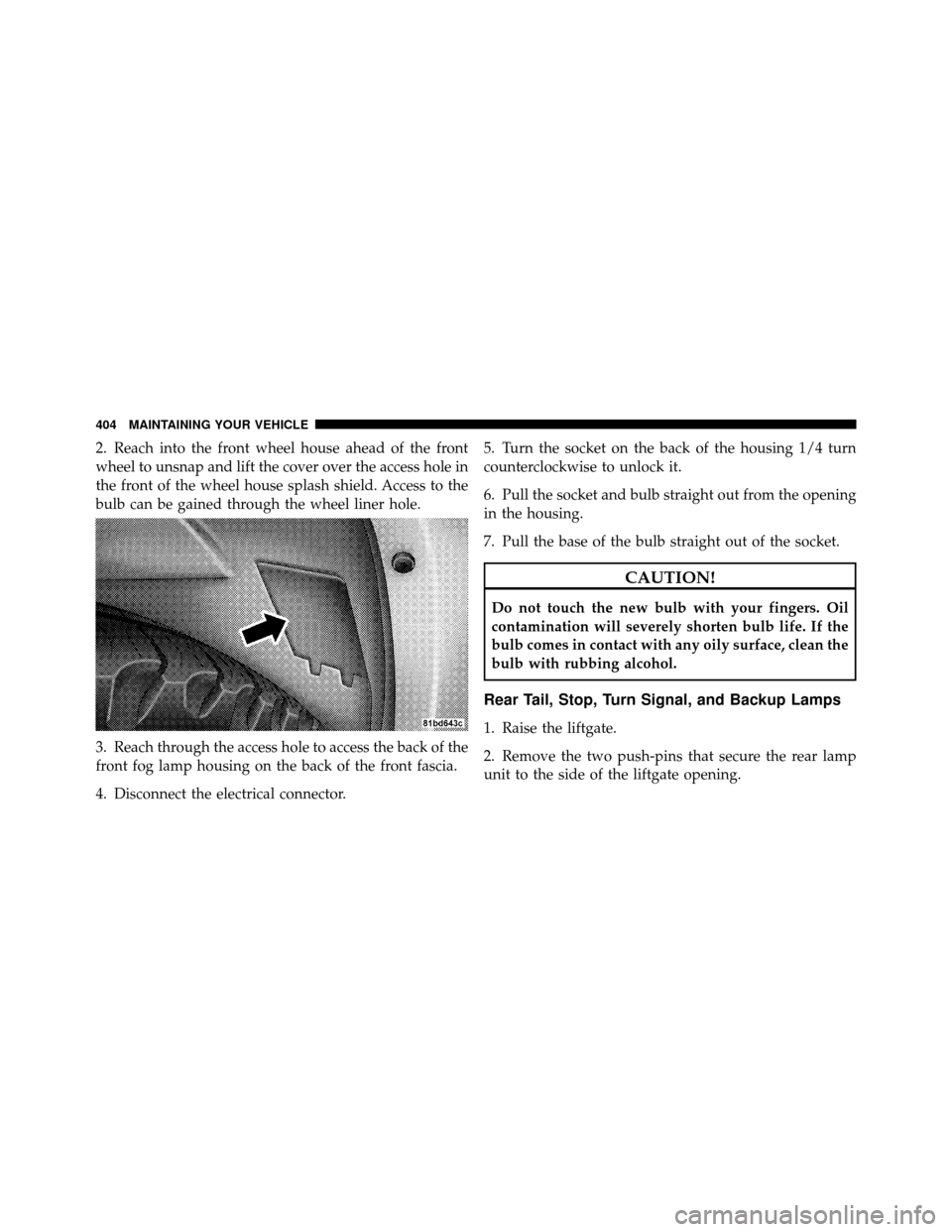
2. Reach into the front wheel house ahead of the front
wheel to unsnap and lift the cover over the access hole in
the front of the wheel house splash shield. Access to the
bulb can be gained through the wheel liner hole.
3. Reach through the access hole to access the back of the
front fog lamp housing on the back of the front fascia.
4. Disconnect the electrical connector.5. Turn the socket on the back of the housing 1/4 turn
counterclockwise to unlock it.
6. Pull the socket and bulb straight out from the opening
in the housing.
7. Pull the base of the bulb straight out of the socket.
CAUTION!
Do not touch the new bulb with your fingers. Oil
contamination will severely shorten bulb life. If the
bulb comes in contact with any oily surface, clean the
bulb with rubbing alcohol.
Rear Tail, Stop, Turn Signal, and Backup Lamps
1. Raise the liftgate.
2. Remove the two push-pins that secure the rear lamp
unit to the side of the liftgate opening.
404 MAINTAINING YOUR VEHICLE
Page 406 of 460
5. Disconnect the electrical connector.
6. Pull the socket and bulb straight out from the opening
in the housing.
7. Pull the base of the bulb straight out of the socket.
CAUTION!
Do not touch the new bulb with your fingers. Oil
contamination will severely shorten bulb life. If the
bulb comes in contact with any oily surface, clean the
bulb with rubbing alcohol.
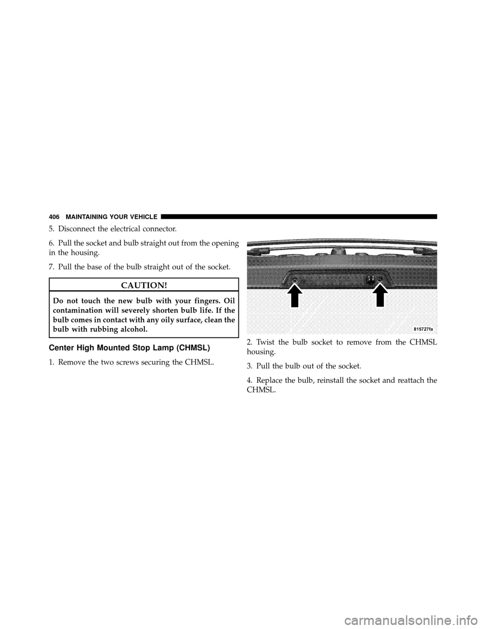
Center High Mounted Stop Lamp (CHMSL)
1. Remove the two screws securing the CHMSL.2. Twist the bulb socket to remove from the CHMSL
housing.
3. Pull the bulb out of the socket.
4. Replace the bulb, reinstall the socket and reattach the
CHMSL.
406 MAINTAINING YOUR VEHICLE
Page 442 of 460
ABS (Anti-Lock Brake System).............. 269
Adding Fuel ........................... 318
Adjustable Pedals ........................ 117
Air Cleaner, Engine (Engine Air Cleaner Filter) . . . 366
Air Conditioner Maintenance ............... 368
Air Conditioning ........................ 226
Air Conditioning, Operating Tips ............ 235
Air Conditioning, Rear Zone ................ 233
Air Conditioning Refrigerant ............... 369
Air Conditioning System .................. 226
Air Filter .............................. 366
Air Pressure, Tires ....................... 295
Airbag .............................. 49,57
Airbag Deployment ....................... 58
Airbag Light ................... 50,56,61,75,163
Airbag Maintenance ....................... 60
Airbag, Side .......................... 55,57
Airbag, Window (Side Curtain) ...........51,55,57
Alarm, Panic ............................ 24 Alarm (Security Alarm)
.................19,163
Alterations/Modifications, Vehicle ............. 9
Antenna, Satellite Radio ................... 216
Antifreeze (Engine Coolant) ................ 407
Anti-Lock Brake System (ABS) ............269,272
Anti-Lock Warning Light .................. 163
Anti-Theft System ....................... 163
Appearance Care ........................ 387
Arming Theft System (Security Alarm) ......... 19
Assist, Hill Start ........................ 280
Auto Down Power Windows ................ 31
Automatic Dimming Mirror ................. 82
Automatic Door Locks ..................... 29
Automatic Headlights .................... 105
Automatic Temperature Control (ATC) ......... 226
Automatic Transmission ................248,383
Adding Fluid ......................... 385
Fluid and Filter Changes ................. 383
Fluid Level Check ................... 384,385
442 INDEX