torque JEEP COMMANDER 2010 1.G User Guide
[x] Cancel search | Manufacturer: JEEP, Model Year: 2010, Model line: COMMANDER, Model: JEEP COMMANDER 2010 1.GPages: 78, PDF Size: 7.31 MB
Page 40 of 78

FOUR-WHEEL DRIVE
OPERATION
Quadra-Trac I®Operating
Instructions/Precautions
• The Quadra-Trac I®is a single-speed
(HI range only) transfer case, which
provides convenient full-time
four–wheel drive. No driver interaction
is required. The Brake Traction Control
(BTC) System, which combines
standard ABS and Traction Control,
provides resistance to any wheel that is
slipping to allow additional torque
transfer to wheels with traction.
Quadra-Trac II®/Quadra-Drive
II®Operating Instructions/
Precautions
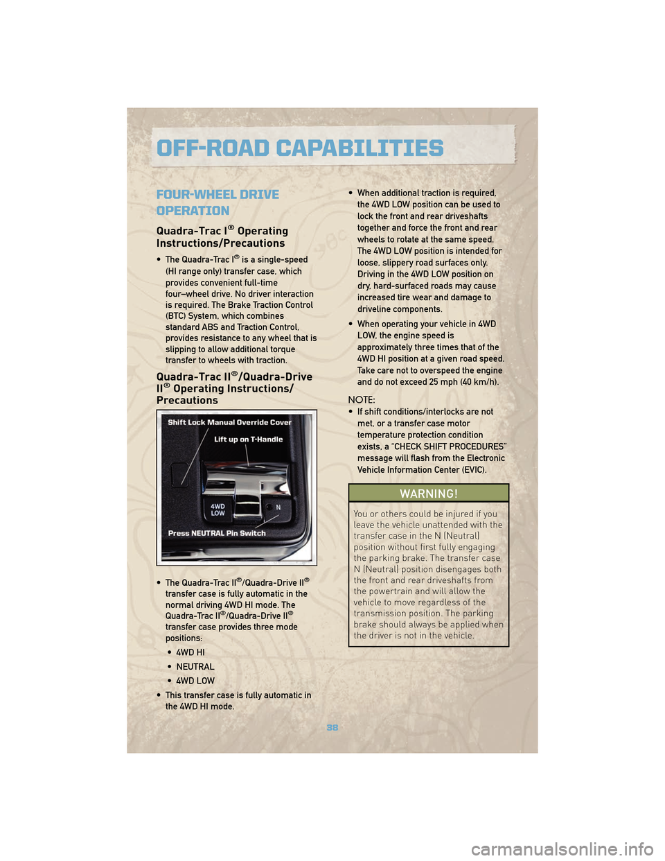
• The Quadra-Trac II®/Quadra-Drive II®
transfer case is fully automatic in the
normal driving 4WD HI mode. The
Quadra-Trac II
®/Quadra-Drive II®
transfer case provides three mode
positions:
• 4WD HI
• NEUTRAL
• 4WD LOW
• This transfer case is fully automatic in the 4WD HI mode. • When additional traction is required,
the 4WD LOW position can be used to
lock the front and rear driveshafts
together and force the front and rear
wheels to rotate at the same speed.
The 4WD LOW position is intended for
loose, slippery road surfaces only.
Driving in the 4WD LOW position on
dry, hard-surfaced roads may cause
increased tire wear and damage to
driveline components.
• When operating your vehicle in 4WD LOW, the engine speed is
approximately three times that of the
4WD HI position at a given road speed.
Take care not to overspeed the engine
and do not exceed 25 mph (40 km/h).
NOTE:
• If shift conditions/interlocks are not met, or a transfer case motor
temperature protection condition
exists, a “CHECK SHIFT PROCEDURES”
message will flash from the Electronic
Vehicle Information Center (EVIC).
WARNING!
You or others could be injured if you
leave the vehicle unattended with the
transfer case in the N (Neutral)
position without first fully engaging
the parking brake. The transfer case
N (Neutral) position disengages both
the front and rear driveshafts from
the powertrain and will allow the
vehicle to move regardless of the
transmission position. The parking
brake should always be applied when
the driver is not in the vehicle.
OFF-ROAD CAPABILITIES
38
Page 44 of 78

RECREATIONAL TOWING
(BEHIND MOTORHOME,
ETC.)
Towing - Two-Wheel Drive
Models
• Recreational towing is allowed ONLY ifthe driveshaft is removed. Towing with
the rear wheels on the ground while
the driveshaft is connected can result
in severe transmission damage.
WARNING!
If the driveshaft is removed, the
vehicle can roll even if the
transmission is in PARK, which could
cause serious injury or death.
• The parking brake must be firmly engaged and the wheels chocked
during driveshaft removal and
installation. The parking brake must
remain engaged unless the vehicle is
securely and properly connected to the
tow vehicle, or the driveshaft is
completely reinstalled. See your
authorized dealer for proper driveshaft
removal and reinstallation procedures,
including flange orientation/alignment,
use of thread-locking compound,
proper bolt torque specifications, etc.
Towing - Quadra-Trac I®
(Single-Speed Transfer Case)
Four-Wheel Drive Models
• Recreational towing is not allowed.This model does not have a NEUTRAL
position in the transfer case.
Towing - Quadra-Trac II®
/Quadra-Drive II®Four-Wheel
Drive Models
• Depress the brake pedal and turn the
ignition switch ON with the engine shut
off.
• Shift the transmission into NEUTRAL.
• Shift the transfer case into NEUTRAL by holding down the NEUTRAL Pin
switch for four seconds until the LED
starts to blink. The LED will stop
blinking and remain on when the shift
is complete.
• Start the engine and shift into DRIVE to ensure there is no vehicle movement.
• Shut the engine off and shift the transmission into PARK.
• Place the ignition switch in the OFF position and remove the key.
• Apply the parking brake, attach the vehicle to the tow vehicle with a tow
bar and release the parking brake.
• Refer to your Owner's Manual on the DVD for further details.
UTILITY
42
Page 52 of 78

• Place the jack:• For front wheels, place it under the front lower control arm.
• For rear wheels, place it under the axle near the wheel to be changed.
• Turn the jack screw clockwise to firmly engage the jack saddle with the lift area of thesill flange.
• Raise the vehicle by turning the jack screw clockwise. Raise the vehicle only until the tire just clears the surface and enough clearance is obtained to install the spare tire.
WARNING!
Raising the vehicle higher than necessary can make the vehicle less stable and
cause an accident. It could slip off the jack and hurt someone near it. Raise the
vehicle only enough to remove the tire.
• Remove the lug nuts, wheel cover (if equipped) and wheel.
• Position the spare wheel/tire on the vehicle and install the lug nuts with the cone-shaped end toward the wheel. Do NOT attempt to install a center cap or wheel cover on the
compact spare. Lightly tighten the lug nuts clockwise. To avoid the risk of forcing the
vehicle off the jack, do not tighten the nuts fully until the vehicle has been lowered.
• Lower the vehicle by turning the jack screw to the left, and remove the jack and wheel blocks.
• Finish tightening the lug nuts. Push down on the wrench while tightening for increased leverage. Alternate nuts until each one has been tightened twice. The correct wheel nut
tightness is 95 ft lbs (130 N•m). If in doubt about the correct tightness, have them
checked with a torque wrench by your authorized dealer or at a service station.
WARNING!
A loose tire or jack, thrown forward in a collision or hard stop, could endanger the
occupants of the vehicle. Always stow the jack parts and the spare tire in the places
provided.
• Secure the tire, jack, and tools in their proper locations.
NOTE: Tire should be stowed with the “beauty” side up. Storing the tire upside down may
result in scratching or damage to the wheel face. Continue winching up the tire until you
hear the winch “ratchet” three times.
WHAT TO DO IN EMERGENCIES
50