wheel JEEP COMMANDER 2010 1.G User Guide
[x] Cancel search | Manufacturer: JEEP, Model Year: 2010, Model line: COMMANDER, Model: JEEP COMMANDER 2010 1.GPages: 78, PDF Size: 7.31 MB
Page 3 of 78
INTRODUCTION/WELCOME
WELCOME FROM
CHRYSLER GROUP LLC.......... 2
CONTROLS AT A GLANCE
DRIVER COCKPIT.............. 4
INSTRUMENT CLUSTER .......... 6
GETTING STARTED
KEYFOB .................. 8
THEFT ALARM............... 9
SEAT BELT ................. 9
FRONT SEATS ...............10
REAR SEATS ................13
TILT/TELESCOPING STEERING
COLUMN ..................15
ADJUSTABLE PEDALS ...........16
PROGRAMMABLE FEATURES .......16
OPERATING YOUR VEHICLE
TURN SIGNAL/LIGHTS LEVER .......17
WIPER/WASHER LEVER ..........18
SPEED CONTROL LEVER .........19
ELECTRONIC RANGE SELECT (ERS) . . . 20
MANUAL CLIMATE CONTROLS ......20
AUTOMATIC TEMPERATURE CONTROLS
(ATC) ....................21
PARKSENSE
®REAR PARK ASSIST ....22
PARKVIEW®REAR BACK-UP CAMERA . . 22
POWER LIFTGATE .............23
LIFTGATE FLIPPER GLASS ........23
POWER SUNROOF .............23
WIND BUFFETING .............24
ELECTRONICS
NON-TOUCH-SCREEN RADIOS ......25
TOUCH-SCREEN RADIOS .........27
REMOTE AUDIO CONTROLS ........31
VIDEO ENTERTAINMENT SYSTEM
(VES)™ ...................31
ELECTRONIC VEHICLE INFORMATION
CENTER (EVIC) ...............33
UNIVERSAL GARAGE DOOR OPENER . . . 33
POWER INVERTER .............34
POWER OUTLET ..............35
uconnect™ phone .............35
VOICE RECOGNITION ............37
OFF-ROAD CAPABILITIES
FOUR-WHEEL DRIVE OPERATION .....38
UTILITY
INTERIOR STORAGE COMPARTMENTS . . 40
TRAILER TOWING WEIGHTS (MAXIMUM
TRAILER WEIGHT RATINGS)........41
RECREATIONAL TOWING (BEHIND
MOTORHOME, ETC.) ............42
BRAKE/TRANSMISSION INTERLOCK
MANUAL OVERRIDE ............43
WHAT TO DO IN EMERGENCIES
24 HOUR TOWING ASSISTANCE ......44
INSTRUMENT CLUSTER WARNING
LIGHTS ...................44
IF YOUR ENGINE OVERHEATS .......47
JACKING AND TIRE CHANGING ......48
JUMP-STARTING ..............51
EMERGENCY TOW HOOKS .........53
TOWING A DISABLED VEHICLE ......54
EVENT DATA RECORDER (EDR) ......55
MAINTAINING YOUR VEHICLE
OPENING THE HOOD............56
ENGINE COMPARTMENT .........57
FLUIDS AND CAPACITIES .........59
MAINTENANCE CHART ..........60
FUSES ...................62
TIRE PRESSURES .............67
WHEEL AND WHEEL TRIM CARE .....68
EXTERIOR BULBS .............68
CONSUMER ASSISTANCE
CHRYSLER GROUP LLC CUSTOMER
CENTER...................69
CHRYSLER CANADA INC. CUSTOMER
CENTER ...................69
ASSISTANCE FOR THE HEARING
IMPAIRED ..................69
PUBLICATIONS ORDERING ........69
REPORTING SAFETY DEFECTS IN
THE 50 UNITED STATES AND
WASHINGTON, D.C. ............70
TIRE WARRANTY ..............70
MOPAR ACCESSORIES
MOPAR®ACCESSORIES..........73
TABLE OF CONTENTS
Page 17 of 78
WARNING!(Continued)
• Do not place anything on the seat that insulates against heat, such as a blanket orcushion. This may cause the seat heater to overheat. Sitting in a seat that has
been overheated could cause serious burns due to the increased surface
temperature of the seat.
CAUTION!
Repeated overheating of the seat could damage the heating element and/or degrade
the material of the seat.
TILT/TELESCOPING STEERING COLUMN
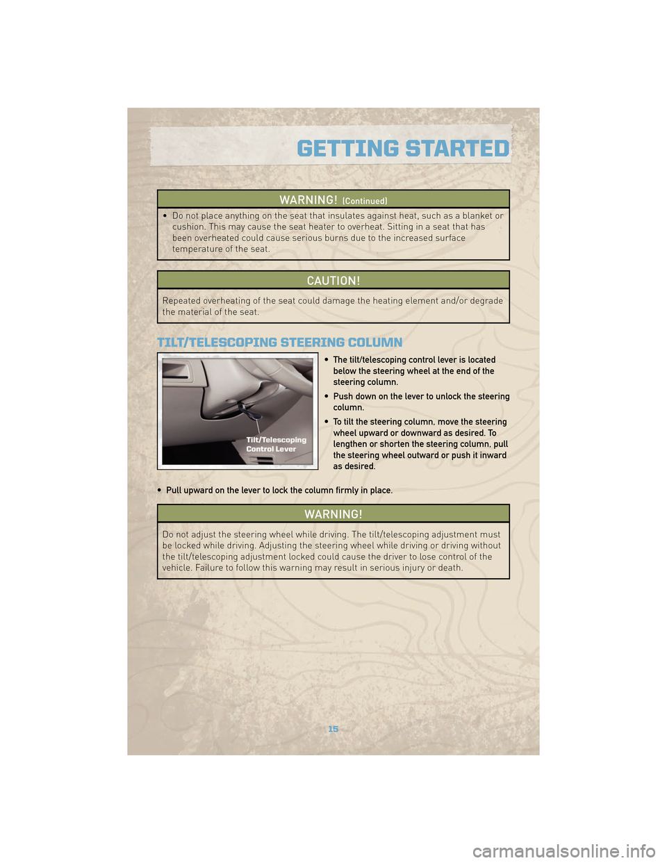
• The tilt/telescoping control lever is locatedbelow the steering wheel at the end of the
steering column.
• Push down on the lever to unlock the steering column.
• To tilt the steering column, move the steering wheel upward or downward as desired. To
lengthen or shorten the steering column, pull
the steering wheel outward or push it inward
as desired.
• Pull upward on the lever to lock the column firmly in place.
WARNING!
Do not adjust the steering wheel while driving. The tilt/telescoping adjustment must
be locked while driving. Adjusting the steering wheel while driving or driving without
the tilt/telescoping adjustment locked could cause the driver to lose control of the
vehicle. Failure to follow this warning may result in serious injury or death.
15
GETTING STARTED
Page 33 of 78
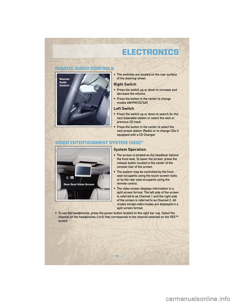
REMOTE AUDIO CONTROLS
• The switches are located on the rear surfaceof the steering wheel.
Right Switch
• Press the switch up or down to increase anddecrease the volume.
• Press the button in the center to change modes AM/FM/CD/SAT.
Left Switch
• Press the switch up or down to search for thenext listenable station or select the next or
previous CD track.
• Press the button in the center to select the next preset station (Radio) or to change CDs if
equipped with a CD Changer.
VIDEO ENTERTAINMENT SYSTEM (VES)™
System Operation
• The screen is located on the headliner behindthe front seat. To lower the screen, press the
release button located in the center of the
console rear of the screen.
• The system may be controlled by the front seat occupants using the touch-screen radio,
or by the rear seat occupants using the
remote control.
• The video screen displays information in a split screen format. The left side of the screen
is referred to as Channel 1 and the right side
of the screen is referred to as Channel 2. All
modes except video modes are displayed in a
split screen format.
• To use the headphones, press the power button located on the right ear cup. Select the channel on the headphones (1or2) that corresponds to the channel selected on the VES™
screen.
31
ELECTRONICS
Page 35 of 78
ELECTRONIC VEHICLE INFORMATION CENTER (EVIC)
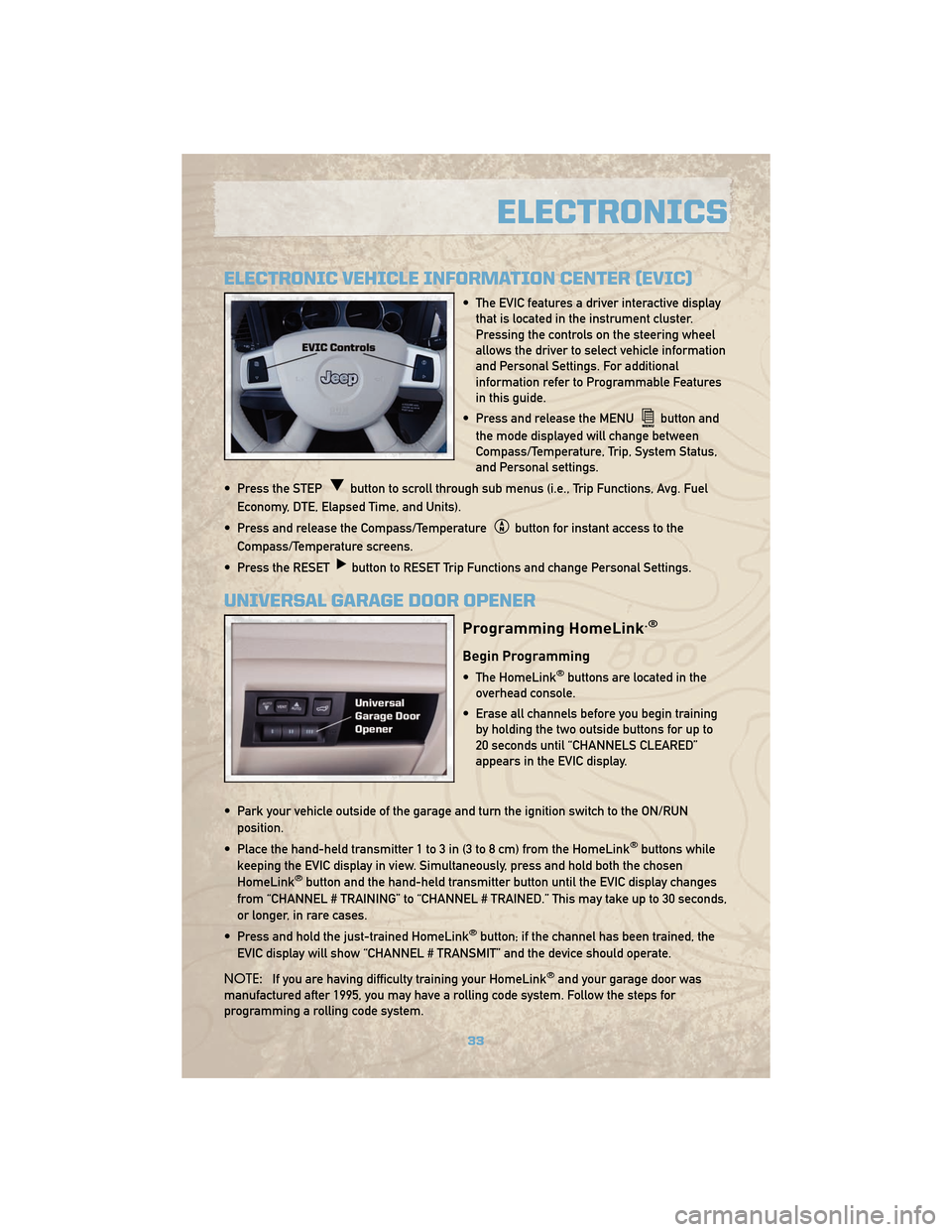
• The EVIC features a driver interactive displaythat is located in the instrument cluster.
Pressing the controls on the steering wheel
allows the driver to select vehicle information
and Personal Settings. For additional
information refer to Programmable Features
in this guide.
• Press and release the MENU
button and
the mode displayed will change between
Compass/Temperature, Trip, System Status,
and Personal settings.
• Press the STEP
button to scroll through sub menus (i.e., Trip Functions, Avg. Fuel
Economy, DTE, Elapsed Time, and Units).
• Press and release the Compass/Temperature
button for instant access to the
Compass/Temperature screens.
• Press the RESET
button to RESET Trip Functions and change Personal Settings.
UNIVERSAL GARAGE DOOR OPENER
Programming HomeLink.®
Begin Programming
• The HomeLink®buttons are located in the
overhead console.
• Erase all channels before you begin training by holding the two outside buttons for up to
20 seconds until “CHANNELS CLEARED”
appears in the EVIC display.
• Park your vehicle outside of the garage and turn the ignition switch to the ON/RUN position.
• Place the hand-held transmitter 1 to 3 in (3 to 8 cm) from the HomeLink
®buttons while
keeping the EVIC display in view. Simultaneously, press and hold both the chosen
HomeLink
®button and the hand-held transmitter button until the EVIC display changes
from “CHANNEL # TRAINING” to “CHANNEL # TRAINED.” This may take up to 30 seconds,
or longer, in rare cases.
• Press and hold the just-trained HomeLink
®button; if the channel has been trained, the
EVIC display will show “CHANNEL # TRANSMIT” and the device should operate.
NOTE: If you are having difficulty training your HomeLink
®and your garage door was
manufactured after 1995, you may have a rolling code system. Follow the steps for
programming a rolling code system.
33
ELECTRONICS
Page 40 of 78
FOUR-WHEEL DRIVE
OPERATION
Quadra-Trac I®Operating
Instructions/Precautions
• The Quadra-Trac I®is a single-speed
(HI range only) transfer case, which
provides convenient full-time
four–wheel drive. No driver interaction
is required. The Brake Traction Control
(BTC) System, which combines
standard ABS and Traction Control,
provides resistance to any wheel that is
slipping to allow additional torque
transfer to wheels with traction.
Quadra-Trac II®/Quadra-Drive
II®Operating Instructions/
Precautions
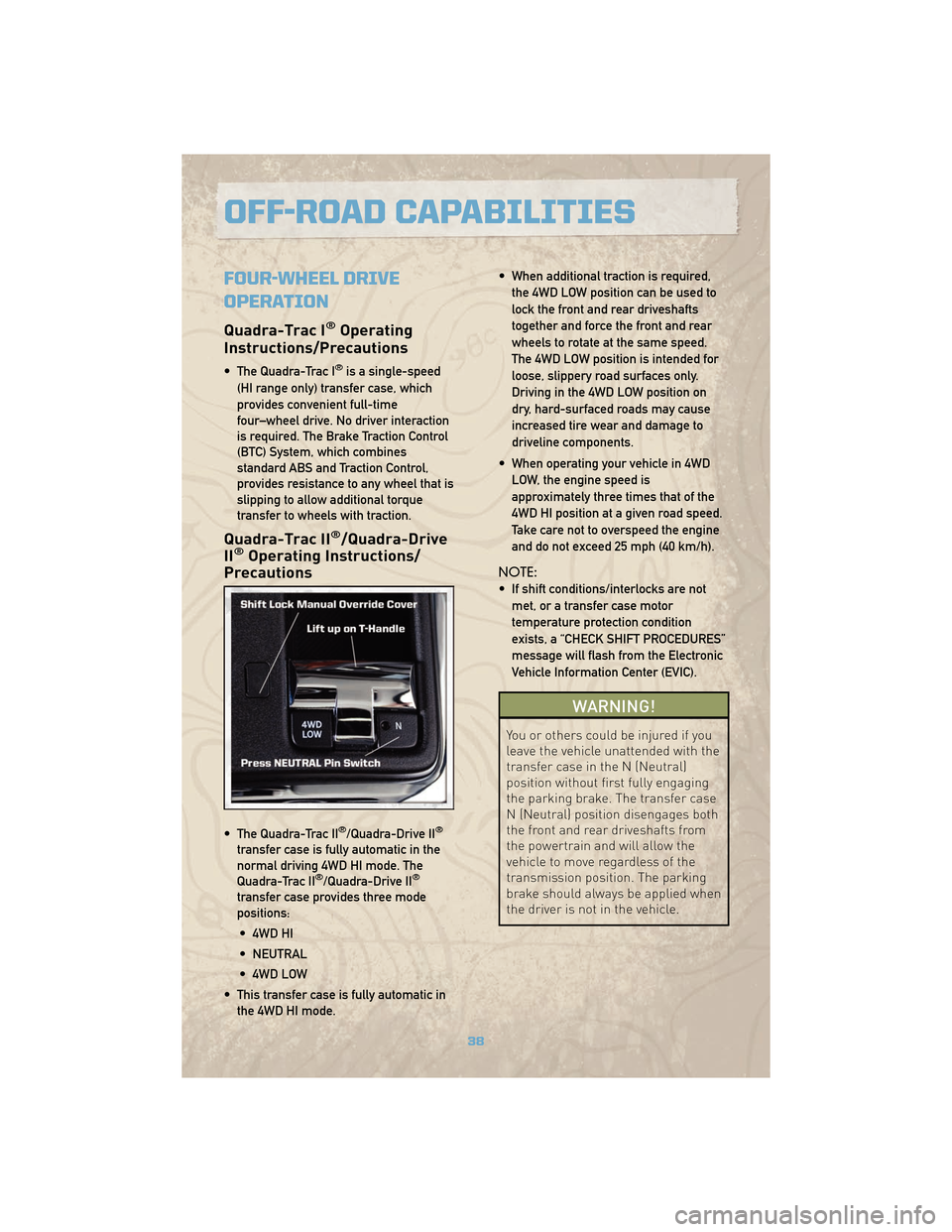
• The Quadra-Trac II®/Quadra-Drive II®
transfer case is fully automatic in the
normal driving 4WD HI mode. The
Quadra-Trac II
®/Quadra-Drive II®
transfer case provides three mode
positions:
• 4WD HI
• NEUTRAL
• 4WD LOW
• This transfer case is fully automatic in the 4WD HI mode. • When additional traction is required,
the 4WD LOW position can be used to
lock the front and rear driveshafts
together and force the front and rear
wheels to rotate at the same speed.
The 4WD LOW position is intended for
loose, slippery road surfaces only.
Driving in the 4WD LOW position on
dry, hard-surfaced roads may cause
increased tire wear and damage to
driveline components.
• When operating your vehicle in 4WD LOW, the engine speed is
approximately three times that of the
4WD HI position at a given road speed.
Take care not to overspeed the engine
and do not exceed 25 mph (40 km/h).
NOTE:
• If shift conditions/interlocks are not met, or a transfer case motor
temperature protection condition
exists, a “CHECK SHIFT PROCEDURES”
message will flash from the Electronic
Vehicle Information Center (EVIC).
WARNING!
You or others could be injured if you
leave the vehicle unattended with the
transfer case in the N (Neutral)
position without first fully engaging
the parking brake. The transfer case
N (Neutral) position disengages both
the front and rear driveshafts from
the powertrain and will allow the
vehicle to move regardless of the
transmission position. The parking
brake should always be applied when
the driver is not in the vehicle.
OFF-ROAD CAPABILITIES
38
Page 44 of 78
RECREATIONAL TOWING
(BEHIND MOTORHOME,
ETC.)
Towing - Two-Wheel Drive
Models
• Recreational towing is allowed ONLY ifthe driveshaft is removed. Towing with
the rear wheels on the ground while
the driveshaft is connected can result
in severe transmission damage.
WARNING!
If the driveshaft is removed, the
vehicle can roll even if the
transmission is in PARK, which could
cause serious injury or death.
• The parking brake must be firmly engaged and the wheels chocked
during driveshaft removal and
installation. The parking brake must
remain engaged unless the vehicle is
securely and properly connected to the
tow vehicle, or the driveshaft is
completely reinstalled. See your
authorized dealer for proper driveshaft
removal and reinstallation procedures,
including flange orientation/alignment,
use of thread-locking compound,
proper bolt torque specifications, etc.
Towing - Quadra-Trac I®
(Single-Speed Transfer Case)
Four-Wheel Drive Models
• Recreational towing is not allowed.This model does not have a NEUTRAL
position in the transfer case.
Towing - Quadra-Trac II®
/Quadra-Drive II®Four-Wheel
Drive Models
• Depress the brake pedal and turn the
ignition switch ON with the engine shut
off.
• Shift the transmission into NEUTRAL.
• Shift the transfer case into NEUTRAL by holding down the NEUTRAL Pin
switch for four seconds until the LED
starts to blink. The LED will stop
blinking and remain on when the shift
is complete.
• Start the engine and shift into DRIVE to ensure there is no vehicle movement.
• Shut the engine off and shift the transmission into PARK.
• Place the ignition switch in the OFF position and remove the key.
• Apply the parking brake, attach the vehicle to the tow vehicle with a tow
bar and release the parking brake.
• Refer to your Owner's Manual on the DVD for further details.
UTILITY
42
Page 50 of 78
JACKING AND TIRE CHANGING
WARNING!
• Do not attempt to change a tire on the side of the vehicle close to moving traffic.Pull far enough off the road to avoid the danger of being hit when operating the
jack or changing the wheel.
• Getting under a jacked-up vehicle is dangerous. The vehicle could slip off the jack and fall on you. You could be crushed. Never get any part of your body under a
vehicle that is on a jack. If you need to get under a raised vehicle, take it to a
service center where it can be raised on a lift.
• The jack is designed to use as a tool for changing tires only. The jack should not be used to lift the vehicle for service purposes. The vehicle should be jacked on a
firm level surface only. Avoid ice or slippery areas.
• If it is necessary to retrieve the spare tire from under the vehicle on the side of the vehicle close to moving traffic, pull far enough off the road to avoid the danger of
being hit.
Jack Location
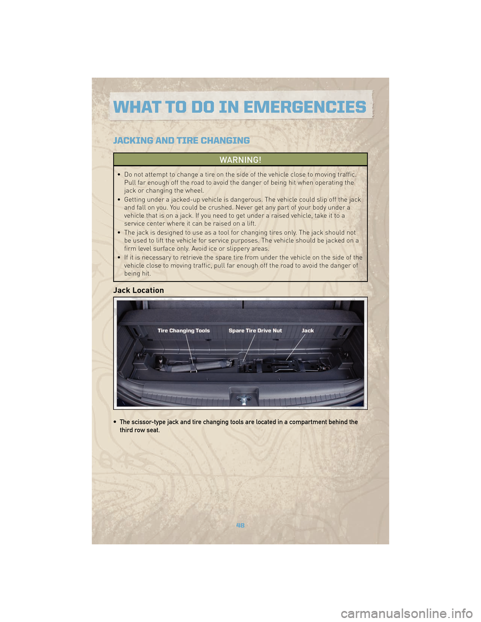
• The scissor-type jack and tire changing tools are located in a compartment behind thethird row seat.
WHAT TO DO IN EMERGENCIES
48
Page 51 of 78
Spare Tire Stowage
• To remove or stow the spare, use the jack handle to rotate the “spare tire drive” nut whichis located under a plastic cover under the cargo load floor, just inside the liftgate opening.
• Lower the spare tire by turning the drive nut counterclockwise with the jack-handle assembly until the spare tire is on the ground with enough cable slack to allow you to
pull the spare tire out from underneath the vehicle.
• When the spare is clear, tilt the retainer at the end of the cable and pull it through the center of the wheel.
Preparations For Jacking
• Park on a firm, level surface. Avoid ice or slippery areas.
• Set the parking brake and shift the automatic transmission into PARK.
• Turn the ignition to LOCK and turn on the Hazard Warning flasher.
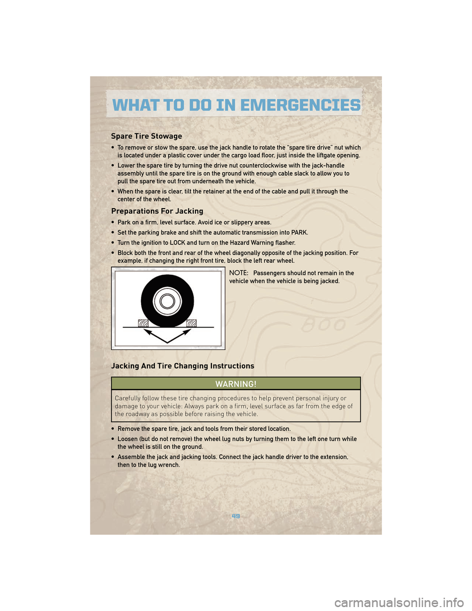
• Block both the front and rear of the wheel diagonally opposite of the jacking position. Forexample, if changing the right front tire, block the left rear wheel.
NOTE:Passengers should not remain in the
vehicle when the vehicle is being jacked.
Jacking And Tire Changing Instructions
WARNING!
Carefully follow these tire changing procedures to help prevent personal injury or
damage to your vehicle: Always park on a firm, level surface as far from the edge of
the roadway as possible before raising the vehicle.
• Remove the spare tire, jack and tools from their stored location.
• Loosen (but do not remove) the wheel lug nuts by turning them to the left one turn while the wheel is still on the ground.
• Assemble the jack and jacking tools. Connect the jack handle driver to the extension, then to the lug wrench.
49
WHAT TO DO IN EMERGENCIES
Page 52 of 78
• Place the jack:• For front wheels, place it under the front lower control arm.
• For rear wheels, place it under the axle near the wheel to be changed.
• Turn the jack screw clockwise to firmly engage the jack saddle with the lift area of thesill flange.
• Raise the vehicle by turning the jack screw clockwise. Raise the vehicle only until the tire just clears the surface and enough clearance is obtained to install the spare tire.
WARNING!
Raising the vehicle higher than necessary can make the vehicle less stable and
cause an accident. It could slip off the jack and hurt someone near it. Raise the
vehicle only enough to remove the tire.
• Remove the lug nuts, wheel cover (if equipped) and wheel.
• Position the spare wheel/tire on the vehicle and install the lug nuts with the cone-shaped end toward the wheel. Do NOT attempt to install a center cap or wheel cover on the
compact spare. Lightly tighten the lug nuts clockwise. To avoid the risk of forcing the
vehicle off the jack, do not tighten the nuts fully until the vehicle has been lowered.
• Lower the vehicle by turning the jack screw to the left, and remove the jack and wheel blocks.
• Finish tightening the lug nuts. Push down on the wrench while tightening for increased leverage. Alternate nuts until each one has been tightened twice. The correct wheel nut
tightness is 95 ft lbs (130 N•m). If in doubt about the correct tightness, have them
checked with a torque wrench by your authorized dealer or at a service station.
WARNING!
A loose tire or jack, thrown forward in a collision or hard stop, could endanger the
occupants of the vehicle. Always stow the jack parts and the spare tire in the places
provided.
• Secure the tire, jack, and tools in their proper locations.
NOTE: Tire should be stowed with the “beauty” side up. Storing the tire upside down may
result in scratching or damage to the wheel face. Continue winching up the tire until you
hear the winch “ratchet” three times.
WHAT TO DO IN EMERGENCIES
50
Page 56 of 78
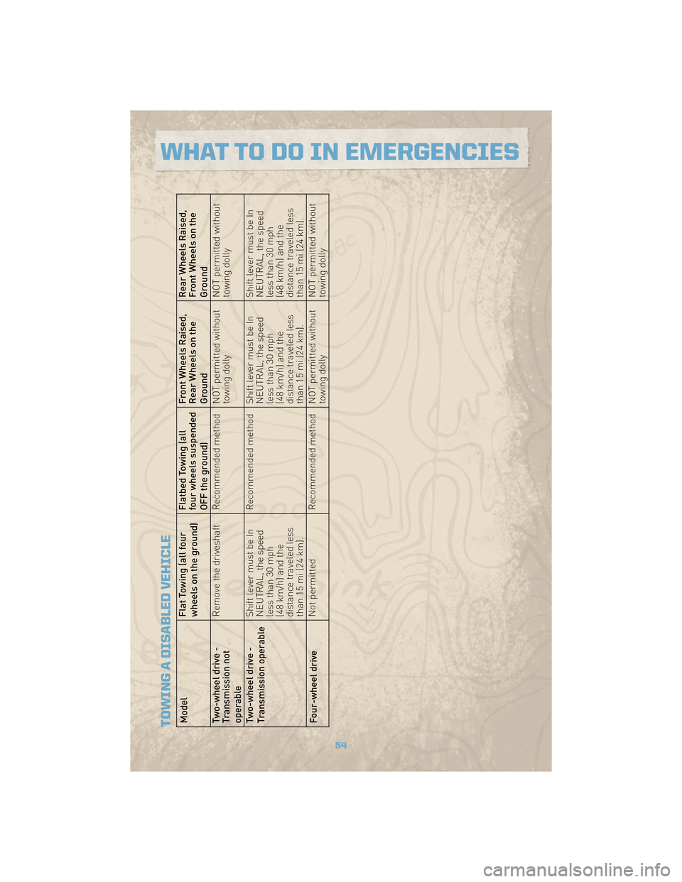
TOWING A DISABLED VEHICLEModelFlat Towing (all four
wheels on the ground)Flatbed Towing (all
four wheels suspended
OFF the ground)Front Wheels Raised,
Rear Wheels on the
GroundRear Wheels Raised,
Front Wheels on the
Ground
Two-wheel drive -
Transmission not
operable Remove the driveshaft Recommended method NOT permitted without
towing dollyNOT permitted without
towing dolly
Two-wheel drive -
Transmission operable Shift lever must be In
NEUTRAL, the speed
less than 30 mph
(48 km/h) and the
distance traveled less
than 15 mi (24 km).Recommended method Shift lever must be In
NEUTRAL, the speed
less than 30 mph
(48 km/h) and the
distance traveled less
than 15 mi (24 km).Shift lever must be In
NEUTRAL, the speed
less than 30 mph
(48 km/h) and the
distance traveled less
than 15 mi (24 km).
Four-wheel drive Not permitted
Recommended method NOT permitted without
towing dollyNOT permitted without
towing dolly
54
WHAT TO DO IN EMERGENCIES