ignition JEEP COMPASS 2015 1.G Owner's Manual
[x] Cancel search | Manufacturer: JEEP, Model Year: 2015, Model line: COMPASS, Model: JEEP COMPASS 2015 1.GPages: 132, PDF Size: 21.94 MB
Page 81 of 132
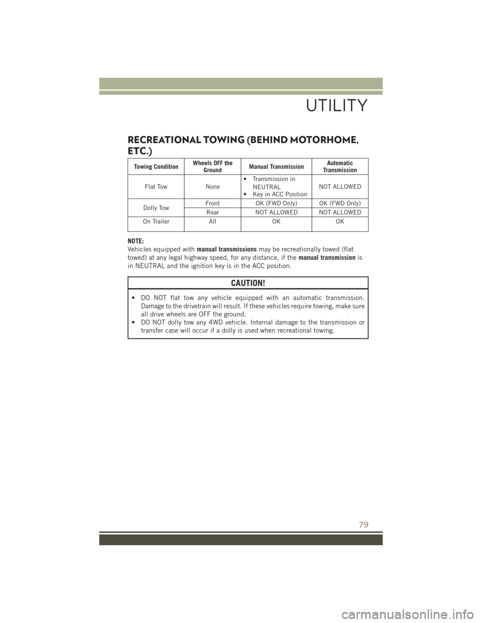
RECREATIONAL TOWING (BEHIND MOTORHOME,
ETC.)
Towing ConditionWheels OFF theGroundManual TransmissionAutomaticTransmission
Flat TowNone• Transmission in
NEUTRAL• Key in ACC PositionNOT ALLOWED
Dolly TowFrontOK (FWD Only) OK (FWD Only)
RearNOT ALLOWED NOT ALLOWED
On TrailerAllOKOK
NOTE:
Vehicles equipped withmanual transmissionsmay be recreationally towed (flat
towed) at any legal highway speed, for any distance, if themanual transmissionis
in NEUTRAL and the ignition key is in the ACC position.
CAUTION!
• DO NOT flat tow any vehicle equipped with an automatic transmission.
Damage to the drivetrain will result. If these vehicles require towing, make sure
all drive wheels are OFF the ground.
• DO NOT dolly tow any 4WD vehicle. Internal damage to the transmission or
transfer case will occur if a dolly is used when recreational towing.
UTILITY
79
Page 83 of 132
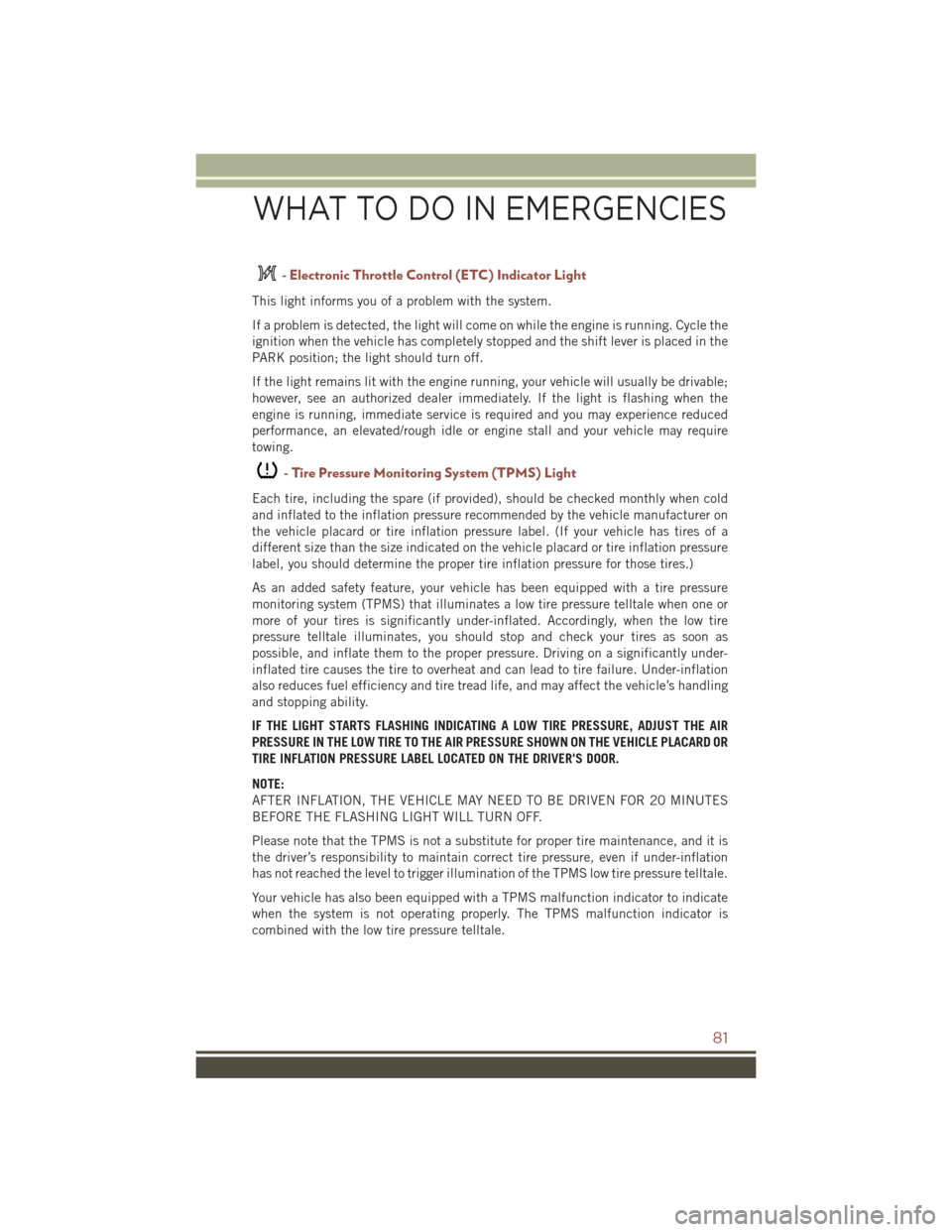
- Electronic Throttle Control (ETC) Indicator Light
This light informs you of a problem with the system.
If a problem is detected, the light will come on while the engine is running. Cycle the
ignition when the vehicle has completely stopped and the shift lever is placed in the
PARK position; the light should turn off.
If the light remains lit with the engine running, your vehicle will usually be drivable;
however, see an authorized dealer immediately. If the light is flashing when the
engine is running, immediate service is required and you may experience reduced
performance, an elevated/rough idle or engine stall and your vehicle may require
towing.
-TirePressureMonitoringSystem(TPMS)Light
Each tire, including the spare (if provided), should be checked monthly when cold
and inflated to the inflation pressure recommended by the vehicle manufacturer on
the vehicle placard or tire inflation pressure label. (If your vehicle has tires of a
different size than the size indicated on the vehicle placard or tire inflation pressure
label, you should determine the proper tire inflation pressure for those tires.)
As an added safety feature, your vehicle has been equipped with a tire pressure
monitoring system (TPMS) that illuminates a low tire pressure telltale when one or
more of your tires is significantly under-inflated. Accordingly, when the low tire
pressure telltale illuminates, you should stop and check your tires as soon as
possible, and inflate them to the proper pressure. Driving on a significantly under-
inflated tire causes the tire to overheat and can lead to tire failure. Under-inflation
also reduces fuel efficiency and tire tread life, and may affect the vehicle’s handling
and stopping ability.
IF THE LIGHT STARTS FLASHING INDICATING A LOW TIRE PRESSURE, ADJUST THE AIR
PRESSURE IN THE LOW TIRE TO THE AIR PRESSURE SHOWN ON THE VEHICLE PLACARD OR
TIRE INFLATION PRESSURE LABEL LOCATED ON THE DRIVER'S DOOR.
NOTE:
AFTER INFLATION, THE VEHICLE MAY NEED TO BE DRIVEN FOR 20 MINUTES
BEFORE THE FLASHING LIGHT WILL TURN OFF.
Please note that the TPMS is not a substitute for proper tire maintenance, and it is
the driver’s responsibility to maintain correct tire pressure, even if under-inflation
has not reached the level to trigger illumination of the TPMS low tire pressure telltale.
Your vehicle has also been equipped with a TPMS malfunction indicator to indicate
when the system is not operating properly. The TPMS malfunction indicator is
combined with the low tire pressure telltale.
WHAT TO DO IN EMERGENCIES
81
Page 85 of 132
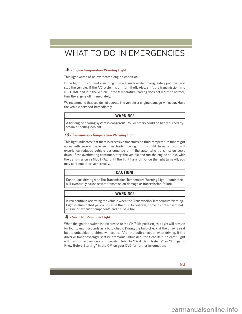
- Engine Temperature Warning Light
This light warns of an overheated engine condition.
If the light turns on and a warning chime sounds while driving, safely pull over and
stop the vehicle. If the A/C system is on, turn it off. Also, shift the transmission into
NEUTRAL and idle the vehicle. If the temperature reading does not return to normal,
turn the engine off immediately.
We recommend that you do not operate the vehicle or engine damage will occur. Have
the vehicle serviced immediately.
WARNING!
A hot engine cooling system is dangerous. You or others could be badly burned by
steam or boiling coolant.
- Transmission Temperature Warning Light
This light indicates that there is excessive transmission fluid temperature that might
occur with severe usage such as trailer towing. If this light turns on, you will
experience reduced vehicle performance until the automatic transmission cools
down. If the overheating continues, stop the vehicle and run the engine at idle, with
the transmission in NEUTRAL, until the light turns off. Once the light turns off, you
may continue to drive normally.
CAUTION!
Continuous driving with the Transmission Temperature Warning Light illuminated
will eventually cause severe transmission damage or transmission failure.
WARNING!
If you continue operating the vehicle when the Transmission Temperature Warning
Light is illuminated you could cause the fluid to boil over, come in contact with hot
engine or exhaust components and cause a fire.
- Seat Belt Reminder Light
When the ignition switch is first turned to the ON/RUN position, this light will turn on
for four to eight seconds as a bulb check. During the bulb check, if the driver's seat
belt is unbuckled, a chime will sound. After the bulb check or when driving, if the
driver or front passenger seat belt remains unbuckled, the Seat Belt Indicator Light
will flash or remain on continuously. Refer to “Seat Belt Systems” in “Things To
Know Before Starting” in the OM on your DVD for further information.
WHAT TO DO IN EMERGENCIES
83
Page 86 of 132
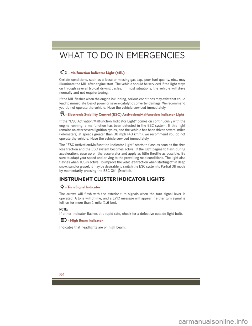
- Malfunction Indicator Light (MIL)
Certain conditions, such as a loose or missing gas cap, poor fuel quality, etc., may
illuminate the MIL after engine start. The vehicle should be serviced if the light stays
on through several typical driving cycles. In most situations, the vehicle will drive
normally and not require towing.
If the MIL flashes when the engine is running, serious conditions may exist that could
lead to immediate loss of power or severe catalytic converter damage. We recommend
you do not operate the vehicle. Have the vehicle serviced immediately.
-ElectronicStabilityControl(ESC)Activation/MalfunctionIndicatorLight
If the “ESC Activation/Malfunction Indicator Light” comes on continuously with the
engine running, a malfunction has been detected in the ESC system. If this light
remains on after several ignition cycles, and the vehicle has been driven several miles
(kilometers) at speeds greater than 30 mph (48 km/h), we recommend you do not
operate the vehicle. Have the vehicle serviced immediately.
The “ESC Activation/Malfunction Indicator Light” starts to flash as soon as the tires
lose traction and the ESC system becomes active. If the light begins to flash during
acceleration, ease up on the accelerator and apply as little throttle as possible. Be
sure to adapt your speed and driving to the prevailing road conditions. The light also
flashes when TCS is active. To improve the vehicle's traction when starting off in deep
snow, sand or gravel, it may be desirable to switch the ESC system to Partial Off mode
by momentarily pressing the ESC Offswitch.
INSTRUMENT CLUSTER INDICATOR LIGHTS
- Turn Signal Indicator
The arrows will flash with the exterior turn signals when the turn signal lever is
operated. A tone will chime, and a EVIC message will appear if either turn signal is
left on for more than 1 mile (1.6 km).
NOTE:
If either indicator flashes at a rapid rate, check for a defective outside light bulb.
- High Beam Indicator
Indicates that headlights are on high beam.
WHAT TO DO IN EMERGENCIES
84
Page 87 of 132
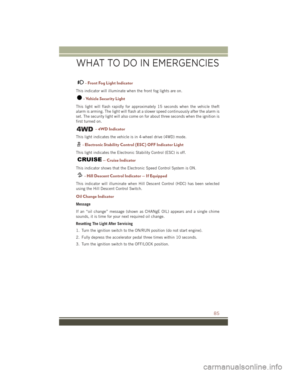
- Front Fog Light Indicator
This indicator will illuminate when the front fog lights are on.
- Vehicle Security Light
This light will flash rapidly for approximately 15 seconds when the vehicle theft
alarm is arming. The light will flash at a slower speed continuously after the alarm is
set. The security light will also come on for about three seconds when the ignition is
first turned on.
– 4WD Indicator
This light indicates the vehicle is in 4-wheel drive (4WD) mode.
- Electronic Stability Control (ESC) OFF Indicator Light
This light indicates the Electronic Stability Control (ESC) is off.
— Cruise Indicator
This indicator shows that the Electronic Speed Control System is ON.
- Hill Descent Control Indicator — If Equipped
This indicator will illuminate when Hill Descent Control (HDC) has been selected
using the Hill Descent Control Switch.
Oil Change Indicator
Message
If an “oil change” message (shown as CHANgE OIL) appears and a single chime
sounds, it is time for your next required oil change.
Resetting The Light After Servicing
1. Turn the ignition switch to the ON/RUN position (do not start engine).
2. Fully depress the accelerator pedal three times within 10 seconds.
3. Turn the ignition switch to the OFF/LOCK position.
WHAT TO DO IN EMERGENCIES
85
Page 90 of 132
Preparations For Jacking
1. Park the vehicle on a firm level surface, avoiding ice or slippery areas.
2. Turn on the Hazard Warning flasher.
3. Set the parking brake.
4. Place the shift lever in PARK (automatic transmission) or REVERSE (manual
transmission).
5. Turn OFF the ignition.
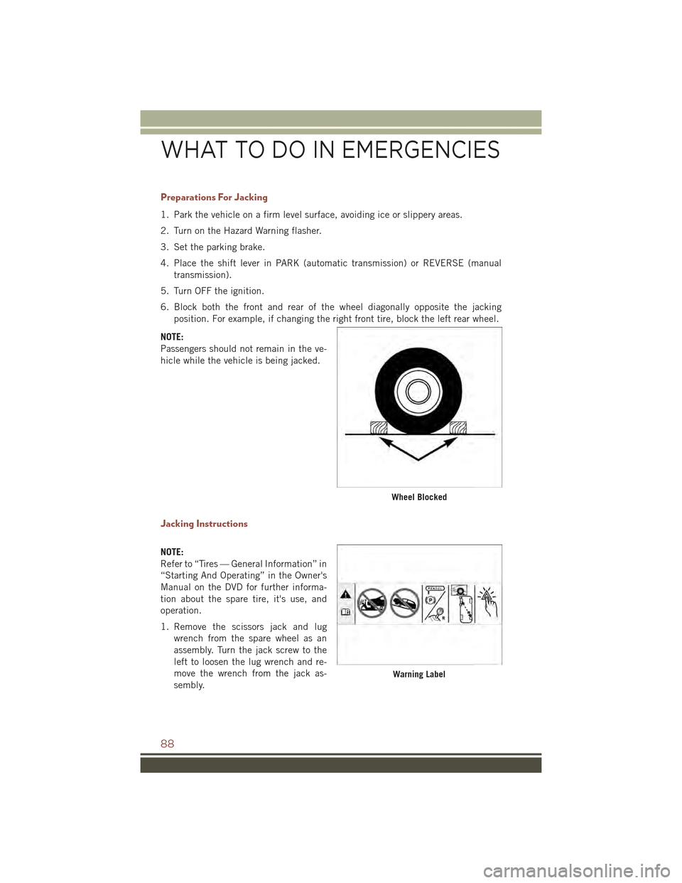
6. Block both the front and rear of the wheel diagonally opposite the jacking
position. For example, if changing the right front tire, block the left rear wheel.
NOTE:
Passengers should not remain in the ve-
hicle while the vehicle is being jacked.
Jacking Instructions
NOTE:
Refer to “Tires — General Information” in
“Starting And Operating” in the Owner's
Manual on the DVD for further informa-
tion about the spare tire, it's use, and
operation.
1. Remove the scissors jack and lug
wrench from the spare wheel as an
assembly. Turn the jack screw to the
left to loosen the lug wrench and re-
move the wrench from the jack as-
sembly.
Wheel Blocked
Warning Label
WHAT TO DO IN EMERGENCIES
88
Page 97 of 132
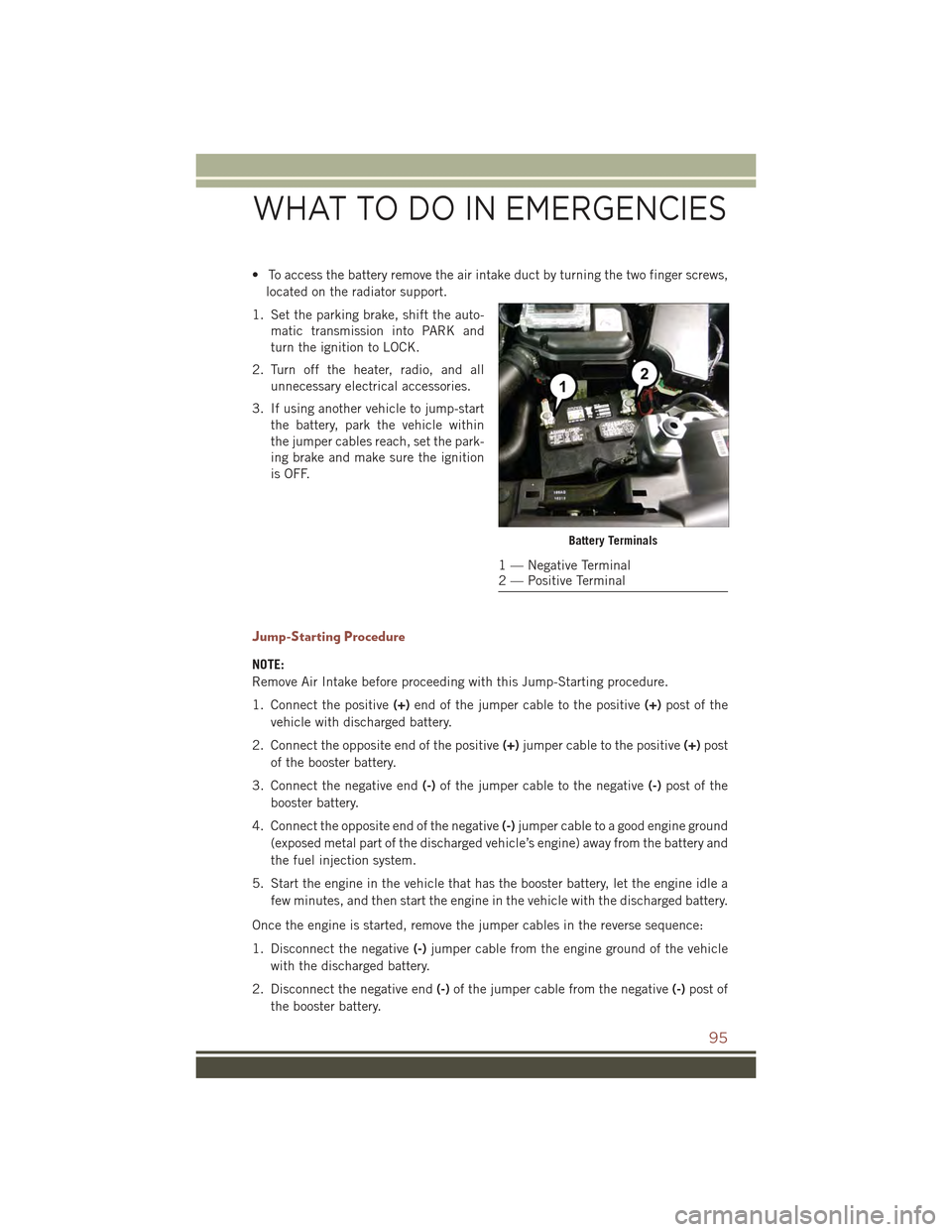
• To access the battery remove the air intake duct by turning the two finger screws,
located on the radiator support.
1. Set the parking brake, shift the auto-
matic transmission into PARK and
turn the ignition to LOCK.
2. Turn off the heater, radio, and all
unnecessary electrical accessories.
3. If using another vehicle to jump-start
the battery, park the vehicle within
the jumper cables reach, set the park-
ing brake and make sure the ignition
is OFF.
Jump-Starting Procedure
NOTE:
Remove Air Intake before proceeding with this Jump-Starting procedure.
1. Connect the positive(+)end of the jumper cable to the positive(+)post of the
vehicle with discharged battery.
2. Connect the opposite end of the positive(+)jumper cable to the positive(+)post
of the booster battery.
3. Connect the negative end(-)of the jumper cable to the negative(-)post of the
booster battery.
4. Connect the opposite end of the negative(-)jumper cable to a good engine ground
(exposed metal part of the discharged vehicle’s engine) away from the battery and
the fuel injection system.
5. Start the engine in the vehicle that has the booster battery, let the engine idle a
few minutes, and then start the engine in the vehicle with the discharged battery.
Once the engine is started, remove the jumper cables in the reverse sequence:
1. Disconnect the negative(-)jumper cable from the engine ground of the vehicle
with the discharged battery.
2. Disconnect the negative end(-)of the jumper cable from the negative(-)post of
the booster battery.
Battery Terminals
1 — Negative Terminal2 — Positive Terminal
WHAT TO DO IN EMERGENCIES
95
Page 98 of 132
3. Disconnect the opposite end of the positive(+)jumper cable from the positive(+)
post of the booster battery.
4. Disconnect the positive(+)end of the jumper cable from the positive(+)post of
the vehicle with discharged battery.
5. Reinstall the air intake duct.
If frequent jump-starting is required to start your vehicle you should have the battery
and charging system inspected at your authorized dealer.
CAUTION!
• Accessories that can be plugged into the vehicle power outlets draw power from
the vehicle’s battery, even when not in use (i.e., cellular phones, etc.).
Eventually, if plugged in long enough, the vehicle’s battery will discharge
sufficiently to degrade battery life and/or prevent the engine from starting.
• Do not use a portable battery booster pack or any other booster source with a
system voltage greater than 12 Volts or damage to the battery, starter motor,
alternator or electrical system may occur.
• Failure to follow these procedures could result in damage to the charging
system of the booster vehicle or the discharged vehicle.
WARNING!
• Do not attempt jump-starting if the battery is frozen. It could rupture or explode
and cause personal injury.
•Take care to avoid the radiator cooling fan whenever the hood is raised. It can start
anytime the ignition switch is on. You can be injured by moving fan blades.
• Remove any metal jewelry such as watch bands or bracelets that might make
an inadvertent electrical contact. You could be seriously injured.
• Batteries contain sulfuric acid that can burn your skin or eyes and generate
hydrogen gas which is flammable and explosive. Keep open flames or sparks
away from the battery.
• Do not allow vehicles to touch each other as this could establish a ground
connection and personal injury could result.
• Failure to follow this procedure could result in personal injury or property
damage due to battery explosion.
•Do not connect the cable to the negative post(-)of the discharged battery. The
resulting electrical spark could cause the battery to explode and could result in
personal injury.
WHAT TO DO IN EMERGENCIES
96
Page 99 of 132
SHIFT LEVER OVERRIDE
If a malfunction occurs and the shift lever cannot be moved out of the PARK position,
you can use the following procedure to temporarily move the shift lever:
1. To access the shift lever override, locate and remove the removable plug in the
right side of the shift lever housing.
2. Firmly set the parking brake.
3. Turn the ignition switch to the ACC or ON position without starting the engine.
4. Press and maintain firm pressure on the brake pedal.
5. Using a screwdriver or similar tool, press and hold the override tab through the
access port on the center console.
6. Move the shift lever into the NEUTRAL position.
7. The vehicle may then be started in NEUTRAL.
8. Reinstall the override cover.
WHAT TO DO IN EMERGENCIES
97
Page 115 of 132
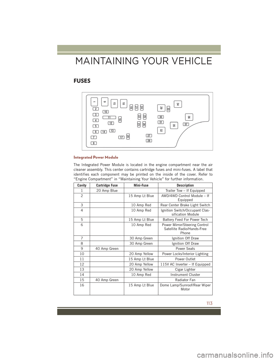
FUSES
Integrated Power Module
The Integrated Power Module is located in the engine compartment near the air
cleaner assembly. This center contains cartridge fuses and mini-fuses. A label that
identifies each component may be printed on the inside of the cover. Refer to
“Engine Compartment” in “Maintaining Your Vehicle” for further information.
Cavity Cartridge Fuse Mini-FuseDescription
120AmpBlueTr a i l e r To w – I f E q u i p p e d
215 Amp Lt Blue AWD/4WD Control Module – IfEquipped
310 Amp Red Rear Center Brake Light Switch
410 Amp Red Ignition Switch/Occupant Clas-sification Module
515 Amp Lt Blue Battery Feed For Power Tech
610 Amp Red Power Mirror/Steering ControlSatellite Radio/Hands-FreePhone
730 Amp GreenIgnition Off Draw
830 Amp GreenIgnition Off Draw
940AmpGreenPower Seats
1020 Amp Yellow Power Locks/Interior Lighting
1115 Amp Lt BluePower Outlet
1220 Amp Yellow 115V AC Inverter – If Equipped
1320 Amp YellowCigar Lighter
1410 Amp RedInstrument Cluster
15 40 Amp GreenRadiator Fan
1615 Amp Lt Blue Dome Lamp/Sunroof/Rear WiperMotor
MAINTAINING YOUR VEHICLE
113