instrument panel JEEP COMPASS 2015 1.G User Guide
[x] Cancel search | Manufacturer: JEEP, Model Year: 2015, Model line: COMPASS, Model: JEEP COMPASS 2015 1.GPages: 132, PDF Size: 21.94 MB
Page 14 of 132
WARNING!
• Do not start or run an engine in a closed garage or confined area. Exhaust gas
contains Carbon Monoxide (CO) which is odorless and colorless. Carbon
Monoxide is poisonous and can cause serious injury or death when inhaled.
• Keep Key Fob transmitters away from children. Operation of the Remote Start
System, windows, door locks or other controls could cause serious injury or
death.
VEHICLE SECURITY ALARM
This Vehicle Security Alarm monitors the doors, liftgate, and ignition switch for
unauthorized operation.
When the alarm is activated, the interior switches for door locks are disabled. The
Vehicle Security Alarm provides both audio and visual signals repeatedly for three
minutes. If the disturbance is still present (driver's door, passenger door, other doors,
ignition) after three minutes, the parking lights and tail lights will flash for an
additional 15 minutes.
To A r m :
• Lock the door using either the power door lock switch (one door must be open) or
the LOCK button on the Remote Keyless Entry (RKE) transmitter (doors can be
open or closed), and close all doors.
The Vehicle Security Light in the instrument cluster will flash for 16 seconds. This
shows that the Vehicle Security Alarm is arming. During this period, if a door is
opened, the ignition is cycled to ON/RUN, or the power door locks are unlocked in any
manner, the Vehicle Security Alarm will automatically disarm.
NOTE:
• The Vehicle Security Alarm will not arm if you lock the doors with the manual door
lock plungers.
• Once armed, the Vehicle Security Alarm disables the unlock switch on the driver
door trim panel and passenger door trim panel.
To D i s a r m T h e S y s t e m :
• Push the Key Fob UNLOCK button or cycle the ignition to the ON/RUN position.
The Vehicle Security Alarm is designed to protect your vehicle; however, you can
create conditions where the Vehicle Security Alarm will give you a false alarm. If one
of the previously described arming sequences has occurred, the Vehicle Security
Alarm will arm regardless of whether you are in the vehicle or not. If you remain in the
vehicle and open a door, the alarm will sound. If this occurs, disarm the Vehicle
Security Alarm.
GETTING STARTED
12
Page 16 of 132
SUPPLEMENTAL RESTRAINT SYSTEM (SRS) — AIR
BAGS
Air Bag System Components
Your vehicle may be equipped with the following air bag system components:
• Occupant Restraint Controller (ORC)
• Air Bag Warning Light
• Steering Wheel and Column
• Instrument Panel
• Knee Impact Bolsters
• Advanced Front Air Bags
• Supplemental Side Air Bags
• Front and Side Impact Sensors
• Seat Belt Pretenioners
• Seat Belt Buckle Switch
• Seat Track Position Sensors
Supplemental Side Air Bags
• This vehicle is equipped with Supplemental Seat-Mounted Side Air Bags (SABs)
located in the outboard side of the front seats. The SABs are marked with a SRS
AIRBAG label sewn into the outboard side of the seats.
• This vehicle is equipped with Supplemental Side Air Bag Inflatable Curtains
(SABICs) located above the side windows. The trim covering the SABICs is labeled
SRS AIRBAG. The SABICs may help reduce the risk of partial or complete ejection
of vehicle occupants through side windows in certain side impact events.
• The SABICs and SABs (“Side Air Bags”) are designed to activate in certain side
impacts and certain rollover events. The Occupant Restraint Controller (“ORC”)
determines whether the deployment of the Side Air Bags in a particular side
impact or rollover event is appropriate, based on the severity and type of collision.
Vehicle damage by itself is not a good indicator of whether or not Side Air Bags
should have deployed.
GETTING STARTED
14
Page 25 of 132
HEATED SEATS
Front Heated Seats
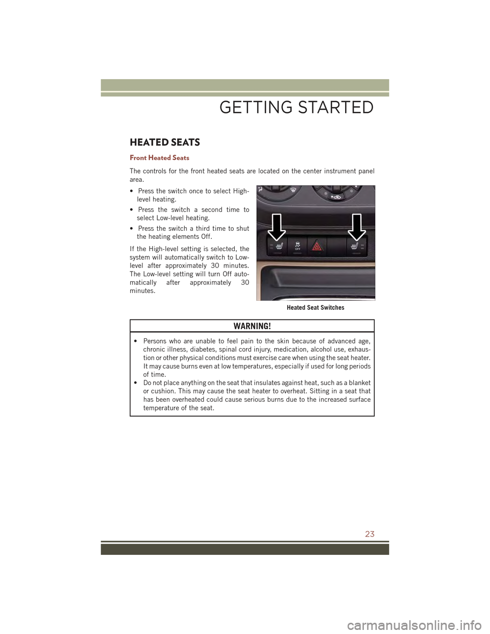
The controls for the front heated seats are located on the center instrument panel
area.
• Press the switch once to select High-
level heating.
• Press the switch a second time to
select Low-level heating.
• Press the switch a third time to shut
the heating elements Off.
If the High-level setting is selected, the
system will automatically switch to Low-
level after approximately 30 minutes.
The Low-level setting will turn Off auto-
matically after approximately 30
minutes.
WARNING!
• Persons who are unable to feel pain to the skin because of advanced age,
chronic illness, diabetes, spinal cord injury, medication, alcohol use, exhaus-
tion or other physical conditions must exercise care when using the seat heater.
It may cause burns even at low temperatures, especially if used for long periods
of time.
• Do not place anything on the seat that insulates against heat, such as a blanket
or cushion. This may cause the seat heater to overheat. Sitting in a seat that
has been overheated could cause serious burns due to the increased surface
temperature of the seat.
Heated Seat Switches
GETTING STARTED
23
Page 28 of 132
TURN SIGNAL/LIGHTS LEVER
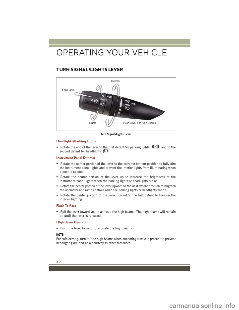
Headlights/Parking Lights
• Rotate the end of the lever to the first detent for parking lightsand to the
second detent for headlights.
Instrument Panel Dimmer
• Rotate the center portion of the lever to the extreme bottom position to fully dim
the instrument panel lights and prevent the interior lights from illuminating when
a door is opened.
• Rotate the center portion of the lever up to increase the brightness of the
instrument panel lights when the parking lights or headlights are on.
•Rotate the center portion of the lever upward to the next detent position to brighten
the odometer and radio controls when the parking lights or headlights are on.
• Rotate the center portion of the lever upward to the last detent to turn on the
interior lighting.
Flash To Pass
• Pull the lever toward you to activate the high beams. The high beams will remain
on until the lever is released.
High Beam Operation
• Push the lever forward to activate the high beams.
NOTE:
For safe driving, turn off the high beams when oncoming traffic is present to prevent
headlight glare and as a courtesy to other motorists.
Turn Signal/Lights Lever
OPERATING YOUR VEHICLE
26
Page 32 of 132
Resume
• To resume a previously selected set speed in memory, push the RES + button and
release.
Cancel
• Push the CANCEL button, or apply the brakes to cancel the set speed and
maintain the set speed memory.
• Push the ON/OFF button to turn the system off and erase the set speed memory.
WARNING!
• Leaving the Electronic Speed Control system on when not in use is dangerous.
You could accidentally set the system or cause it to go faster than you want. You
could lose control and have a collision. Always leave the Electronic Speed
Control system off when you are not using it.
• Electronic Speed Control can be dangerous where the system cannot maintain
a constant speed. Your vehicle could go too fast for the conditions, and you
could lose control. A collision could be the result. Do not use Electronic Speed
Control in heavy traffic or on roads that are winding, icy, snow-covered or
slippery.
PARKVIEW® REAR BACK-UP CAMERA
You can see an on-screen image of the rear of your vehicle whenever the shift lever is
put into REVERSE. The ParkView®Rear Back-Up Camera image will be displayed on
the radio display screen, located on the center stack of the instrument panel.
If the radio display screen appears foggy, clean the camera lens located on the
liftgate.
Refer to your Owner's Manual on the DVD for further details.
WARNING!
Drivers must be careful when backing up; even when using the ParkView®Rear
Back-Up Camera. Always check carefully behind your vehicle, and be sure to
check for pedestrians, animals, other vehicles, obstructions, or blind spots before
backing up. You must continue to pay attention while backing up. Failure to do so
can result in serious injury or death.
OPERATING YOUR VEHICLE
30
Page 77 of 132
POWER OUTLET
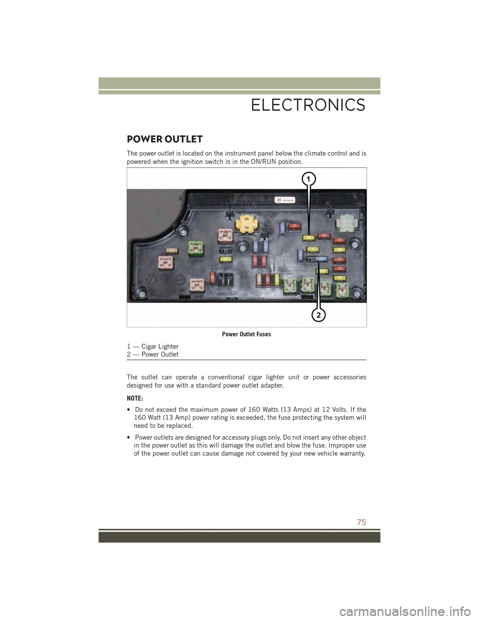
The power outlet is located on the instrument panel below the climate control and is
powered when the ignition switch is in the ON/RUN position.
The outlet can operate a conventional cigar lighter unit or power accessories
designed for use with a standard power outlet adapter.
NOTE:
• Do not exceed the maximum power of 160 Watts (13 Amps) at 12 Volts. If the
160 Watt (13 Amp) power rating is exceeded, the fuse protecting the system will
need to be replaced.
• Power outlets are designed for accessory plugs only. Do not insert any other object
in the power outlet as this will damage the outlet and blow the fuse. Improper use
of the power outlet can cause damage not covered by your new vehicle warranty.
Power Outlet Fuses
1 — Cigar Lighter2 — Power Outlet
ELECTRONICS
75
Page 103 of 132
OPENING THE HOOD
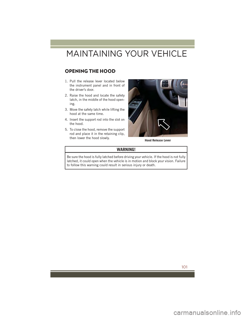
1. Pull the release lever located below
the instrument panel and in front of
the driver’s door.
2. Raise the hood and locate the safety
latch, in the middle of the hood open-
ing.
3. Move the safety latch while lifting the
hood at the same time.
4. Insert the support rod into the slot on
the hood.
5. To close the hood, remove the support
rod and place it in the retaining clip,
then lower the hood slowly.
WARNING!
Be sure the hood is fully latched before driving your vehicle. If the hood is not fully
latched, it could open when the vehicle is in motion and block your vision. Failure
to follow this warning could result in serious injury or death.
Hood Release Lever
MAINTAINING YOUR VEHICLE
101
Page 110 of 132
MAINTENANCE PROCEDURES
For information on the maintenance procedures for your vehicle, please refer to
“Maintenance Procedures” in “Maintaining Your Vehicle” in your Owner’s Manual or
applicable supplement on the DVD for further details.
MAINTENANCE SCHEDULE
Your vehicle is equipped with an automatic oil change indicator system. The oil
change indicator system will remind you that it is time to take your vehicle in for
scheduled maintenance.
Based on engine operation conditions, the oil change indicator message will
illuminate. This means that service is required for your vehicle. Operating conditions
such as frequent short-trips, trailer tow, extremely hot or cold ambient temperatures
will influence when the “Change Oil” or “Oil Change Required” message is dis-
played. Severe Operating Conditions can cause the change oil message to illuminate
as early as 3,500 miles (5,600 km) since last reset. Have your vehicle serviced as
soon as possible, within the next 500 miles (805 km).
On Electronic Vehicle Information Center (EVIC) equipped vehicles, “Oil Change
Required” will be displayed in the EVIC and a single chime will sound, indicating that
an oil change is necessary.
On Non-EVIC equipped vehicles, “Change Oil” will flash in the instrument cluster
odometer and a single chime will sound, indicating that an oil change is necessary.
Your authorized dealer will reset the oil change indicator message after completing
the scheduled oil change. If a scheduled oil change is performed by someone other
than your authorized dealer, the message can be reset by referring to the steps
described under “Instrument Cluster Warning Lights” in “What To Do In Emergen-
cies” in this guide or “Instrument Cluster Descriptions” or “Electronic Vehicle
Information Center (EVIC)” in “Understanding Your Instrument Panel” in the
Owner’s Manual on your DVD for further information.
NOTE:
Under no circumstances should oil change intervals exceed 10,000 miles
(16,000 km) or twelve months, whichever comes first.
MAINTAINING YOUR VEHICLE
108
Page 127 of 132
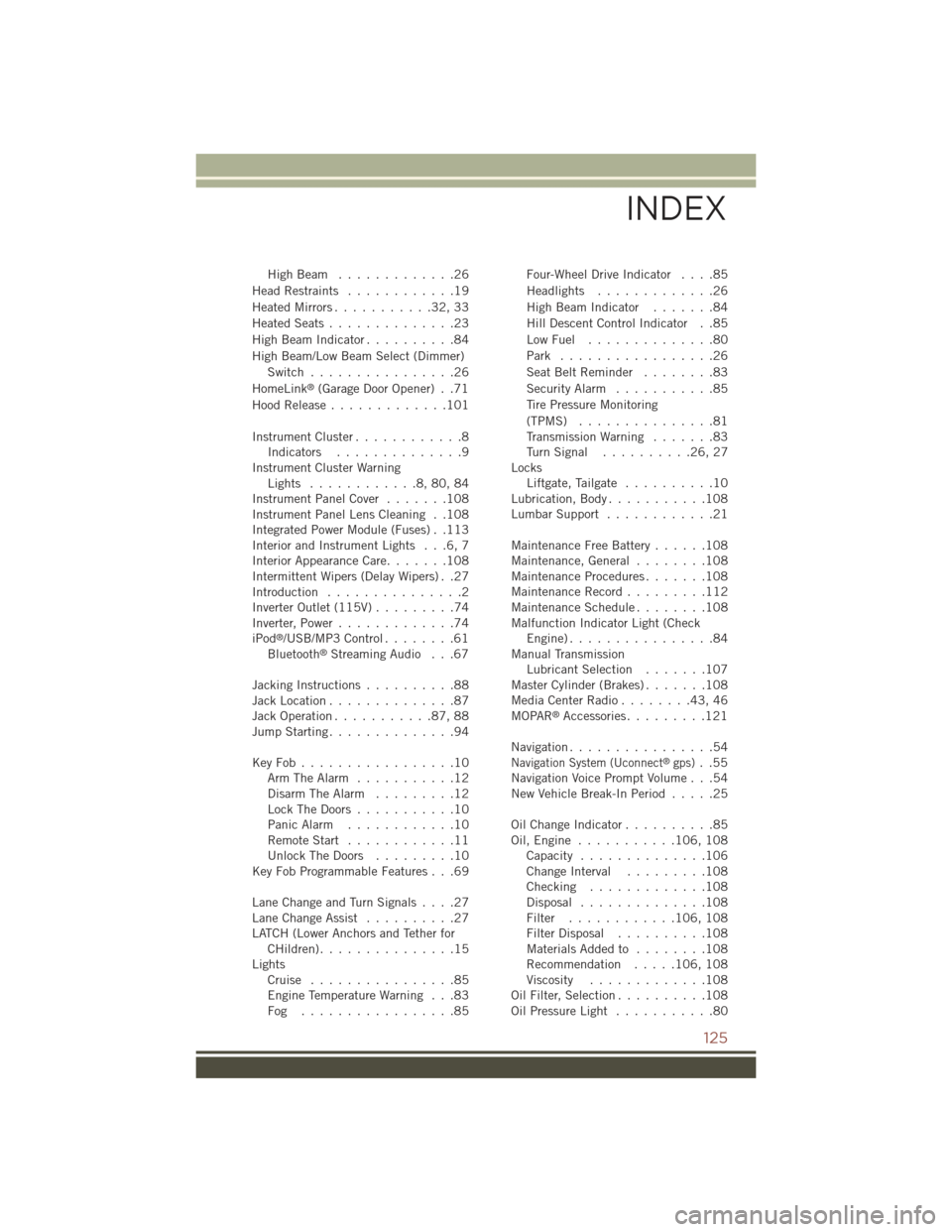
High Beam . . . . . . . . . . . . .26
Head Restraints............19
Heated Mirrors...........32,33
Heated Seats..............23
High Beam Indicator..........84
High Beam/Low Beam Select (Dimmer)
Switch................26
HomeLink®(Garage Door Opener) . .71
Hood Release.............101
Instrument Cluster............8Indicators..............9Instrument Cluster WarningLights . . . . . . . . . . . .8, 80, 84Instrument Panel Cover.......108Instrument Panel Lens Cleaning . .108Integrated Power Module (Fuses) . .113Interior and Instrument Lights . . .6, 7Interior Appearance Care.......108Intermittent Wipers (Delay Wipers) . .27Introduction...............2Inverter Outlet (115V).........74Inverter, Power.............74iPod®/USB/MP3 Control........61Bluetooth®Streaming Audio . . .67
Jacking Instructions..........88Jack Location..............87Jack Operation...........87,88Jump Starting..............94
Key Fob . . . . . . . . . . . . . . . . .10Arm The Alarm...........12Disarm The Alarm.........12Lock The Doors...........10Panic Alarm............10Remote Start . . . . . . . . . . . .11Unlock The Doors . . . . . . . . .10Key Fob Programmable Features . . .69
Lane Change and Turn Signals....27Lane Change Assist..........27LATCH (Lower Anchors and Tether forCHildren). . . . . . . . . . . . . . .15LightsCruise . . . . . . . . . . . . . . . .85Engine Temperature Warning . . .83Fog . . . . . . . . . . . . . . . . .85
Four-Wheel Drive Indicator....85
Headlights.............26
High Beam Indicator.......84
Hill Descent Control Indicator . .85
Low Fuel . . . . . . . . . . . . . .80
Park . . . . . . . . . . . . . . . . .26
Seat Belt Reminder........83
Security Alarm...........85
Tire Pressure Monitoring
(TPMS)...............81Transmission Warning.......83Tu r n S i g n a l . . . . . . . . . . 2 6 , 2 7LocksLiftgate, Tailgate..........10Lubrication, Body...........108Lumbar Support............21
Maintenance Free Battery......108Maintenance, General . . . . . . . .108Maintenance Procedures.......108Maintenance Record . . . . . . . . .112Maintenance Schedule . . . . . . . .108Malfunction Indicator Light (CheckEngine) . . . . . . . . . . . . . . . .84Manual TransmissionLubricant Selection.......107Master Cylinder (Brakes).......108Media Center Radio . . . . . . . .43, 46MOPAR®Accessories.........121
Navigation................54Navigation System (Uconnect®gps)..55Navigation Voice Prompt Volume . . .54New Vehicle Break-In Period.....25
Oil Change Indicator..........85Oil, Engine...........106, 108Capacity..............106Change Interval.........108Checking.............108Disposal..............108Filter............106, 108Filter Disposal..........108Materials Added to........108Recommendation.....106, 108Viscosity.............108Oil Filter, Selection..........108Oil Pressure Light...........80
INDEX
125