tow JEEP COMPASS 2016 1.G Owner's Manual
[x] Cancel search | Manufacturer: JEEP, Model Year: 2016, Model line: COMPASS, Model: JEEP COMPASS 2016 1.GPages: 148, PDF Size: 8.42 MB
Page 96 of 148
JACKING AND TIRE CHANGING
WARNING!
• Do not attempt to change a tire on the side of the vehicle close to movingtraffic. Pull far enough off the road to avoid the danger of being hit when
operating the jack or changing the wheel.
• Being under a jacked-up vehicle is dangerous. The vehicle could slip off the
jack and fall on you. You could be crushed. Never put any part of your body
under a vehicle that is on a jack. If you need to get under a raised vehicle, take
it to a service center where it can be raised on a lift.
• Never start or run the engine while the vehicle is on a jack.
• The jack is designed to be used as a tool for changing tires only. The jack
should not be used to lift the vehicle for service purposes. The vehicle should
be jacked on a firm level surface only. Avoid ice or slippery areas.
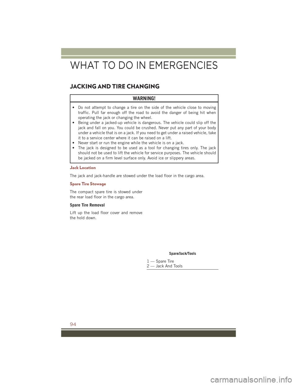
Jack Location
The jack and jack-handle are stowed under the load floor in the cargo area.
Spare Tire Stowage
The compact spare tire is stowed under
the rear load floor in the cargo area.
Spare Tire Removal
Lift up the load floor cover and remove
the hold down.
Spare/Jack/Tools
1 — Spare Tire
2 — Jack And Tools
WHAT TO DO IN EMERGENCIES
94
Page 98 of 148
Jacking Instructions
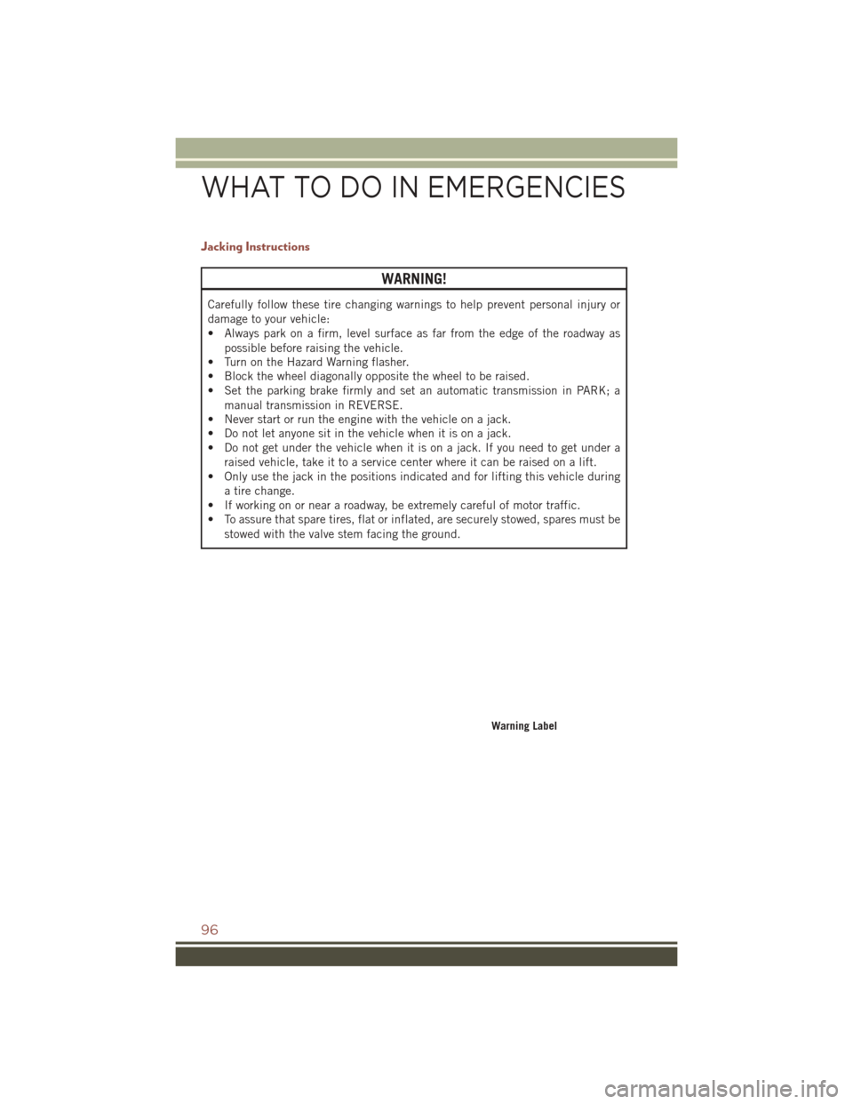
WARNING!
Carefully follow these tire changing warnings to help prevent personal injury or
damage to your vehicle:
• Always park on a firm, level surface as far from the edge of the roadway aspossible before raising the vehicle.
• Turn on the Hazard Warning flasher.
• Block the wheel diagonally opposite the wheel to be raised.
• Set the parking brake firmly and set an automatic transmission in PARK; a
manual transmission in REVERSE.
• Never start or run the engine with the vehicle on a jack.
• Do not let anyone sit in the vehicle when it is on a jack.
• Do not get under the vehicle when it is on a jack. If you need to get under a
raised vehicle, take it to a service center where it can be raised on a lift.
• Only use the jack in the positions indicated and for lifting this vehicle during
a tire change.
• If working on or near a roadway, be extremely careful of motor traffic.
• To assure that spare tires, flat or inflated, are securely stowed, spares must be
stowed with the valve stem facing the ground.
Warning Label
WHAT TO DO IN EMERGENCIES
96
Page 101 of 148
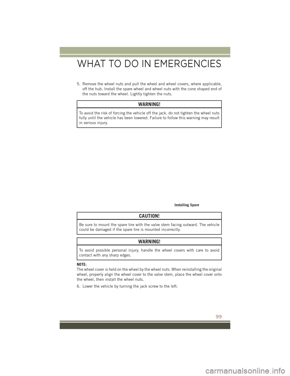
5. Remove the wheel nuts and pull the wheel and wheel covers, where applicable,off the hub. Install the spare wheel and wheel nuts with the cone shaped end of
the nuts toward the wheel. Lightly tighten the nuts.
WARNING!
To avoid the risk of forcing the vehicle off the jack, do not tighten the wheel nuts
fully until the vehicle has been lowered. Failure to follow this warning may result
in serious injury.
CAUTION!
Be sure to mount the spare tire with the valve stem facing outward. The vehicle
could be damaged if the spare tire is mounted incorrectly.
WARNING!
To avoid possible personal injury, handle the wheel covers with care to avoid
contact with any sharp edges.
NOTE:
The wheel cover is held on the wheel by the wheel nuts. When reinstalling the original
wheel, properly align the wheel cover to the valve stem, place the wheel cover onto
the wheel, then install the wheel nuts.
6. Lower the vehicle by turning the jack screw to the left.
Installing Spare
WHAT TO DO IN EMERGENCIES
99
Page 102 of 148
7. Finish tightening the nuts. Push down on the wrench while at the end of thehandle for increased leverage. Tighten the lug nuts in a star pattern until each nut
has been tightened twice. The correct wheel nut torque is 100 ft/lbs (135 N·m).
If you doubt that you have tightened the nuts correctly, have them checked with
a torque wrench by your authorized dealer or service station
8. Remove the wheel blocks and lower the jack until it is free. Release the parking brake. Reassemble the lug wrench to the jack assembly and stow it in the spare
tire area. Secure the assembly using the means provided.
WARNING!
A loose tire or jack thrown forward in a collision or hard stop could endanger the
occupants of the vehicle. Always stow the jack parts and the spare tire in the
places provided.
9. Place the deflated (flat) tire in the cargo area, have the tire repaired or replaced as
soon as possible.
WARNING!
A loose tire thrown forward in a collision or hard stop could injure the occupants
in the vehicle. Have the deflated (flat) tire repaired or replaced immediately.
10. Check the spare tire pressure as soon as possible. Correct the tire pressure as required.
11. After 25 miles (40 km) check the lug nut torque with a torque wrench to ensure that all lug nuts are properly seated against the wheel.
WHAT TO DO IN EMERGENCIES
100
Page 103 of 148
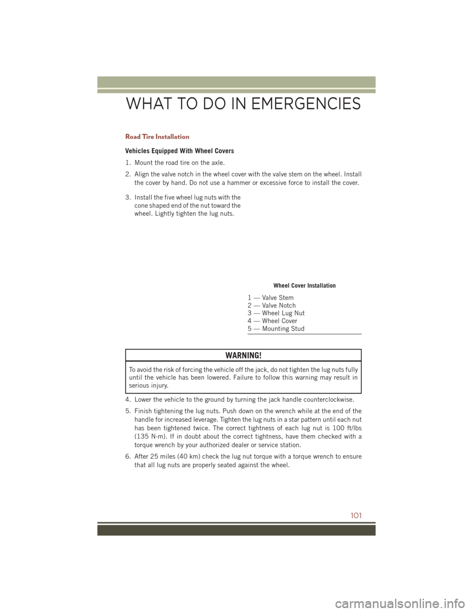
Road Tire Installation
Vehicles Equipped With Wheel Covers
1. Mount the road tire on the axle.
2. Align the valve notch in the wheel cover with the valve stem on the wheel. Installthe cover by hand. Do not use a hammer or excessive force to install the cover.
3. Install the five wheel lug nuts with the cone shaped end of the nut toward the
wheel. Lightly tighten the lug nuts.
WARNING!
To avoid the risk of forcing the vehicle off the jack, do not tighten the lug nuts fully
until the vehicle has been lowered. Failure to follow this warning may result in
serious injury.
4. Lower the vehicle to the ground by turning the jack handle counterclockwise.
5. Finish tightening the lug nuts. Push down on the wrench while at the end of the handle for increased leverage. Tighten the lug nuts in a star pattern until each nut
has been tightened twice. The correct tightness of each lug nut is 100 ft/lbs
(135 N·m). If in doubt about the correct tightness, have them checked with a
torque wrench by your authorized dealer or service station.
6. After 25 miles (40 km) check the lug nut torque with a torque wrench to ensure that all lug nuts are properly seated against the wheel.
Wheel Cover Installation
1 — Valve Stem
2 — Valve Notch
3 — Wheel Lug Nut
4 — Wheel Cover
5 — Mounting Stud
WHAT TO DO IN EMERGENCIES
101
Page 104 of 148
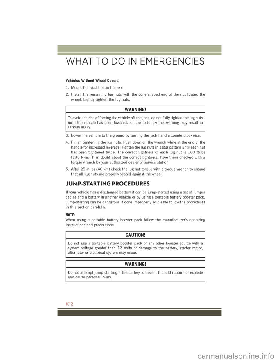
Vehicles Without Wheel Covers
1. Mount the road tire on the axle.
2. Install the remaining lug nuts with the cone shaped end of the nut toward thewheel. Lightly tighten the lug nuts.
WARNING!
To avoid the risk of forcing the vehicle off the jack, do not fully tighten the lug nuts
until the vehicle has been lowered. Failure to follow this warning may result in
serious injury.
3. Lower the vehicle to the ground by turning the jack handle counterclockwise.
4. Finish tightening the lug nuts. Push down on the wrench while at the end of the handle for increased leverage. Tighten the lug nuts in a star pattern until each nut
has been tightened twice. The correct tightness of each lug nut is 100 ft/lbs
(135 N·m). If in doubt about the correct tightness, have them checked with a
torque wrench by your authorized dealer or service station.
5. After 25 miles (40 km) check the lug nut torque with a torque wrench to ensure that all lug nuts are properly seated against the wheel.
JUMP-STARTING PROCEDURES
If your vehicle has a discharged battery it can be jump-started using a set of jumper
cables and a battery in another vehicle or by using a portable battery booster pack.
Jump-starting can be dangerous if done improperly so please follow the procedures
in this section carefully.
NOTE:
When using a portable battery booster pack follow the manufacturer’s operating
instructions and precautions.
CAUTION!
Do not use a portable battery booster pack or any other booster source with a
system voltage greater than 12 Volts or damage to the battery, starter motor,
alternator or electrical system may occur.
WARNING!
Do not attempt jump-starting if the battery is frozen. It could rupture or explode
and cause personal injury.
WHAT TO DO IN EMERGENCIES
102
Page 108 of 148
4. Turn the ignition switch to the ACC or ON/RUN position, but do not start theengine.
5. Press and maintain firm pressure on the brake pedal.
6. Insert the screwdriver or similar tool into the access port, and push and hold the override release lever forward.
7. Move the shift lever to the NEUTRAL position.
8. The vehicle may then be started in NEUTRAL.
9. Reinstall the shift lever override access cover.
TOWING A DISABLED VEHICLE
This section describes procedures for towing a disabled vehicle using a commercial
towing service.
Towing
Condition Wheels OFF
the Ground Manual
Transmission 6-Speed
Automatic
(FWD Only) 6-Speed Au-
tomatic 4WD CVT Auto-
matic Trans- mission
Flat Tow NONE • Trans-
mission
in NEU-
TRAL
• Key in
ACC or
ON/RUN
position If transmis-
sion is oper- able:
• Trans- mission
in NEU-
TRAL
• 25 mph
(40 km/h)
max
speed
• 15 miles
(24 km)
max dis-
tance If transmis-
sion is oper- able:
• Trans- mission
in NEU-
TRAL
• 25 mph
(40 km/h)
max
speed
• 15 miles
(24 km)
max dis-
tance NOT AL-
LOWED
Wheel Lift
or Dolly Tow Rear
NOT AL-
LOWED NOT AL-
LOWED NOT AL-
LOWED
Front FWD Models
ONLY OKNOT AL-
LOWED FWD Models
ONLY
Flatbed ALLBEST
METHOD BEST
METHOD BEST
METHOD BEST
METHOD
Refer to” Towing A Disabled Vehicle” in the Owner’s Manual on the DVD for further
information.
WHAT TO DO IN EMERGENCIES
106
Page 111 of 148
TO OPEN AND CLOSE THE HOOD
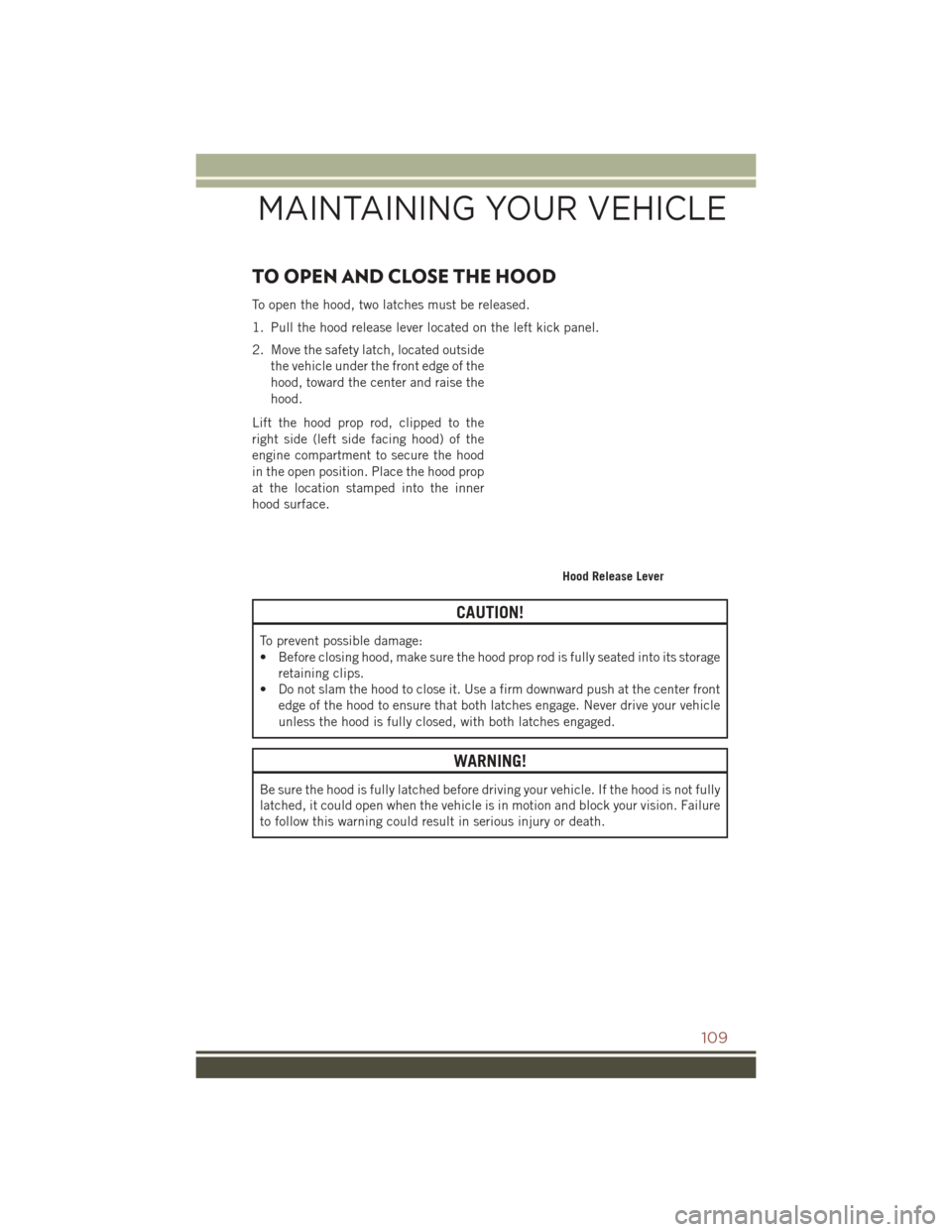
To open the hood, two latches must be released.
1. Pull the hood release lever located on the left kick panel.
2. Move the safety latch, located outsidethe vehicle under the front edge of the
hood, toward the center and raise the
hood.
Lift the hood prop rod, clipped to the
right side (left side facing hood) of the
engine compartment to secure the hood
in the open position. Place the hood prop
at the location stamped into the inner
hood surface.
CAUTION!
To prevent possible damage:
• Before closing hood, make sure the hood prop rod is fully seated into its storage retaining clips.
• Do not slam the hood to close it. Use a firm downward push at the center front
edge of the hood to ensure that both latches engage. Never drive your vehicle
unless the hood is fully closed, with both latches engaged.
WARNING!
Be sure the hood is fully latched before driving your vehicle. If the hood is not fully
latched, it could open when the vehicle is in motion and block your vision. Failure
to follow this warning could result in serious injury or death.
Hood Release Lever
MAINTAINING YOUR VEHICLE
109
Page 118 of 148
MAINTENANCE PROCEDURES
For information on the maintenance procedures for your vehicle, please refer to
“Maintenance Procedures” in “Maintaining Your Vehicle” in your Owner’s Manual or
applicable supplement on the DVD for further details.
MAINTENANCE SCHEDULE
Your vehicle is equipped with an automatic oil change indicator system. The oil
change indicator system will remind you that it is time to take your vehicle in for
scheduled maintenance.
Based on engine operation conditions, the oil change indicator message will
illuminate. This means that service is required for your vehicle. Operating conditions
such as frequent short-trips, trailer tow, extremely hot or cold ambient temperatures
will influence when the “Change Oil” or “Oil Change Required” message is dis-
played. Severe Operating Conditions can cause the change oil message to illuminate
as early as 3,500 miles (5,600 km) since last reset. Have your vehicle serviced as
soon as possible, within the next 500 miles (805 km).
On Electronic Vehicle Information Center (EVIC) equipped vehicles, “Oil Change
Required” will be displayed in the EVIC and a single chime will sound, indicating that
an oil change is necessary.
On Non-EVIC equipped vehicles, “Change Oil” will flash in the instrument cluster
odometer and a single chime will sound, indicating that an oil change is necessary.
Your authorized dealer will reset the oil change indicator message after completing
the scheduled oil change. If a scheduled oil change is performed by someone other
than your authorized dealer, the message can be reset by referring to the steps
described under “Instrument Cluster Warning Lights” in “What To Do In Emergen-
cies” in this guide or “Instrument Cluster Descriptions” or “Electronic Vehicle
Information Center (EVIC)” in “Understanding Your Instrument Panel” in the
Owner’s Manual on your DVD for further information.
NOTE:
Under no circumstances should oil change intervals exceed 10,000 miles
(16,000 km), twelve months or 350 hours of engine run time, whichever comes first.
The 350 hours of engine run or idle time is generally only a concern for fleet
customers.
Severe Duty All Models
Change Engine Oil at 4,000 miles (6,500 km) if the vehicle is operated in a dusty
and off road environment or is operated predominately at idle or only very low engine
RPM’s. This type of vehicle use is considered Severe Duty.
MAINTAINING YOUR VEHICLE
116
Page 120 of 148
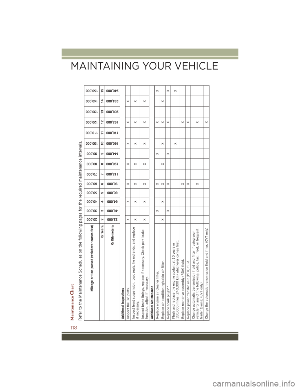
Maintenance ChartRefer to the Maintenance Schedules on the following pages for the required maintenance intervals.
Mileage or time passed (whichever comes first)
20,000
30,000
40,000
50,000
60,000
70,000
80,000
90,000
100,000
110,000
120,000
130,000
140,000
150,000
Or Years: 2 3 4 5 6 7 8 9 10 11 12 13 14 15
Or Kilometers:
32,000
48,000
64,000
80,000
96,000
112,000
128,000
144,000
160,000
176,000
192,000
208,000
224,000
240,000
Additional Inspections
Inspect the CV joints. X X X X X X X
Inspect front suspension, boot seals. tie rod ends, and replace
if necessary. XXX X X X X
Inspect brake linings, replace if necessary. Check park brake
function, adjust if necessary. XXX X X X X
Additional Maintenance
Replace engine air cleaner filter. X X X X X
Replace air conditioning/cabin air filter. X X X X X X X
Replace spark plugs** X X X X X
Flush and replace the engine coolant at 10 years or
150,000 miles (240,000 km) whichever comes first. XX
Replace rear drive assembly (RDA) fluid. X X
Replace power transfer unit (PTU) fluid. X X
Change automatic transmission fluid and filter if using your
vehicle for any of the following: police, taxi, fleet, or frequent
trailer towing. (CVT only) XX
Change the automatic transmission fluid and filter. (CVT only) X
MAINTAINING YOUR VEHICLE
118