ignition JEEP COMPASS 2016 1.G Owner's Manual
[x] Cancel search | Manufacturer: JEEP, Model Year: 2016, Model line: COMPASS, Model: JEEP COMPASS 2016 1.GPages: 148, PDF Size: 8.42 MB
Page 97 of 148

Preparations For Jacking
1. Park the vehicle on a firm level surface, avoiding ice or slippery areas.
WARNING!
Do not attempt to change a tire on the side of the vehicle close to moving traffic,
pull far enough off the road to avoid the danger of being hit when operating the
jack or changing the wheel.
2. Turn on the Hazard Warning flasher.
3. Set the parking brake.
4. Place the shift lever in PARK (automatic transmission) or REVERSE (manual transmission).
5. Turn OFF the ignition.
6. Block both the front and rear of the wheel diagonally opposite of the jacking position. For example, if changing the right front tire, block the left rear wheel.
NOTE:
Passengers should not remain in the ve-
hicle while the vehicle is being jacked.
Wheel Blocked
WHAT TO DO IN EMERGENCIES
95
Page 106 of 148

WARNING!
• Take care to avoid the radiator cooling fan whenever the hood is raised. It canstart anytime the ignition switch is ON. You can be injured by moving fan
blades.
• Remove any metal jewelry such as rings, watch bands and bracelets that could
make an inadvertent electrical contact. You could be seriously injured.
• Batteries contain sulfuric acid that can burn your skin or eyes and generate
hydrogen gas which is flammable and explosive. Keep open flames or sparks
away from the battery.
1. Set the parking brake, shift the automatic transmission into PARK (manual transmission to NEUTRAL) and turn the ignition to LOCK.
2. Turn off the heater, radio, and all unnecessary electrical accessories.
3. If using another vehicle to jump-start the battery, park the vehicle within the jumper cables reach, set the parking brake and make sure the ignition is OFF.
WARNING!
Do not allow vehicles to touch each other as this could establish a ground
connection and personal injury could result.
Jump-Starting Procedure
WARNING!
Failure to follow this jump-starting procedure could result in personal injury or
property damage due to battery explosion.
CAUTION!
Failure to follow these procedures could result in damage to the charging system
of the booster vehicle or the discharged vehicle.
NOTE:
Remove Air Intake before proceeding with this Jump-Starting procedure.
Connecting The Jumper Cables
1. Connect the positive (+)end of the jumper cable to the positive (+)post of the
discharged vehicle.
2. Connect the opposite end of the positive (+)jumper cable to the positive (+)post
of the booster battery.
3. Connect the negative end (-)of the jumper cable to the negative (-)post of the
booster battery.
WHAT TO DO IN EMERGENCIES
104
Page 108 of 148

4. Turn the ignition switch to the ACC or ON/RUN position, but do not start theengine.
5. Press and maintain firm pressure on the brake pedal.
6. Insert the screwdriver or similar tool into the access port, and push and hold the override release lever forward.
7. Move the shift lever to the NEUTRAL position.
8. The vehicle may then be started in NEUTRAL.
9. Reinstall the shift lever override access cover.
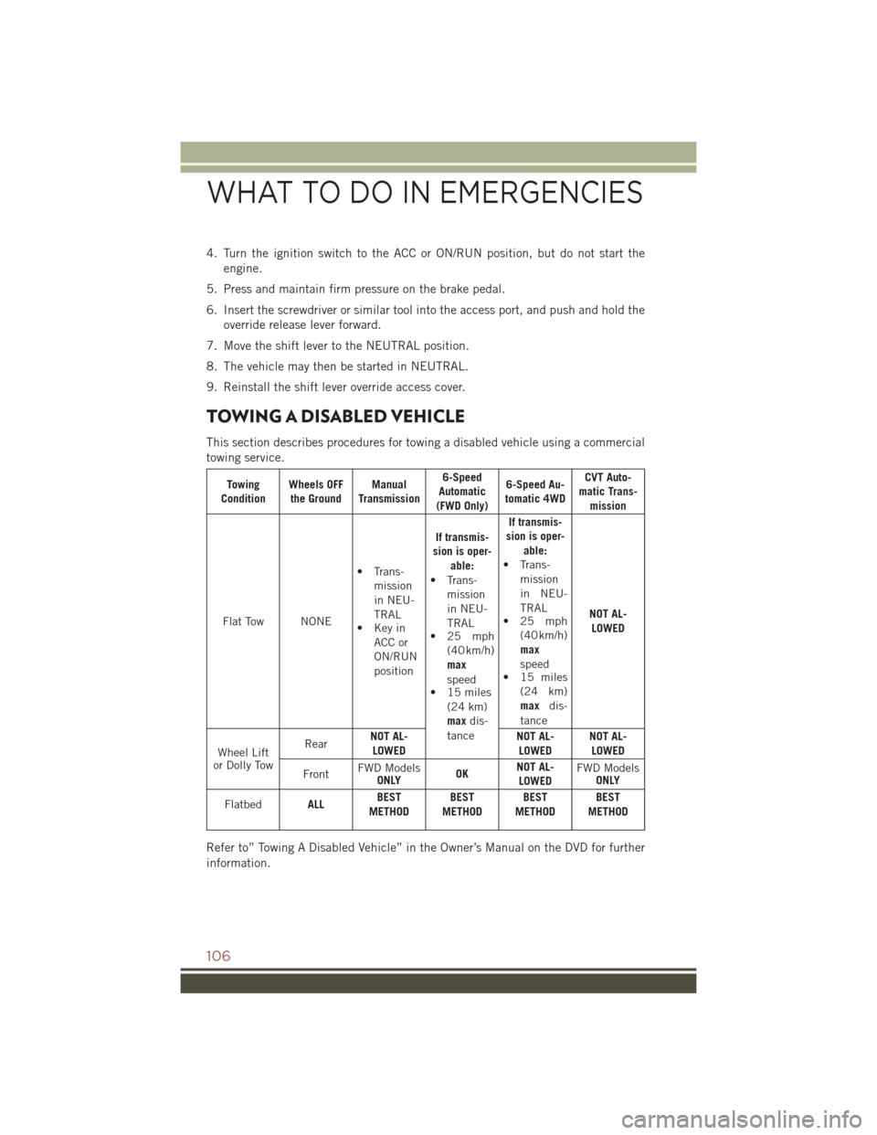
TOWING A DISABLED VEHICLE
This section describes procedures for towing a disabled vehicle using a commercial
towing service.
Towing
Condition Wheels OFF
the Ground Manual
Transmission 6-Speed
Automatic
(FWD Only) 6-Speed Au-
tomatic 4WD CVT Auto-
matic Trans- mission
Flat Tow NONE • Trans-
mission
in NEU-
TRAL
• Key in
ACC or
ON/RUN
position If transmis-
sion is oper- able:
• Trans- mission
in NEU-
TRAL
• 25 mph
(40 km/h)
max
speed
• 15 miles
(24 km)
max dis-
tance If transmis-
sion is oper- able:
• Trans- mission
in NEU-
TRAL
• 25 mph
(40 km/h)
max
speed
• 15 miles
(24 km)
max dis-
tance NOT AL-
LOWED
Wheel Lift
or Dolly Tow Rear
NOT AL-
LOWED NOT AL-
LOWED NOT AL-
LOWED
Front FWD Models
ONLY OKNOT AL-
LOWED FWD Models
ONLY
Flatbed ALLBEST
METHOD BEST
METHOD BEST
METHOD BEST
METHOD
Refer to” Towing A Disabled Vehicle” in the Owner’s Manual on the DVD for further
information.
WHAT TO DO IN EMERGENCIES
106
Page 123 of 148

FUSES
WARNING!
• When replacing a blown fuse, always use an appropriate replacement fuse withthe same amp rating as the original fuse. Never replace a fuse with another
fuse of higher amp rating. Never replace a blown fuse with metal wires or any
other material. Failure to use proper fuses may result in serious personal injury,
fire and/or property damage.
• Before replacing a fuse, make sure that the ignition is off and that all the other
services are switched off and/or disengaged.
• If the replaced fuse blows again, contact an authorized dealer.
• If a general protection fuse for safety systems (air bag system, braking system),
power unit systems (engine system, gearbox system) or steering system blows,
contact an authorized dealer.
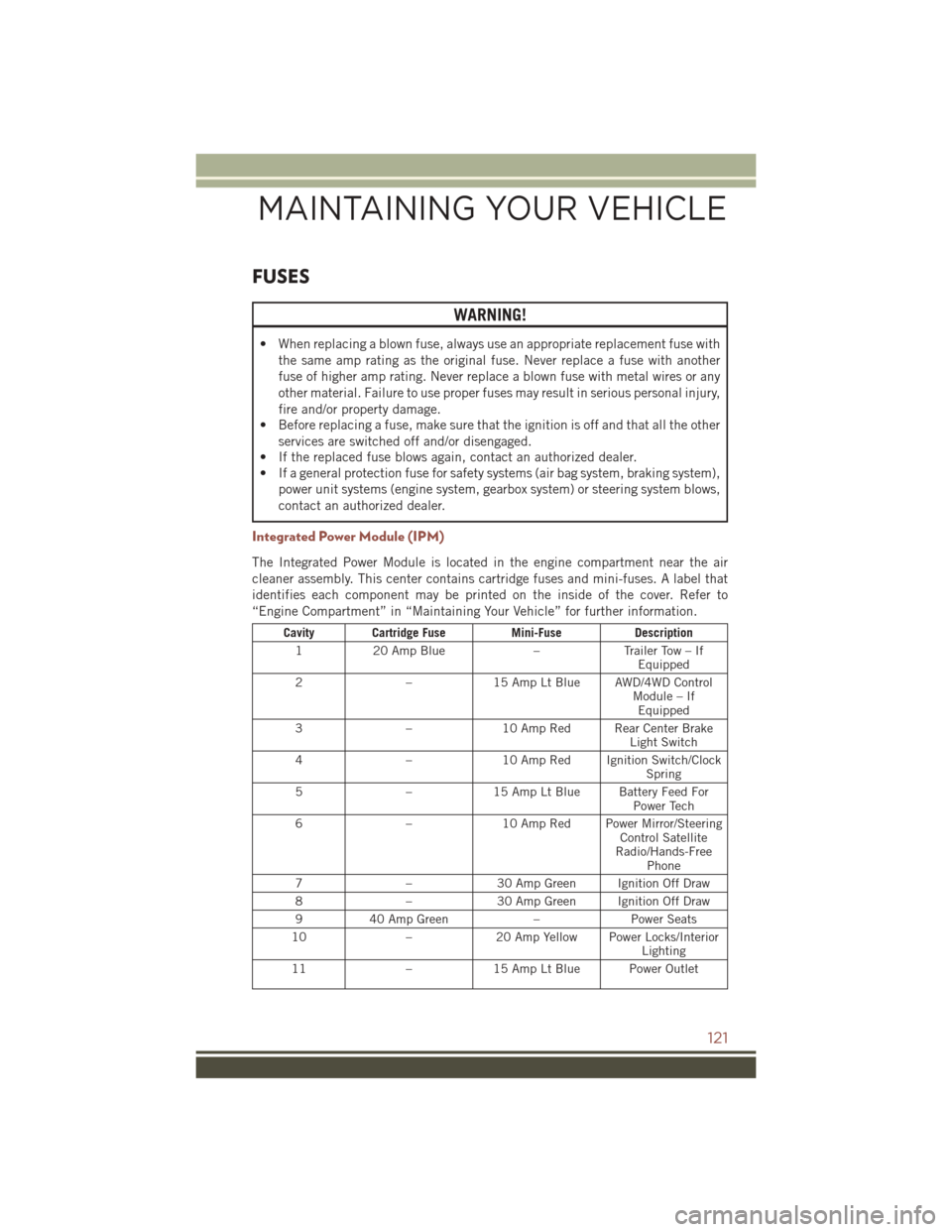
Integrated Power Module (IPM)
The Integrated Power Module is located in the engine compartment near the air
cleaner assembly. This center contains cartridge fuses and mini-fuses. A label that
identifies each component may be printed on the inside of the cover. Refer to
“Engine Compartment” in “Maintaining Your Vehicle” for further information.
Cavity Cartridge Fuse Mini-FuseDescription
1 20 Amp Blue –Trailer Tow – If
Equipped
2 –15 Amp Lt Blue AWD/4WD Control
Module – IfEquipped
3 –10 Amp Red Rear Center Brake
Light Switch
4 –10 Amp Red Ignition Switch/Clock
Spring
5 –15 Amp Lt Blue Battery Feed For
Power Tech
6 –10 Amp Red Power Mirror/Steering
Control Satellite
Radio/Hands-Free Phone
7 –30 Amp Green Ignition Off Draw
8 –30 Amp Green Ignition Off Draw
9 40 Amp Green –Power Seats
10 –20 Amp Yellow Power Locks/Interior
Lighting
11 –15 Amp Lt Blue Power Outlet
MAINTAINING YOUR VEHICLE
121