wheel JEEP COMPASS 2016 1.G User Guide
[x] Cancel search | Manufacturer: JEEP, Model Year: 2016, Model line: COMPASS, Model: JEEP COMPASS 2016 1.GPages: 148, PDF Size: 8.42 MB
Page 3 of 148
INTRODUCTION/WELCOMEWELCOME FROM FCA US LLC...... 2
CONTROLS AT A GLANCEDRIVER COCKPIT.............. 6
INSTRUMENT CLUSTER .......... 8
GETTING STARTEDKEYFOB ................... 10
REMOTE START............... 11
VEHICLE SECURITY ALARM ....... 12
SEAT BELT SYSTEMS ........... 13
SUPPLEMENTAL RESTRAINT SYSTEM
(SRS) — AIR BAGS ............ 14
CHILD RESTRAINTS ............ 18
HEAD RESTRAINTS ............. 22
FRONT SEATS ................ 23
REAR SEATS ................ 26
HEATEDSEATS ............... 27
TILT STEERING COLUMN ......... 28
OPERATING YOUR VEHICLEENGINE BREAK-IN
RECOMMENDATIONS........... 29
MULTIFUNCTION LEVER ......... 30
WINDSHIELD WIPERS AND
WASHERS .................. 32
ELECTRONIC SPEED CONTROL ..... 34
PARKVIEW REAR BACK-UP CAMERA.. 37
CONTINUOUSLY VARIABLE AUTOMATIC
TRANSMISSION (CVT) ........... 37
SIX-SPEED AUTOMATIC
TRANSMISSION ............... 38
MANUAL CLIMATE CONTROLS ...... 38
AUTOMATIC TEMPERATURE CONTROLS
(ATC) ..................... 39
POWER SUNROOF ............. 40
ELECTRONICSYOUR VEHICLE'S SOUND SYSTEM . . . 42
UCONNECT 130............... 44
UCONNECT 130 WITH SiriusXM SATELLITE
RADIO ..................... 46
UCONNECT 230 ............... 49
UCONNECT 430/430N ........... 52
SiriusXM SATELLITE RADIO/TRAVEL
LINK ...................... 64
STEERING WHEEL AUDIO CONTROLS.. 68
AUX/USB/MP3 CONTROL ......... 69
UCONNECT PHONE ............. 70
UCONNECT VOICE COMMAND ...... 72
Bluetooth STREAMING AUDIO ...... 75
ELECTRONIC VEHICLE INFORMATION
CENTER (EVIC) ............... 75
PROGRAMMABLE FEATURES ....... 76
UNIVERSAL GARAGE DOOR OPENER
(HomeLink) ................. 78
POWER INVERTER ............. 81
POWER OUTLET .............. 82
OFF-ROAD CAPABILITIES
FOUR-WHEEL DRIVE OPERATION . . . 83
UTILITY
TRAILER TOWING WEIGHTS (MAXIMUM
TRAILER WEIGHT RATINGS) ....... 85
RECREATIONAL TOWING (BEHIND
MOTORHOME, ETC.) ............ 86
WHAT TO DO IN EMERGENCIES
ROADSIDE ASSISTANCE .......... 87
INSTRUMENT CLUSTER WARNING
LIGHTS .................... 87
INSTRUMENT CLUSTER INDICATOR
LIGHTS .................... 91
IF YOUR ENGINE OVERHEATS ...... 93
AUTOMATIC TRANSMISSION
OVERHEATING ............... 93
JACKING AND TIRE CHANGING ..... 94
JUMP-STARTING PROCEDURES .... 102
SHIFT LEVER OVERRIDE ........ 105
TOWING A DISABLED VEHICLE .... 106
FREEING A STUCK VEHICLE ...... 107
ENHANCED ACCIDENT RESPONSE
SYSTEM (EARS) .............. 108
EVENT DATA RECORDER (EDR) .... 108
MAINTAINING YOUR VEHICLE
TO OPEN AND CLOSE THE HOOD . . . 109
ENGINE COMPARTMENT — 2.0L . . . 110
ENGINE COMPARTMENT — 2.4L . . . 112
FLUID CAPACITIES............ 114
FLUIDS, LUBRICANTS, AND GENUINE
PARTS .................... 114
MAINTENANCE PROCEDURES ..... 116
MAINTENANCE SCHEDULE ....... 116
FUSES ................... 121
TIRES — GENERAL INFORMATION . . 123
REPLACEMENT BULBS ......... 126
CUSTOMER ASSISTANCE
FCA US LLC CUSTOMER CENTER . . . 127
FCA CANADA INC. CUSTOMER
CENTER.................. 127
ASSISTANCE FOR THE HEARING
IMPAIRED ................. 127
PUBLICATIONS ORDERING ....... 127
REPORTING SAFETY DEFECTS IN THE
UNITEDSTATES .............. 128
MOPAR® ACCESSORIES
AUTHENTIC ACCESSORIES BY
MOPAR ................... 129
FAQ
FREQUENTLY ASKED QUESTIONS . . . 130
INDEX.................. 132
TABLE OF CONTENTS
Page 8 of 148
DRIVER COCKPIT
1. Electronic Vehicle Information Center (EVIC) Controls pg. 75
2. Turn Signal/Lights Lever (behind steering wheel) pg. 30
3. Instrument Cluster pg. 8
4. Electronic Vehicle Information Center (EVIC) Display
5. Tachometer
6. Electronic Speed Control pg. 34
7. Wiper/Washer Lever pg. 32
8. Audio System pg. 42
9. Upper Storage
CONTROLS AT A GLANCE
6
Page 9 of 148
10. Lower Storage
11. Climate Controls pg. 38
12. Power Outlet pg. 82
13. Shift Lever pg. 38
14. Switch Panel• Heated Seat Switches pg. 27
• Electronic Stability Control (ESC) OFF pg. 92
• Hazard Switch
15. Ignition Switch (behind steering wheel)
16. Power Mirrors
17. Power Windows
18. Power Door Locks
CONTROLS AT A GLANCE
7
Page 16 of 148
SUPPLEMENTAL RESTRAINT SYSTEM (SRS) — AIR
BAGS
Air Bag System Components
Your vehicle may be equipped with the following air bag system components:
• Occupant Restraint Controller (ORC)
• Air Bag Warning Light
• Steering Wheel and Column
• Instrument Panel
• Knee Impact Bolsters
• Advanced Front Air Bags
• Supplemental Side Air Bags
• Front and Side Impact Sensors
• Seat Belt Pretensioners
• Seat Belt Buckle Switch
• Seat Track Position Sensors
Advanced Front Air Bags
• This vehicle has Advanced Front Air Bags for both the driver and front passengeras a supplement to the seat belt restraint systems. The Advanced Front Air Bags
will not deploy in every type of collision.
• Advanced Front Air Bags are designed to provide additional protection by supplementing the seat belts. Advanced Front Air Bags are not expected to reduce
the risk of injury in rear, side, or rollover collisions.
• The Advanced Front Air Bags will not deploy in all frontal collisions, including some that may produce substantial vehicle damage — for example, some pole
collisions, truck underrides, and angle offset collisions.
• On the other hand, depending on the type and location of impact, Advanced Front Air Bags may deploy in crashes with little vehicle front-end damage but that
produce a severe initial deceleration.
• Because air bag sensors measure vehicle deceleration over time, vehicle speed and damage by themselves are not good indicators of whether or not an air bag
should have deployed.
• Seat belts are necessary for your protection in all collisions, and also are needed to help keep you in position, away from an inflating air bag.
• After any collision, the vehicle should be taken to an authorized dealer immedi- ately.
• Do not drive your vehicle after the air bags have deployed. If you are involved in another collision, the air bags will not be in place to protect you.
GETTING STARTED
14
Page 17 of 148
• If it is necessary to modify the air bag system for persons with disabilities, contactyour authorized dealer.
• Refer to the Owner's Manual on the DVD for further details regarding the Supplemental Restraint System (SRS).
WARNING!
• Relying on the air bags alone could lead to more severe injuries in a collision. The air bags work with your seat belt to restrain you properly. In some
collisions, the air bags won't deploy at all. Always wear your seat belts even
though you have air bags.
• Being too close to the steering wheel or instrument panel during Advanced
Front Air Bag deployment could cause serious injury, including death. Air bags
need room to inflate. Sit back, comfortably extending your arms to reach the
steering wheel or instrument panel.
• No objects should be placed over or near the air bag on the instrument panel
or steering wheel because any such objects could cause harm if the vehicle is
in a collision severe enough to cause the air bag to inflate.
Supplemental Side Air Bags
• This vehicle is equipped with Supplemental Seat-Mounted Side Air Bags (SABs)
located in the outboard side of the front seats. The SABs are marked with a SRS
AIRBAG or AIRBAG label sewn into the outboard side of the seats.
• This vehicle is equipped with Supplemental Side Air Bag Inflatable Curtains (SABICs) located above the side windows. The trim covering the SABICs is labeled
SRS AIRBAG or AIRBAG. The SABICs may help reduce the risk of partial or
complete ejection of vehicle occupants through side windows in certain side
impact events.
• The SABICs and SABs (“Side Air Bags”) are designed to activate in certain side impacts and certain rollover events. The Occupant Restraint Controller (“ORC”)
determines whether the deployment of the Side Air Bags in a particular side
impact or rollover event is appropriate, based on the severity and type of collision.
Vehicle damage by itself is not a good indicator of whether or not Side Air Bags
should have deployed.
GETTING STARTED
15
Page 30 of 148
WARNING!
• Persons who are unable to feel pain to the skin because of advanced age,chronic illness, diabetes, spinal cord injury, medication, alcohol use, exhaus-
tion or other physical condition must exercise care when using the seat heater.
It may cause burns even at low temperatures, especially if used for long periods
of time.
• Do not place anything on the seat or seatback that insulates against heat, such
as a blanket or cushion. This may cause the seat heater to overheat. Sitting in
a seat that has been overheated could cause serious burns due to the increased
surface temperature of the seat.
TILT STEERING COLUMN
This feature allows you to tilt the steering column upward or downward. The tilt
steering column lever is located on the left side of the steering column, below the
turn signal lever.
Push down on the lever to unlock the steering column. With one hand firmly on the
steering wheel, move the steering column up or down, as desired. Push the lever up
to lock the steering column firmly in place.
WARNING!
Do not adjust the steering column while driving. Adjusting the steering column
while driving or driving with the steering column unlocked, could cause the driver
to lose control of the vehicle. Failure to follow this warning may result in serious
injury or death.
Steering Column Lever
GETTING STARTED
28
Page 36 of 148
Rear Window Wiper/Washer
The rear wiper/washer is controlled by a rotary switch located on the center portion of
the control lever. The control lever is located on the right side of the steering column.
Rotate the center portion of the lever upward to the first detent position for rear wiper
operation.
NOTE:
The rear wiper operates in an intermittent mode only.
Rotate the center portion of the lever past the first detent to activate the rear washer.
The washer pump and the wiper will continue to operate as long as the switch is held
(for a maximum of 10 seconds). Upon release, the wiper will continue to cycle two
times before returning to the set position.
If the rear wiper is operating when the ignition is turned OFF, the wiper will
automatically return to the “park” position if power accessory delay is active. Power
accessory delay can be cancelled by opening the door, if this happens the rear wiper
will stop at its current position and will not go to “park”.
ELECTRONIC SPEED CONTROL
When engaged, the Electronic Speed Control takes over accelerator operations at
speeds greater than 25 mph (40 km/h).
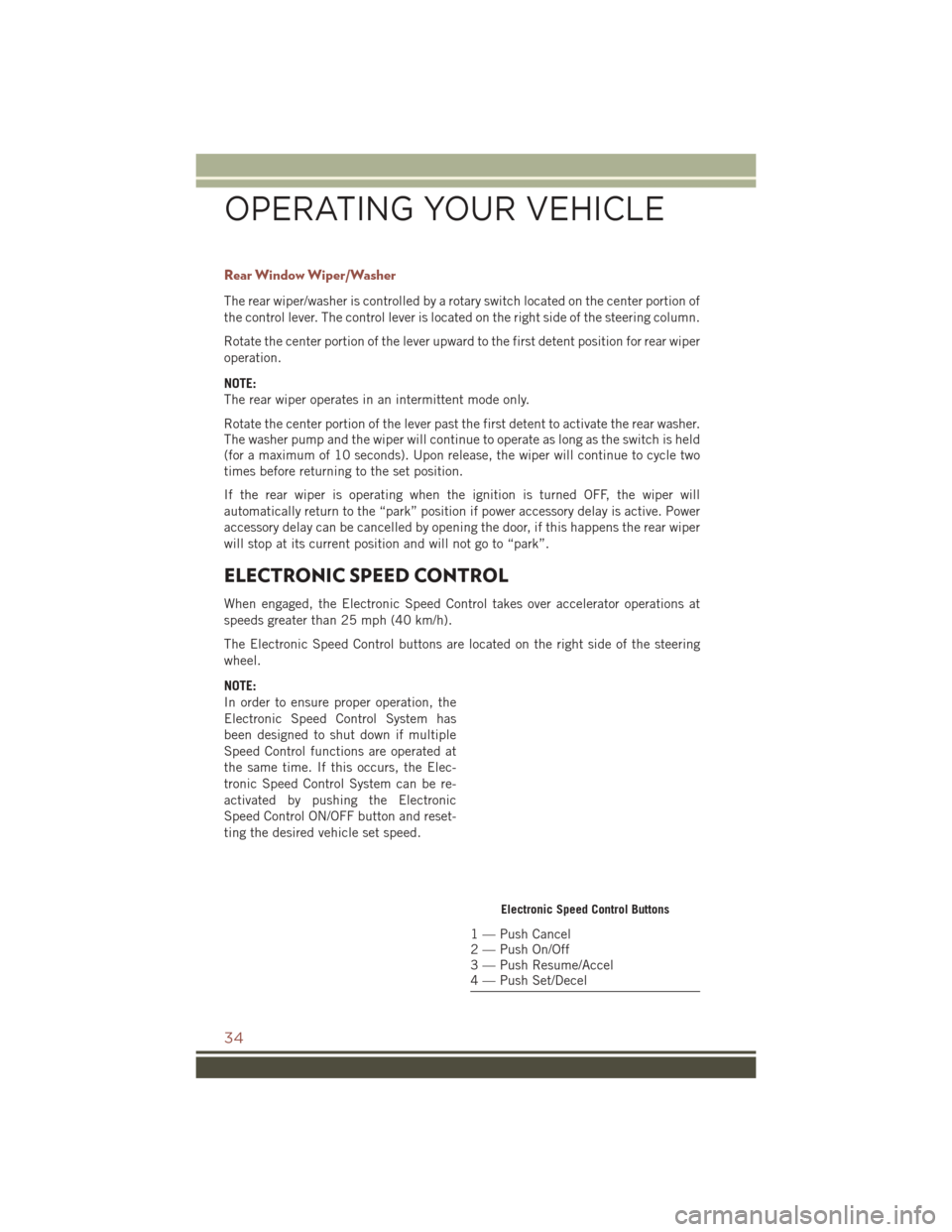
The Electronic Speed Control buttons are located on the right side of the steering
wheel.
NOTE:
In order to ensure proper operation, the
Electronic Speed Control System has
been designed to shut down if multiple
Speed Control functions are operated at
the same time. If this occurs, the Elec-
tronic Speed Control System can be re-
activated by pushing the Electronic
Speed Control ON/OFF button and reset-
ting the desired vehicle set speed.
Electronic Speed Control Buttons
1 — Push Cancel
2 — Push On/Off
3 — Push Resume/Accel
4 — Push Set/Decel
OPERATING YOUR VEHICLE
34
Page 44 of 148
YOUR VEHICLE'S SOUND SYSTEM
1. Uconnect Voice Command Button pg. 72
2. Uconnect Phone Button pg. 70
3. Steering Wheel Audio Controls (Right – Behind Steering Wheel) pg. 68
4. Steering Wheel Audio Controls (Left – Behind Steering Wheel) pg. 68
ELECTRONICS
42
Page 70 of 148
• To access Travel Link, push the MENU button on the faceplate, then the “TravelLink” button on the touchscreen.
1 – Favorites View and store your favorite location, theater and sport
teams for quick access.
2 – Forecast View detailed weather conditions, forecasts and ski/
snowboarding conditions at resorts.
3 – Ski Info View ski and snowboarding conditions at ski resorts.
4 – Fuel Prices View detailed price information for fuel stations.
5 – Movies View information on movies that are playing at theaters.
6 – Sports View sports scores and upcoming events for all major
sports.
STEERING WHEEL AUDIO CONTROLS
The steering wheel audio controls are located on the rear surface of the steering
wheel.
Right Switch
• Push the switch up or down to in-
crease or decrease the volume.
• Push the button in the center to change modes AM/FM/CD/SAT.
Left Switch
• Push the switch up or down to searchfor the next listenable station.
• Push the button in the center to select the next preset station.
Steering Wheel Audio Controls (Rearview Of Steering Wheel)
ELECTRONICS
68
Page 74 of 148
Receiving A Call — Accept (And End)
• When an incoming call rings/is announced on Uconnect, push the “Phone”button
.
• To end a call, push the “Phone” button
.
Mute (Or Unmute) Microphone During Call
• During a call, push the “Voice Command” button.
• After the BEEP, say “mute” (or “mute off”).
Transfer Ongoing Call Between Handset And Vehicle
• During a call, push the “Voice Command” button.
• After the BEEP, say “transfer call.”
Changing The Volume
• Start a dialogue by pushing the “Phone” button, then adjust the volume
during a normal call.
• Use the radio ON/OFF VOLUME rotary knob to adjust the volume to a comfortable level while the Uconnect system is speaking. Please note the volume setting for
Uconnect is different than the audio system.
WARNING!
• Any voice commanded system should be used only in safe driving conditions following applicable laws regarding phone use. Your attention should be
focused on safely operating the vehicle. Failure to do so may result in a
collision causing you and others to be severely injured or killed.
• In an emergency, to use Uconnect Phone, your mobile phone must be:
• turned on
• paired to Uconnect Phone
• have network coverage
UCONNECT VOICE COMMAND
Voice Command Operation
The Uconnect Voice Command system allows you to control your AM, FM radio,
satellite radio, disc player, HDD, Uconnect Phone, a memo recorder, and supported
portable media devices.
• When you push the “Voice Command” button
located on the radio faceplate
or steering wheel, you will hear a beep. The beep is your signal to give a command.
If you do not say a command within a few seconds, the system will present you with
a list of options. If you ever want to interrupt the system while it lists options, push
the “Voice Command” button
, listen for the BEEP, and say your command.
ELECTRONICS
72