light JEEP COMPASS 2018 Owner handbook (in English)
[x] Cancel search | Manufacturer: JEEP, Model Year: 2018, Model line: COMPASS, Model: JEEP COMPASS 2018Pages: 348, PDF Size: 6.03 MB
Page 37 of 348
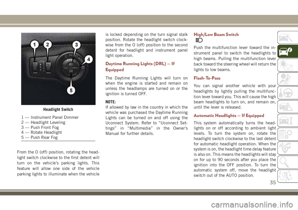
From the O (off) position, rotating the head-
light switch clockwise to the first detent will
turn on the vehicle’s parking lights. This
feature will allow one side of the vehicle
parking lights to illuminate when the vehicleis locked depending on the turn signal stalk
position. Rotate the headlight switch clock-
wise from the O (off) position to the second
detent for headlight and instrument panel
light operation.
Daytime Running Lights (DRL) — If
Equipped
The Daytime Running Lights will turn on
when the engine is started and remain on
unless the headlamps are turned on or the
ignition is turned OFF.
NOTE:
If allowed by law in the country in which the
vehicle was purchased the Daytime Running
Lights can be turned on and off using the
Uconnect System. Refer to “Uconnect Set-
tings” in “Multimedia” in the Owner’s
Manual for further details.
High/Low Beam Switch
Push the multifunction lever toward the in-
strument panel to switch the headlights to
high beams. Pulling the multifunction lever
back toward the steering wheel will return the
lights to low beams.
Flash-To-Pass
You can signal another vehicle with your
headlights by lightly pulling the multifunc-
tion lever toward you. This will cause the high
beam headlights to turn on, and remain on,
until the lever is released.
Automatic Headlights — If Equipped
This system automatically turns the head-
lights on or off according to ambient light
levels. To turn the system on, rotate the
headlight switch clockwise to the last detent
for automatic headlight operation. When the
system is on, the headlight time delay feature
is also on. This means the headlights will stay
on for up to 90 seconds after you place the
ignition into the OFF position. To turn the
automatic system off, move the headlight
switch out of the AUTO position.
Headlight Switch
1 — Instrument Panel Dimmer
2 — Headlight Leveling
3 — Push Front Fog
4 — Rotate Headlight
5 — Push Rear Fog
35
Page 38 of 348
NOTE:
The engine must be running before the head-
lights will come on in the automatic mode.
Headlight Time Delay
This feature provides the safety of headlight
illumination for up to 90 seconds (program-
mable) when leaving your vehicle in an unlit
area.
To activate the delay feature, place the igni-
tion in the OFF position while the headlights
are still on. Then, turn off the headlights
within 45 seconds. The delay interval begins
when the headlight switch is turned off.
If you turn the headlights or parking lights on,
or place the ignition in ACC or RUN, the
system will cancel the delay.
If you turn the headlights off before the
ignition, they will turn off in the normal
manner.NOTE:
• The lights must be turned off within
45 seconds of placing the ignition in the
OFF position to activate this feature. If the
headlight switch is in the AUTO position
prior to turning the ignition OFF, there is no
need to turn the headlight switch to off to
activate Headlight Delay.
• The headlight delay time is programmable
using the Uconnect System. Refer to
“Uconnect Settings” in “Multimedia” in
the Owner’s Manual for further details.
Front And Rear Fog Lights — If Equipped
The fog light switches are built into the head-
light switch.
To activate the front fog lights, push the
upper half of the headlight switch. To turn off
the front fog lights, push the upper half of the
headlight switch a second time.
To activate the rear fog lights, push the
lower half of the headlight switch. To turn off
the rear fog lights, push the lower half of the
headlight switch a second time.NOTE:
To turn on the rear fog lamps, the low beam
lamps or front fog lamps must first be active.
An indicator light in the instrument cluster
illuminates when the fog lights are turned on.
Multifunction Lever
The multifunction lever controls the opera-
tion of the turn signals, headlight beam se-
lection and passing lights. The multifunction
lever is located on the left side of the steering
column.
Turn Signals
Move the multifunction lever up or down and
the arrows on each side of the instrument
cluster display flash to show proper operation
of the front and rear turn signal lights.
NOTE:
• If either light remains on and does not
flash, or there is a very fast flash rate, check
for a defective outside light bulb. If an
indicator fails to light when the lever is
moved, it would suggest that the indicator
bulb is defective.
GETTING TO KNOW YOUR VEHICLE
36
Page 39 of 348
• A “Turn Signal On” message will appear in
the instrument cluster display and a con-
tinuous chime will sound if the vehicle is
driven more than 1 mile (1.6 km) with
either turn signal on.
• When the Daytime Running Lights are on
and a turn signal is activated, the Daytime
Running Lamp will turn off on the side of
the vehicle in which the turn signal is
flashing. The Daytime Running Lamp will
turn back on when the turn signal is turned
off.
Lane Change Assist
Tap the lever up or down once, without mov-
ing beyond the detent, and the turn signal
(right or left) will flash three times then
automatically turn off.
Headlight Leveling System — If Equipped
Your vehicle may be equipped with a head-
light leveling system. This system allows the
driver to maintain proper headlight beam
position with the road surface regardless of
vehicle load.
The control switch is located on the instru-
ment panel next to the dimmer control.
To operate, rotate the control switch until the
appropriate number, which corresponds to
the load listed on the chart, aligns with the
indicator line on the switch.
0/1Driver only, or driver
and front passenger.
2All seating positions
occupied, plus an
evenly distributed
load in the luggage
compartment. The
total weight of pas-
sengers and load
does not exceed the
maximum load ca-
pacity of the vehicle.
3Driver, plus an evenly
distributed load in
the luggage compart-
ment. The total
weight of the driver
and load does not
exceed the maximum
load capacity of the
vehicle.
WIPER AND WASHERS
Windshield Wiper Stalk
1 — Rear Wiper Operation
2 — Front Wiper Operation
37
Page 47 of 348
Icon Description
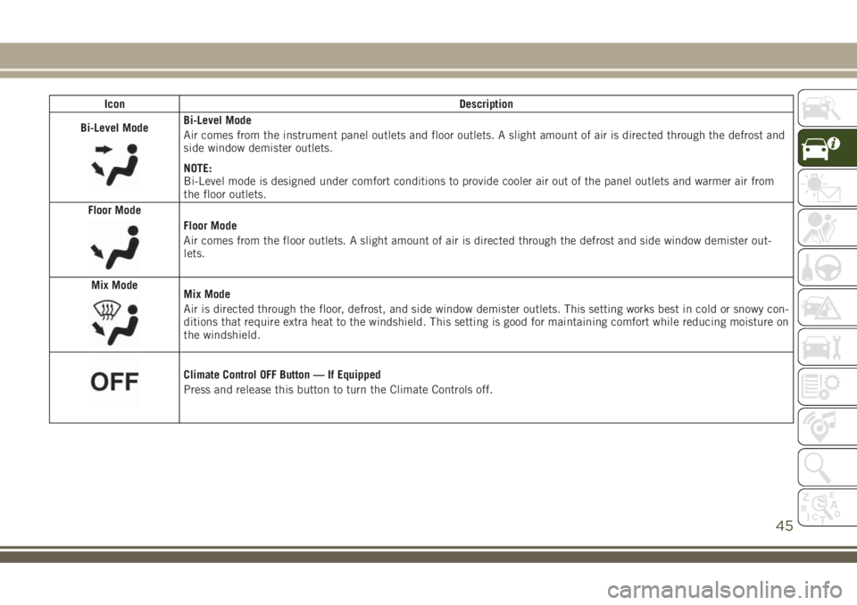
Bi-Level Mode
Bi-Level Mode
Air comes from the instrument panel outlets and floor outlets. A slight amount of air is directed through the defrost and
side window demister outlets.
NOTE:
Bi-Level mode is designed under comfort conditions to provide cooler air out of the panel outlets and warmer air from
the floor outlets.
Floor Mode
Floor Mode
Air comes from the floor outlets. A slight amount of air is directed through the defrost and side window demister out-
lets.
Mix Mode
Mix Mode
Air is directed through the floor, defrost, and side window demister outlets. This setting works best in cold or snowy con-
ditions that require extra heat to the windshield. This setting is good for maintaining comfort while reducing moisture on
the windshield.
Climate Control OFF Button — If Equipped
Press and release this button to turn the Climate Controls off.
45
Page 50 of 348
WINDOWS
Power Window Controls
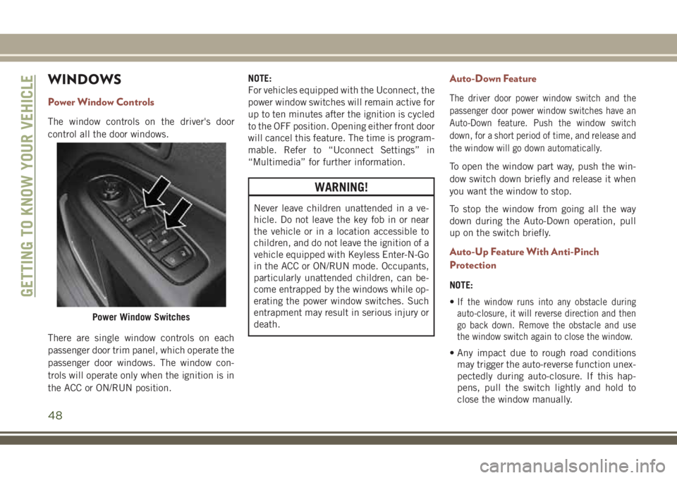
The window controls on the driver's door
control all the door windows.
There are single window controls on each
passenger door trim panel, which operate the
passenger door windows. The window con-
trols will operate only when the ignition is in
the ACC or ON/RUN position.NOTE:
For vehicles equipped with the Uconnect, the
power window switches will remain active for
up to ten minutes after the ignition is cycled
to the OFF position. Opening either front door
will cancel this feature. The time is program-
mable. Refer to “Uconnect Settings” in
“Multimedia” for further information.
WARNING!
Never leave children unattended in a ve-
hicle. Do not leave the key fob in or near
the vehicle or in a location accessible to
children, and do not leave the ignition of a
vehicle equipped with Keyless Enter-N-Go
in the ACC or ON/RUN mode. Occupants,
particularly unattended children, can be-
come entrapped by the windows while op-
erating the power window switches. Such
entrapment may result in serious injury or
death.
Auto-Down Feature
The driver door power window switch and the
passenger door power window switches have an
Auto-Down feature. Push the window switch
down, for a short period of time, and release and
the window will go down automatically.
To open the window part way, push the win-
dow switch down briefly and release it when
you want the window to stop.
To stop the window from going all the way
down during the Auto-Down operation, pull
up on the switch briefly.
Auto-Up Feature With Anti-Pinch
Protection
NOTE:
•
If the window runs into any obstacle during
auto-closure, it will reverse direction and then
go back down. Remove the obstacle and use
the window switch again to close the window.
• Any impact due to rough road conditions
may trigger the auto-reverse function unex-
pectedly during auto-closure. If this hap-
pens, pull the switch lightly and hold to
close the window manually.
Power Window Switches
GETTING TO KNOW YOUR VEHICLE
48
Page 51 of 348
WARNING!
There is no anti-pinch protection when the
window is almost closed. To avoid personal
injury be sure to clear your arms, hands,
fingers and all objects from the window
path before closing.
Reset Auto-Up
Should the Auto-Up feature stop working, the
window probably needs to be reset. To reset
Auto-Up:
1. Pull the window switch up to close the
window completely and continue to hold
the switch up for an additional two sec-
onds after the window is closed.
2. Push the window switch down firmly to
open the window completely and continue
to hold the switch down for an additional
two seconds after the window is fully
open.
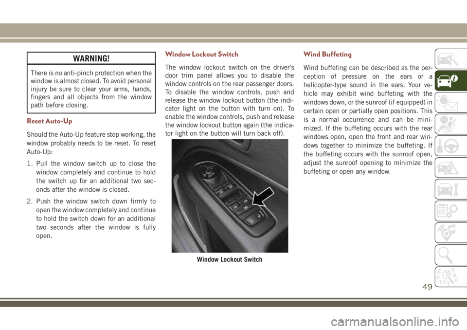
Window Lockout Switch
The window lockout switch on the driver's
door trim panel allows you to disable the
window controls on the rear passenger doors.
To disable the window controls, push and
release the window lockout button (the indi-
cator light on the button with turn on). To
enable the window controls, push and release
the window lockout button again (the indica-
tor light on the button will turn back off).
Wind Buffeting
Wind buffeting can be described as the per-
ception of pressure on the ears or a
helicopter-type sound in the ears. Your ve-
hicle may exhibit wind buffeting with the
windows down, or the sunroof (if equipped) in
certain open or partially open positions. This
is a normal occurrence and can be mini-
mized. If the buffeting occurs with the rear
windows open, open the front and rear win-
dows together to minimize the buffeting. If
the buffeting occurs with the sunroof open,
adjust the sunroof opening to minimize the
buffeting or open any window.
Window Lockout Switch
49
Page 57 of 348
chime will be audible. Refer to “Uconnect
Settings” in “Multimedia” in your Owner’s
Manual) for further information.
NOTE:
• Before closing the liftgate, make sure to be
in possession of the key because the lift-
gate may be locked.
• Use the interior door lock/unlock button on
the door panel or the key fob to lock and
unlock the liftgate. The manual door locks
on the doors and the exterior door lock
cylinder will not lock and unlock the
liftgate.
Lock The Vehicle
WARNING!
During power operation, personal injury or
cargo damage may occur. Ensure the lift-
gate travel path is clear. Make sure the
liftgate is closed and latched before driv-
ing away.NOTE:
• The liftgate will not power open or close if
the gear selector is in gear or the vehicle
speed is above 0 mph (0 km/h).
• If anything obstructs the power liftgate
while it is closing or opening, the liftgate
will automatically reverse to the closed or
open position, provided it meets sufficient
resistance.
• There are pinch sensors attached to the
side of the liftgate opening. Light pressure
anywhere along these strips will cause the
liftgate to return to the open position.
• If the power liftgate encounters multiple
obstructions within the same cycle, the
system will automatically stop. If this oc-
curs, the liftgate must be opened or closed
manually.
• The power liftgate will not operate in tem-
peratures below −22° F (−30° C) or tem-
peratures about 150° F (65° C). Be sure to
remove any buildup of snow or ice from the
liftgate before pushing any of the power
liftgate switches.• If the liftgate is left open for an extended
period of time, the liftgate may need to be
closed manually to reset power liftgate
functionality.
• Gas props support the liftgate in the open
position. However, because the gas pres-
sure drops with temperature, it may be
necessary to assist the props when opening
the liftgate in cold weather.
• Before driving off, check the instrument
cluster for a liftgate or door open message
or warning indicator. Failure to do this
could result in unintentionally leaving the
liftgate open while driving.
• If your liftgate is power closing and you put
the vehicle in gear, the liftgate will continue
to power close. However, vehicle movement
may result in a detection of an obstruction.
• If the electronic liftgate release handle is
pushed with the power liftgate is opening,
the liftgate motor will disengage to allow
manual operation.
• If the electronic liftgate release handle is
pushed while the power liftgate is closing,
the liftgate will reverse to the full open
position.
55
Page 59 of 348
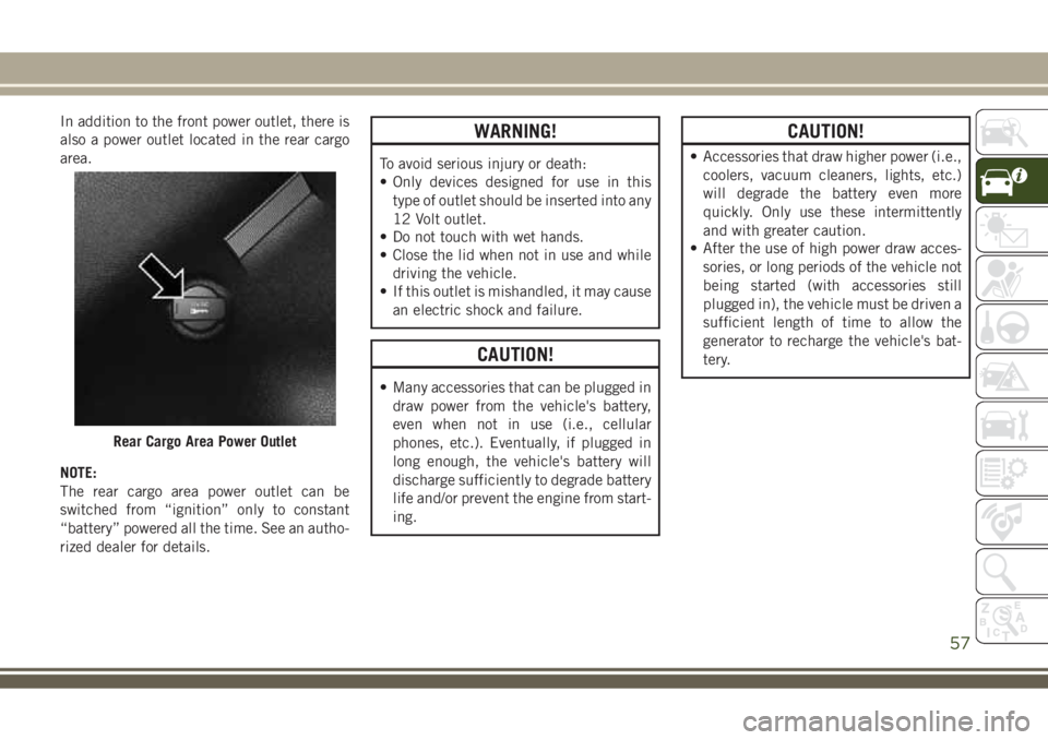
In addition to the front power outlet, there is
also a power outlet located in the rear cargo
area.
NOTE:
The rear cargo area power outlet can be
switched from “ignition” only to constant
“battery” powered all the time. See an autho-
rized dealer for details.WARNING!
To avoid serious injury or death:
• Only devices designed for use in this
type of outlet should be inserted into any
12 Volt outlet.
• Do not touch with wet hands.
• Close the lid when not in use and while
driving the vehicle.
• If this outlet is mishandled, it may cause
an electric shock and failure.
CAUTION!
• Many accessories that can be plugged in
draw power from the vehicle's battery,
even when not in use (i.e., cellular
phones, etc.). Eventually, if plugged in
long enough, the vehicle's battery will
discharge sufficiently to degrade battery
life and/or prevent the engine from start-
ing.
CAUTION!
• Accessories that draw higher power (i.e.,
coolers, vacuum cleaners, lights, etc.)
will degrade the battery even more
quickly. Only use these intermittently
and with greater caution.
• After the use of high power draw acces-
sories, or long periods of the vehicle not
being started (with accessories still
plugged in), the vehicle must be driven a
sufficient length of time to allow the
generator to recharge the vehicle's bat-
tery.
Rear Cargo Area Power Outlet
57
Page 61 of 348
GETTING TO KNOW YOUR INSTRUMENT PANEL
INSTRUMENT CLUSTER DIS-
PLAY .....................60
Instrument Cluster Display Location And
Controls.....................60
TRIP COMPUTER.............61
WARNING LIGHTS AND MES-
SAGES.....................61
Red Warning Lights..............61
Yellow Warning Lights............64
Yellow Indicator Lights............68
Green Indicator Lights............69
White Indicator Lights............70
Blue Indicator Lights.............71
Gray Indicator Lights.............71ONBOARD DIAGNOSTIC SYSTEM —
OBDII.....................71
Onboard Diagnostic System (OBD II)
Cybersecurity.................71
EMISSIONS INSPECTION AND
MAINTENANCE PROGRAMS....72
GETTING TO KNOW YOUR INSTRUMENT PANEL
59
Page 63 of 348
•Down Arrow Button
Push and release thedownarrow button to
scroll downward through the main menu
and submenus.
•Right Arrow Button
Push and release therightarrow button to
access the information screens or submenu
screens of a main menu item.
•Left Arrow Button
Push and release theleftarrow button to
access the information screens or submenu
screens of a main menu item.
•OK Button
Push theOKbutton to access/select the
information screens or submenu screens of
a main menu item. Push and hold theOK
button for one second to reset displayed/
selected features that can be reset.
TRIP COMPUTER
Push and release the up or down arrow button
until the Trip A or Trip B icon is highlighted in
the instrument cluster display (Toggle left or
right to select Trip A or Trip B). Push and
release the OK button to display the Trip
information.
WARNING LIGHTS AND
MESSAGES
The warning/indicator lights will illuminate in
the instrument panel together with a dedi-
cated message and/or acoustic signal when
applicable. These indications are indicative
and precautionary and as such must not be
considered as exhaustive and/or alternative
to the information contained in the Owner’s
Manual, which you are advised to read care-
fully in all cases. Always refer to the informa-
tion in this chapter in the event of a failure
indication. All active telltales will display first
if applicable. The system check menu may
appear different based upon equipment op-
tions and current vehicle status. Some tell-
tales are optional and may not appear.
Red Warning Lights
— Air Bag Warning Light
This light indicates a fault with the air bag,
and will turn on for four to eight seconds as a
bulb check when the ignition is placed in the
ON/RUN or ACC/ON/RUN position. This light
will illuminate with a single chime when afault with the air bag has been detected, it
will stay on until the fault is cleared. If the
light is either not on during startup, stays on,
or turns on while driving, have the system
inspected at an authorized dealer as soon as
possible.
— Brake Warning Light
This light monitors various brake functions,
including brake fluid level and parking brake
application. If the brake light turns on it may
indicate that the parking brake is applied,
that the brake fluid level is low, or that there
is a problem with the anti-lock brake system.
If the light remains on when the parking
brake has been disengaged, and the fluid
level is at the full mark on the master cylinder
reservoir, it indicates a possible brake hy-
draulic system malfunction or that a problem
with the Brake Booster has been detected by
the Anti-Lock Brake System (ABS) / Elec-
tronic Stability Control (ESC) system. In this
case, the light will remain on until the condi-
tion has been corrected. If the problem is
related to the brake booster, the ABS pump
will run when applying the brake, and a brake
pedal pulsation may be felt during each stop.
61