key JEEP COMPASS 2018 Owner handbook (in English)
[x] Cancel search | Manufacturer: JEEP, Model Year: 2018, Model line: COMPASS, Model: JEEP COMPASS 2018Pages: 348, PDF Size: 6.03 MB
Page 56 of 348
LIFTGATE
Opening
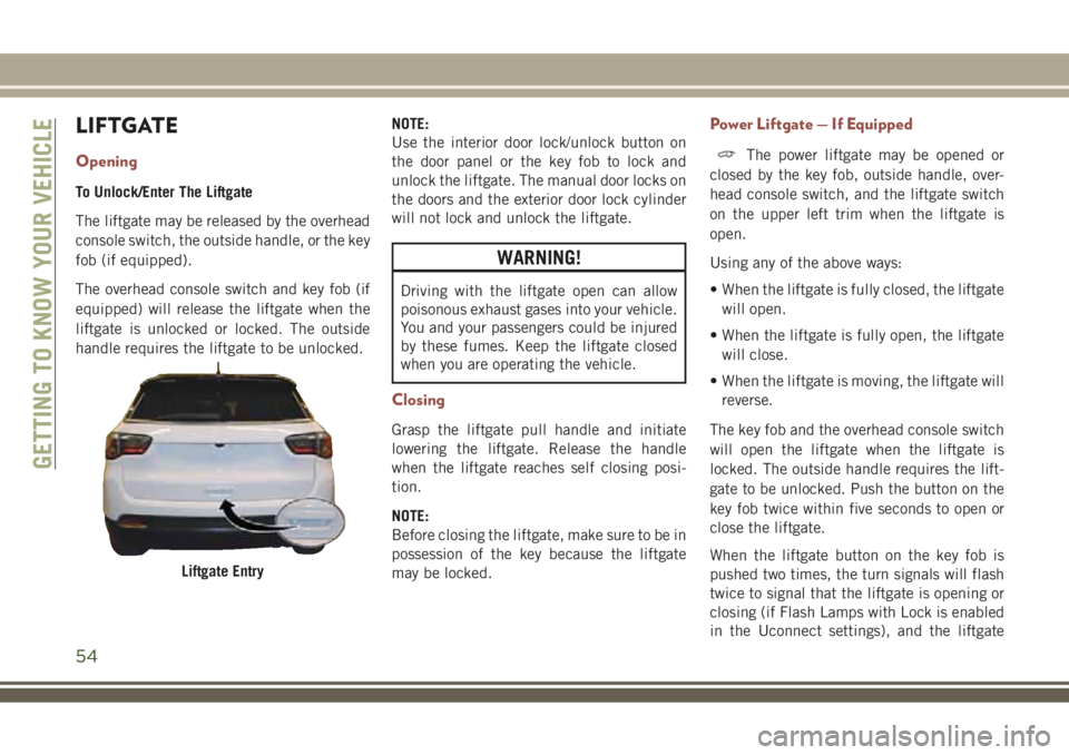
To Unlock/Enter The Liftgate
The liftgate may be released by the overhead
console switch, the outside handle, or the key
fob (if equipped).
The overhead console switch and key fob (if
equipped) will release the liftgate when the
liftgate is unlocked or locked. The outside
handle requires the liftgate to be unlocked.NOTE:
Use the interior door lock/unlock button on
the door panel or the key fob to lock and
unlock the liftgate. The manual door locks on
the doors and the exterior door lock cylinder
will not lock and unlock the liftgate.
WARNING!
Driving with the liftgate open can allow
poisonous exhaust gases into your vehicle.
You and your passengers could be injured
by these fumes. Keep the liftgate closed
when you are operating the vehicle.
Closing
Grasp the liftgate pull handle and initiate
lowering the liftgate. Release the handle
when the liftgate reaches self closing posi-
tion.
NOTE:
Before closing the liftgate, make sure to be in
possession of the key because the liftgate
may be locked.
Power Liftgate — If Equipped
The power liftgate may be opened or
closed by the key fob, outside handle, over-
head console switch, and the liftgate switch
on the upper left trim when the liftgate is
open.
Using any of the above ways:
• When the liftgate is fully closed, the liftgate
will open.
• When the liftgate is fully open, the liftgate
will close.
• When the liftgate is moving, the liftgate will
reverse.
The key fob and the overhead console switch
will open the liftgate when the liftgate is
locked. The outside handle requires the lift-
gate to be unlocked. Push the button on the
key fob twice within five seconds to open or
close the liftgate.
When the liftgate button on the key fob is
pushed two times, the turn signals will flash
twice to signal that the liftgate is opening or
closing (if Flash Lamps with Lock is enabled
in the Uconnect settings), and the liftgate
Liftgate Entry
GETTING TO KNOW YOUR VEHICLE
54
Page 57 of 348
chime will be audible. Refer to “Uconnect
Settings” in “Multimedia” in your Owner’s
Manual) for further information.
NOTE:
• Before closing the liftgate, make sure to be
in possession of the key because the lift-
gate may be locked.
• Use the interior door lock/unlock button on
the door panel or the key fob to lock and
unlock the liftgate. The manual door locks
on the doors and the exterior door lock
cylinder will not lock and unlock the
liftgate.
Lock The Vehicle
WARNING!
During power operation, personal injury or
cargo damage may occur. Ensure the lift-
gate travel path is clear. Make sure the
liftgate is closed and latched before driv-
ing away.NOTE:
• The liftgate will not power open or close if
the gear selector is in gear or the vehicle
speed is above 0 mph (0 km/h).
• If anything obstructs the power liftgate
while it is closing or opening, the liftgate
will automatically reverse to the closed or
open position, provided it meets sufficient
resistance.
• There are pinch sensors attached to the
side of the liftgate opening. Light pressure
anywhere along these strips will cause the
liftgate to return to the open position.
• If the power liftgate encounters multiple
obstructions within the same cycle, the
system will automatically stop. If this oc-
curs, the liftgate must be opened or closed
manually.
• The power liftgate will not operate in tem-
peratures below −22° F (−30° C) or tem-
peratures about 150° F (65° C). Be sure to
remove any buildup of snow or ice from the
liftgate before pushing any of the power
liftgate switches.• If the liftgate is left open for an extended
period of time, the liftgate may need to be
closed manually to reset power liftgate
functionality.
• Gas props support the liftgate in the open
position. However, because the gas pres-
sure drops with temperature, it may be
necessary to assist the props when opening
the liftgate in cold weather.
• Before driving off, check the instrument
cluster for a liftgate or door open message
or warning indicator. Failure to do this
could result in unintentionally leaving the
liftgate open while driving.
• If your liftgate is power closing and you put
the vehicle in gear, the liftgate will continue
to power close. However, vehicle movement
may result in a detection of an obstruction.
• If the electronic liftgate release handle is
pushed with the power liftgate is opening,
the liftgate motor will disengage to allow
manual operation.
• If the electronic liftgate release handle is
pushed while the power liftgate is closing,
the liftgate will reverse to the full open
position.
55
Page 58 of 348
WARNING!
• Driving with the liftgate open can allow
poisonous exhaust gases into your ve-
hicle. You and your passengers could be
injured by these fumes. Keep the liftgate
closed when you are operating the ve-
hicle.
• If you are required to drive with the
liftgate open, make sure that all win-
dows are closed, and the climate control
blower switch is set at high speed. Do
not use the recirculation mode.
NOTE:
Allow the power system to open the liftgate.
Manually pushing or pulling the liftgate may
activate the liftgate obstacle detection fea-
ture and stop the power operation or reverse
its direction.
WARNING!
Personal injury or cargo damage may occur
if caught in the path of the liftgate. Make
sure the liftgate path is clear before acti-
vating the liftgate.
INTERNAL EQUIPMENT
Power Outlets
Your vehicle is equipped with 12 Volt
(13 Amp) power outlets that can be used to
power cellular phones, small electronics and
other low powered electrical accessories. The
power outlets are labeled with either a “key”
or a “battery” symbol to indicate how the
outlet is powered. Power outlets labeled with
a “key” are powered when the ignition is in
the ON or ACC position, while the outlets
labeled with a “battery” are connected di-
rectly to the battery and powered at all times.
NOTE:
• All accessories connected to the “battery”
powered outlets should be removed or
turned off when the vehicle is not in use to
protect the battery against discharge.
CAUTION!
Power outlets are designed for accessory
plugs only. Do not insert any other object
in the power outlets as this will damage
the outlet and blow the fuse. Improper use
CAUTION!
of the power outlet can cause damage not
covered by your New Vehicle Limited War-
ranty.
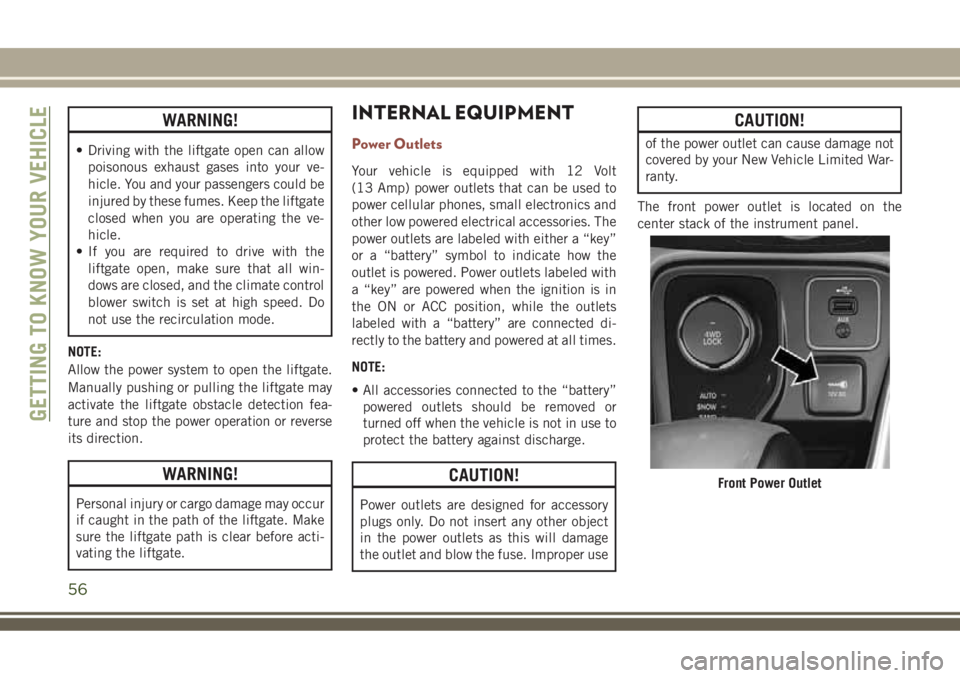
The front power outlet is located on the
center stack of the instrument panel.
Front Power Outlet
GETTING TO KNOW YOUR VEHICLE
56
Page 91 of 348
Forward Collision Warning (FCW) With
Mitigation — If Equipped
Forward Collision Warning (FCW) With Miti-
gation Operation
The Forward Collision Warning (FCW) system
with mitigation provides the driver with au-
dible warnings, visual warnings (within the
instrument cluster display), and may apply a
brake jerk to warn the driver when it detects a
potential frontal collision. The warnings and
limited braking are intended to provide the
driver with enough time to react, avoid or
mitigate the potential collision.
NOTE:
FCW monitors the information from the for-
ward looking sensors as well as the Electronic
Brake Controller (EBC), to calculate the prob-
ability of a forward collision. When the sys-
tem determines that a forward collision is
probable, the driver will be provided with
audible and visual warnings and may provide
a brake jerk warning.
If the driver does not take action based upon
these progressive warnings, then the system
will provide a limited level of active braking tohelp slow the vehicle and mitigate the poten-
tial forward collision. If the driver reacts to
the warnings by braking and the system de-
termines that the driver intends to avoid the
collision by braking but has not applied suf-
ficient brake force, the system will compen-
sate and provide additional brake force as
required.
If a Forward Collision Warning with Mitigation
event begins at a speed below 26 mph
(42 km/h), the system may provide the maxi-
mum braking possible to mitigate the poten-
tial forward collision. If the Forward Collision
Warning with Mitigation event stops the ve-
hicle completely, the system will hold the
vehicle at standstill for two seconds and then
release the brakes.
When the system determines a collision with
the vehicle in front of you is no longer prob-
able, the warning message will be deacti-
vated.
NOTE:
• The minimum speed for FCW activation is
1 mph (2 km/h).• The FCW alerts may be triggered on objects
other than vehicles such as guard rails or
sign posts based on the course prediction.
This is expected and is a part of normal
FCW activation and functionality.
• It is unsafe to test the FCW system. To
prevent such misuse of the system, after
four Active Braking events within a key
cycle, the Active Braking portion of FCW
will be deactivated until the next key cycle.
• The FCW system is intended for on-road use
only. If the vehicle is taken off-road, the
FCW system should be deactivated to pre-
vent unnecessary warnings to the
surroundings.
WARNING!
Forward Collision Warning (FCW) is not
intended to avoid a collision on its own,
nor can FCW detect every type of potential
collision. The driver has the responsibility
to avoid a collision by controlling the ve-
hicle via braking and steering. Failure to
follow this warning could lead to serious
injury or death.
89
Page 97 of 348
Low" message and a graphic showing the
pressure values of each tire with the low tire
pressure values highlighted or in a different
color.
Should this occur, you should stop as soon as
possible and inflate the tires with low pres-
sure (those highlighted or in a different color
in the instrument cluster display graphic) to
the vehicle’s recommended cold placard
pressure value. Once the system receives the
updated tire pressures, the system will auto-
matically update, the pressure values in the
graphic display in the instrument cluster will
stop being highlighted or return to their origi-
nal color, and the “Tire Pressure Monitoring
Telltale Light” will turn off.
NOTE:
When filling warm tires, the tire pressure may
need to be increased up to an additional 4 psi
(30 kPa) above the recommended cold plac-
ard pressure in order to turn the Tire Pressure
Monitoring Telltale Light off. The vehicle may
need to be driven for up to 10 minutes above
15 mph (24 km/h) in order for the TPMS to
receive this information.SERVICE TPMS Warning
When a system fault is detected, the “Tire
Pressure Monitoring Telltale Light” will flash
on and off for 75 seconds and then remain on
solid. The system fault will also sound a
chime. In addition, the instrument cluster
will display a "SERVICE TPM SYSTEM" mes-
sage for a minimum of five seconds and then
display dashes (- -) in place of the pressure
value to indicate which sensor is not being
received.
If the ignition key is cycled, this sequence
will repeat, providing the system fault still
exists. If the system fault no longer exists, the
“Tire Pressure Monitoring Telltale Light” will
no longer flash, and the “SERVICE TPM SYS-
TEM” message will no longer display, and a
pressure value will display in place of the
dashes. A system fault can occur due to any
of the following:
• Jamming due to electronic devices or driv-
ing next to facilities emitting the same
radio frequencies as the TPMS sensors.
• Installing some form of aftermarket window
tinting that affects radio wave signals.• Lots of snow or ice around the wheels or
wheel housings.
• Using tire chains on the vehicle.
• Using wheels/tires not equipped with TPMS
sensors.
Vehicles With Compact Spare or Non-Matching
Full Size Spare
1. The compact spare tire or non-matching
full size does not have a tire pressure
monitoring sensor. Therefore, the TPMS
will not monitor the pressure in the com-
pact spare tire.
2. If you install the compact or non-
matching full size spare tire in place of a
road tire that has a pressure below the
low-pressure warning limit, upon the next
ignition key cycle, the “TPMS Telltale
Light” will remain on and a chime will
sound. In addition, the graphic in the
instrument cluster will still display a dif-
ferent color or highlighted pressure value.
95
Page 98 of 348
3. After driving the vehicle for up to 10 min-
utes above 15 mph (24 km/h), the “TPMS
Telltale Light” will flash on and off for
75 seconds and then remain on solid. In
addition, the instrument cluster will dis-
play a “SERVICE TPM SYSTEM” message
for five seconds and then display dashes
(- -) in place of the pressure value.
4. For each subsequent ignition key cycle, a
chime will sound, the “TPMS Telltale
Light” will flash on and off for 75 seconds
and then remain on solid, and the instru-
ment cluster will display a “SERVICE
TPM SYSTEM” message for five seconds
and then display dashes (- -) in place of
the pressure value.
5. Once you repair or replace the original
road tire and reinstall it on the vehicle in
place of the compact spare, the TPMS will
update automatically. In addition, the
“TPMS Telltale Light” will turn off and the
graphic in the instrument cluster will dis-play a new pressure value instead of
dashes (- -), as long as no tire pressure is
below the low-pressure warning limit in
any of the four active road tires. The
vehicle may need to be driven for up to
10 minutes above 15 mph (24 km/h) in
order for the TPMS to receive this
information.
TPMS Deactivation — If Equipped
The TPMS can be deactivated if replacing all
four wheel and tire assemblies (road tires)
with wheel and tire assemblies that do not
have TPMS Sensors, such as when installing
winter wheel and tire assemblies on your
vehicle.
To deactivate the TPMS, first replace all four
wheel and tire assemblies (road tires) with
tires not equipped with Tire Pressure Moni-
toring (TPM) Sensors. Then, drive the vehicle
for 10 minutes above 15 mph (24 km/h). The
TPMS will chime, the "TPM Telltale Light"
will flash on and off for 75 seconds and thenremain on. The instrument cluster will dis-
play the “SERVICE TPM SYSTEM” message
and then display dashes (--) in place of the
pressure values.
Beginning with the next ignition cycle, the
TPMS will no longer chime or display the
“SERVICE TPM SYSTEM” message in the
instrument cluster but dashes (--) will remain
in place of the pressure values.
To reactivate the TPMS, replace all four
wheel and tire assemblies (road tires) with
tires equipped with TPM sensors. Then, drive
the vehicle for up to 10 minutes above
15 mph (24 km/h). The TPMS will chime, the
"TPM Telltale Light" will flash on and off for
75 seconds and then turn off. The instrument
cluster will display the “SERVICE TPM SYS-
TEM” message and then display pressure
values in place of the dashes. On the next
ignition cycle the "SERVICE TPM SYSTEM"
message will no longer be displayed as long
as no system fault exists.
SAFETY
96
Page 126 of 348
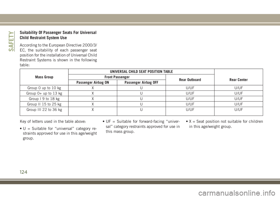
Suitability Of Passenger Seats For Universal
Child Restraint System Use
According to the European Directive 2000/3/
EC, the suitability of each passenger seat
position for the installation of Universal Child
Restraint Systems is shown in the following
table:
Mass GroupUNIVERSAL CHILD SEAT POSITION TABLE
Front Passenger
Rear Outboard Rear Center
Passenger Airbag ON Passenger Airbag OFF
Group 0 up to 10 kg X U U/UF U/UF
Group 0+ up to 13 kg X U U/UF U/UF
GroupI9to18kg X UU/UF U/UF
Group II 15 to 25 kg X U U/UF U/UF
Group III 22 to 36 kg X U U/UF U/UF
Key of letters used in the table above:
• U = Suitable for “universal” category re-
straints approved for use in this age/weight
group.• UF = Suitable for forward-facing “univer-
sal” category restraints approved for use in
this mass group.• X = Seat position not suitable for children
in this age/weight group.
SAFETY
124
Page 131 of 348
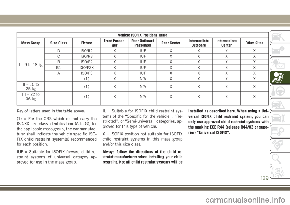
Vehicle ISOFIX Positions Table
Mass Group Size Class FixtureFront Passen-
gerRear Outboard
PassengerRear CenterIntermediate
OutboardIntermediate
CenterOther Sites
I–9to18kgD ISO/R2 X IUF X X X X
C ISO/R3 X IUF X X X X
B ISO/F2 X IUF X X X X
B1 ISO/F2X X IUF X X X X
A ISO/F3 X IUF X X X X
(1)XN/AXXXX
II–15to
25 kg(1)XN/AXXXX
III–22to
36 kg(1)XN/AXXXX
Key of letters used in the table above:
(1) = For the CRS which do not carry the
ISO/XX size class identification (A to G), for
the applicable mass group, the car manufac-
turer shall indicate the vehicle specific ISO-
FIX child restraint system(s) recommended
for each position.
IUF = Suitable for ISOFIX forward child re-
straint systems of universal category ap-
proved for use in the mass group.IL = Suitable for ISOFIX child restraint sys-
tems of the “Specific for the vehicle”, “Re-
stricted”, or “Semi-universal” categories, ap-
proved for this type of vehicle.
X = ISOFIX position not suitable for ISOFIX
child restraint systems in this mass group
and/or this size class.
Always follow the directions of the child re-
straint manufacturer when installing your child
restraint. Not all child restraint systems will beinstalled as described here. When using a Uni-
versal ISOFIX child restraint system, you can
only use approved child restraint systems with
the marking ECE R44 (release R44/03 or supe-
rior) “Universal ISOFIX”.
129
Page 134 of 348
The following table, according to
European standard ECE 129, in-
dicates the possibility of i-Size
child restraint system installa-
tion.i-Size Child Seat Position Table
DeviceFront
Passen-
gerRear
Out-
boardRear
Center
i-Size
Child
Re-
straint
Sys-
temsISO/R2 X i-U X
ISO/F2 X i-U X
Key of letters used in the table above:
• i-U = Suitable for Universal i-Size child
restraint systems, both rearward facing and
forward facing.• X = Seat not suitable for Universal i-Size
child restraint systems.
Child Restraint Systems Recommended By
FCA For Your Vehicle
Lineaccessori MOPAR includes a complete
range of child restraint systems to be fixed
using the seat belt with three anchorage
points or the ISOFIX anchorages.
Figure XXSAFETY
132
Page 140 of 348
WARNING!
• ONLY use the driver’s side floor mat on
the driver’s side floor area. To check for
interference, with the vehicle properly
parked with the engine off, fully depress
the accelerator, the brake, and the
clutch pedal (if present) to check for
interference. If your floor mat interferes
with the operation of any pedal, or is not
secure to the floor, remove the floor mat
from the vehicle and place the floor mat
in your trunk.
• ONLY use the passenger’s side floor mat
on the passenger’s side floor area.
• ALWAYS make sure objects cannot fall or
slide into the driver’s side floor area
when the vehicle is moving. Objects can
become trapped under accelerator,
brake, or clutch pedals and could cause
a loss of vehicle control.
• NEVER place any objects under the floor
mat (e.g., towels, keys, etc.). These ob-
jects could change the position of the
floor mat and may cause interference
WARNING!
with the accelerator, brake, or clutch
pedals.
• If the vehicle carpet has been removed
and re-installed, always properly attach
carpet to the floor and check the floor
mat fasteners are secure to the vehicle
carpet. Fully depress each pedal to
check for interference with the accelera-
tor, brake, or clutch pedals then re-
install the floor mats.
• It is recommended to only use mild soap
and water to clean your floor mats. After
cleaning, always check your floor mat
has been properly installed and is se-
cured to your vehicle using the floor mat
fasteners by lightly pulling mat.
Periodic Safety Checks You Should Make
Outside The Vehicle
Tires
Examine tires for excessive tread wear and
uneven wear patterns. Check for stones,
nails, glass, or other objects lodged in thetread or sidewall. Inspect the tread for cuts
and cracks. Inspect sidewalls for cuts,
cracks, and bulges. Check the wheel nuts for
tightness. Check the tires (including spare)
for proper cold inflation pressure.
Lights
Have someone observe the operation of brake
lights and exterior lights while you work the
controls. Check turn signal and high beam
indicator lights on the instrument panel.
Door Latches
Check for proper closing, latching, and lock-
ing.
Fluid Leaks
Check area under the vehicle after overnight
parking for fuel, coolant, oil, or other fluid
leaks. Also, if gasoline fumes are detected or
if fuel, or brake fluid leaks are suspected. The
cause should be located and corrected imme-
diately.
SAFETY
138