tow JEEP COMPASS 2018 Owner handbook (in English)
[x] Cancel search | Manufacturer: JEEP, Model Year: 2018, Model line: COMPASS, Model: JEEP COMPASS 2018Pages: 348, PDF Size: 6.03 MB
Page 23 of 348
Security System Manual Override
The vehicle security alarm will not arm if you
lock the doors using the manual door lock
plunger.
PREMIUM VEHICLE
SECURITY ALARM — IF
EQUIPPED
The premium vehicle security alarm system
monitors the doors, hood latch, and liftgate
for unauthorized entry and the ignition switch
for unauthorized operation. The system also
includes a dual function intrusion sensor and
vehicle tilt sensor. The intrusion sensor moni-
tors the vehicle interior for motion. The ve-
hicle tilt sensor monitors the vehicle for any
tilting actions (tow away, tire removal, ferry
transport, etc). A siren with battery backup
which senses interruptions of power and
communications is also included.
If a perimeter violation triggers the security
system, the siren will sound for 29 seconds
and the exterior lights will flash followed byapproximately five seconds of no activity.
This will continue for eight cycles if no action
is taken to disarm the system.
To Arm The System
Follow these steps to arm the security alarm:
1. Remove the key from the ignition system,
refer to "Starting The Engine" in "Starting
And Operating" in your Owner’s manual
for further information.
• For vehicles equipped with Keyless
Enter-N-Go — Passive Entry, make
sure the vehicle ignition system is
"OFF."
• For vehicles not equipped with Keyless
Enter-N-Go — Passive Entry, make
sure the vehicle ignition system is
"OFF" and the key is physically re-
moved from the ignition.
2. Perform one of the following methods to
lock the vehicle:
• Push lock on the interior power door
lock switch with the driver and/or pas-
senger door open.• Push the lock button on the exterior
passive entry door handle with a key
fob available in the same exterior zone,
refer to "Doors" in "Getting To Know
Your Vehicle" in your Owner’s Manua
for further information.
• Push the lock button on the key fob.
3. If any doors are open, close them.
NOTE:
• Once the security system is armed, it re-
mains in that state until you disarm it by
following either of the disarming proce-
dures described. If a power loss occurs
after arming the system, you must disarm
the system after restoring power to prevent
alarm activation.
• The ultrasonic intrusion sensor (motion de-
tector) actively monitors your vehicle every
time you arm the security system. If you
prefer, you can turn off the ultrasonic intru-
sion sensor when arming the security sys-
tem. To do so, push the lock button on the
key fob five times within five seconds of
arming the system (while the Vehicle Secu-
rity Light is flashing rapidly).
21
Page 33 of 348
Front Head Restraint Adjustment
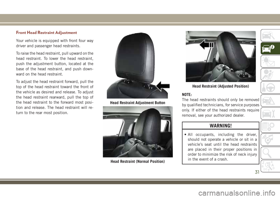
Your vehicle is equipped with front four way
driver and passenger head restraints.
To raise the head restraint, pull upward on the
head restraint. To lower the head restraint,
push the adjustment button, located at the
base of the head restraint, and push down-
ward on the head restraint.
To adjust the head restraint forward, pull the
top of the head restraint toward the front of
the vehicle as desired and release. To adjust
the head restraint rearward, pull the top of
the head restraint to the forward most posi-
tion and release. The head restraint will re-
turn to the rear most position.NOTE:
The head restraints should only be removed
by qualified technicians, for service purposes
only. If either of the head restraints require
removal, see your authorized dealer.
WARNING!
• All occupants, including the driver,
should not operate a vehicle or sit in a
vehicle’s seat until the head restraints
are placed in their proper positions in
order to minimize the risk of neck injury
in the event of a crash.
Head Restraint Adjustment Button
Head Restraint (Normal Position)
Head Restraint (Adjusted Position)
31
Page 35 of 348
STEERING WHEEL
Tilt/Telescoping Steering Column
This feature allows you to tilt the steering
column upward or downward. It also allows
you to lengthen or shorten the steering col-
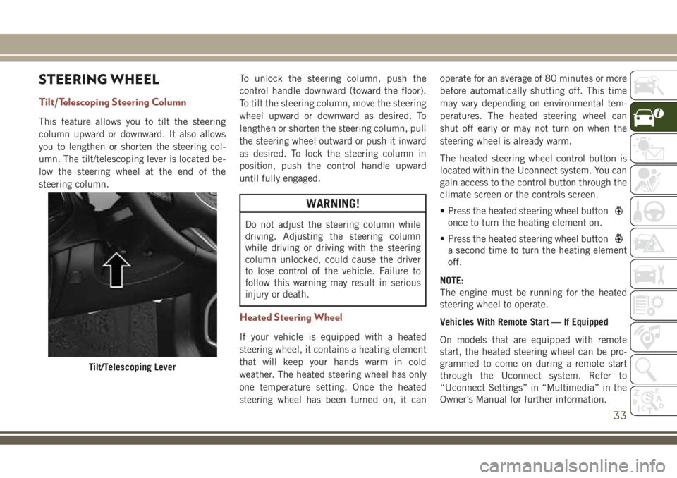
umn. The tilt/telescoping lever is located be-
low the steering wheel at the end of the
steering column.To unlock the steering column, push the
control handle downward (toward the floor).
To tilt the steering column, move the steering
wheel upward or downward as desired. To
lengthen or shorten the steering column, pull
the steering wheel outward or push it inward
as desired. To lock the steering column in
position, push the control handle upward
until fully engaged.
WARNING!
Do not adjust the steering column while
driving. Adjusting the steering column
while driving or driving with the steering
column unlocked, could cause the driver
to lose control of the vehicle. Failure to
follow this warning may result in serious
injury or death.
Heated Steering Wheel
If your vehicle is equipped with a heated
steering wheel, it contains a heating element
that will keep your hands warm in cold
weather. The heated steering wheel has only
one temperature setting. Once the heated
steering wheel has been turned on, it canoperate for an average of 80 minutes or more
before automatically shutting off. This time
may vary depending on environmental tem-
peratures. The heated steering wheel can
shut off early or may not turn on when the
steering wheel is already warm.
The heated steering wheel control button is
located within the Uconnect system. You can
gain access to the control button through the
climate screen or the controls screen.
• Press the heated steering wheel button
once to turn the heating element on.
• Press the heated steering wheel button
a second time to turn the heating element
off.
NOTE:
The engine must be running for the heated
steering wheel to operate.
Vehicles With Remote Start — If Equipped
On models that are equipped with remote
start, the heated steering wheel can be pro-
grammed to come on during a remote start
through the Uconnect system. Refer to
“Uconnect Settings” in “Multimedia” in the
Owner’s Manual for further information.
Tilt/Telescoping Lever
33
Page 37 of 348
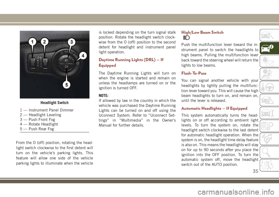
From the O (off) position, rotating the head-
light switch clockwise to the first detent will
turn on the vehicle’s parking lights. This
feature will allow one side of the vehicle
parking lights to illuminate when the vehicleis locked depending on the turn signal stalk
position. Rotate the headlight switch clock-
wise from the O (off) position to the second
detent for headlight and instrument panel
light operation.
Daytime Running Lights (DRL) — If
Equipped
The Daytime Running Lights will turn on
when the engine is started and remain on
unless the headlamps are turned on or the
ignition is turned OFF.
NOTE:
If allowed by law in the country in which the
vehicle was purchased the Daytime Running
Lights can be turned on and off using the
Uconnect System. Refer to “Uconnect Set-
tings” in “Multimedia” in the Owner’s
Manual for further details.
High/Low Beam Switch
Push the multifunction lever toward the in-
strument panel to switch the headlights to
high beams. Pulling the multifunction lever
back toward the steering wheel will return the
lights to low beams.
Flash-To-Pass
You can signal another vehicle with your
headlights by lightly pulling the multifunc-
tion lever toward you. This will cause the high
beam headlights to turn on, and remain on,
until the lever is released.
Automatic Headlights — If Equipped
This system automatically turns the head-
lights on or off according to ambient light
levels. To turn the system on, rotate the
headlight switch clockwise to the last detent
for automatic headlight operation. When the
system is on, the headlight time delay feature
is also on. This means the headlights will stay
on for up to 90 seconds after you place the
ignition into the OFF position. To turn the
automatic system off, move the headlight
switch out of the AUTO position.
Headlight Switch
1 — Instrument Panel Dimmer
2 — Headlight Leveling
3 — Push Front Fog
4 — Rotate Headlight
5 — Push Rear Fog
35
Page 40 of 348
Front Wipers
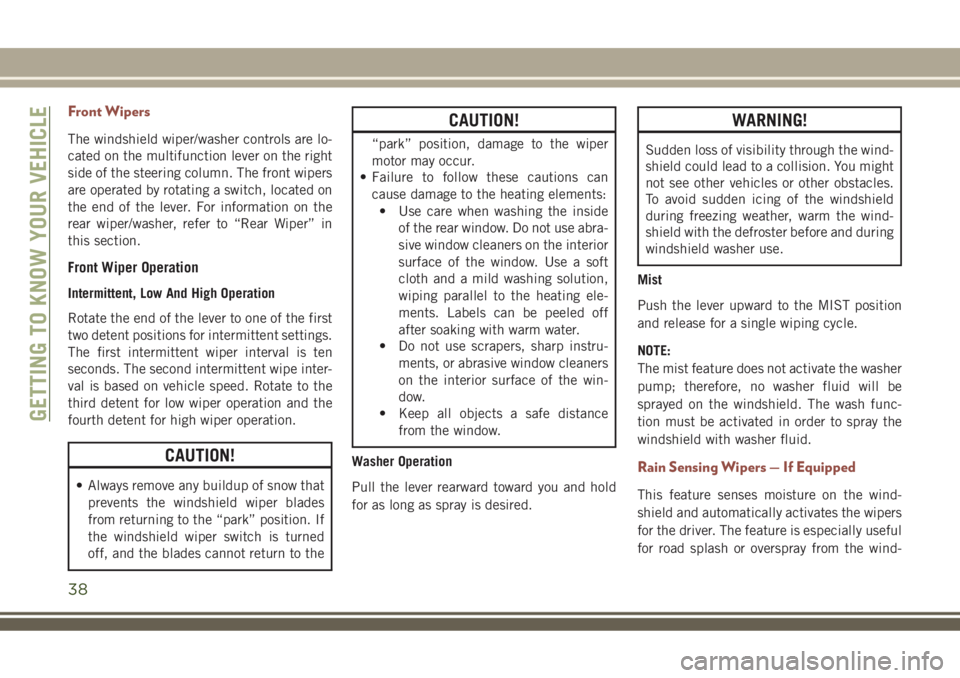
The windshield wiper/washer controls are lo-
cated on the multifunction lever on the right
side of the steering column. The front wipers
are operated by rotating a switch, located on
the end of the lever. For information on the
rear wiper/washer, refer to “Rear Wiper” in
this section.
Front Wiper Operation
Intermittent, Low And High Operation
Rotate the end of the lever to one of the first
two detent positions for intermittent settings.
The first intermittent wiper interval is ten
seconds. The second intermittent wipe inter-
val is based on vehicle speed. Rotate to the
third detent for low wiper operation and the
fourth detent for high wiper operation.
CAUTION!
• Always remove any buildup of snow that
prevents the windshield wiper blades
from returning to the “park” position. If
the windshield wiper switch is turned
off, and the blades cannot return to the
CAUTION!
“park” position, damage to the wiper
motor may occur.
• Failure to follow these cautions can
cause damage to the heating elements:
• Use care when washing the inside
of the rear window. Do not use abra-
sive window cleaners on the interior
surface of the window. Use a soft
cloth and a mild washing solution,
wiping parallel to the heating ele-
ments. Labels can be peeled off
after soaking with warm water.
• Do not use scrapers, sharp instru-
ments, or abrasive window cleaners
on the interior surface of the win-
dow.
• Keep all objects a safe distance
from the window.
Washer Operation
Pull the lever rearward toward you and hold
for as long as spray is desired.
WARNING!
Sudden loss of visibility through the wind-
shield could lead to a collision. You might
not see other vehicles or other obstacles.
To avoid sudden icing of the windshield
during freezing weather, warm the wind-
shield with the defroster before and during
windshield washer use.
Mist
Push the lever upward to the MIST position
and release for a single wiping cycle.
NOTE:
The mist feature does not activate the washer
pump; therefore, no washer fluid will be
sprayed on the windshield. The wash func-
tion must be activated in order to spray the
windshield with washer fluid.
Rain Sensing Wipers — If Equipped
This feature senses moisture on the wind-
shield and automatically activates the wipers
for the driver. The feature is especially useful
for road splash or overspray from the wind-
GETTING TO KNOW YOUR VEHICLE
38
Page 45 of 348
Icon Description
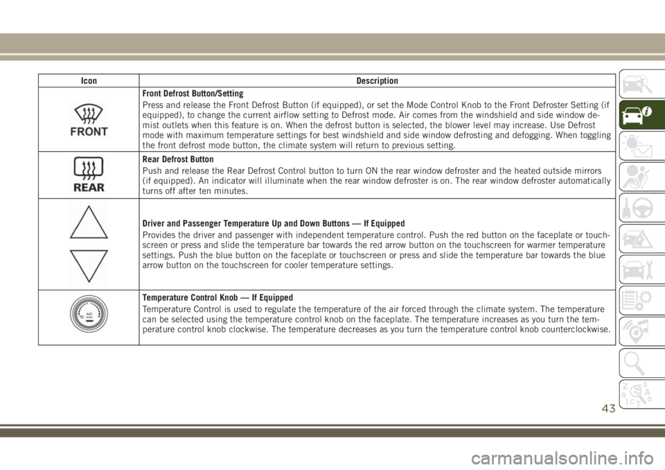
Front Defrost Button/Setting
Press and release the Front Defrost Button (if equipped), or set the Mode Control Knob to the Front Defroster Setting (if
equipped), to change the current airflow setting to Defrost mode. Air comes from the windshield and side window de-
mist outlets when this feature is on. When the defrost button is selected, the blower level may increase. Use Defrost
mode with maximum temperature settings for best windshield and side window defrosting and defogging. When toggling
the front defrost mode button, the climate system will return to previous setting.
Rear Defrost Button
Push and release the Rear Defrost Control button to turn ON the rear window defroster and the heated outside mirrors
(if equipped). An indicator will illuminate when the rear window defroster is on. The rear window defroster automatically
turns off after ten minutes.
Driver and Passenger Temperature Up and Down Buttons — If Equipped
Provides the driver and passenger with independent temperature control. Push the red button on the faceplate or touch-
screen or press and slide the temperature bar towards the red arrow button on the touchscreen for warmer temperature
settings. Push the blue button on the faceplate or touchscreen or press and slide the temperature bar towards the blue
arrow button on the touchscreen for cooler temperature settings.
Temperature Control Knob — If Equipped
Temperature Control is used to regulate the temperature of the air forced through the climate system. The temperature
can be selected using the temperature control knob on the faceplate. The temperature increases as you turn the tem-
perature control knob clockwise. The temperature decreases as you turn the temperature control knob counterclockwise.
43
Page 55 of 348
HOOD
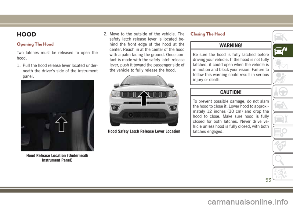
Opening The Hood
Two latches must be released to open the
hood.
1. Pull the hood release lever located under-
neath the driver’s side of the instrument
panel.2. Move to the outside of the vehicle. The
safety latch release lever is located be-
hind the front edge of the hood at the
center. Reach in at the center of the hood
with a palm facing the ground. Once con-
tact is made with the safety latch release
lever, push it toward the passenger side of
the vehicle to fully release the hood.
Closing The Hood
WARNING!
Be sure the hood is fully latched before
driving your vehicle. If the hood is not fully
latched, it could open when the vehicle is
in motion and block your vision. Failure to
follow this warning could result in serious
injury or death.
CAUTION!
To prevent possible damage, do not slam
the hood to close it. Lower hood to approxi-
mately 12 inches (30 cm) and drop the
hood to close. Make sure hood is fully
closed for both latches. Never drive ve-
hicle unless hood is fully closed, with both
latches engaged.
Hood Release Location (Underneath
Instrument Panel)
Hood Safety Latch Release Lever Location
53
Page 65 of 348
WARNING!
Continued operation with reduced assist
could pose a safety risk to yourself and
others. Service should be obtained as soon
as possible.
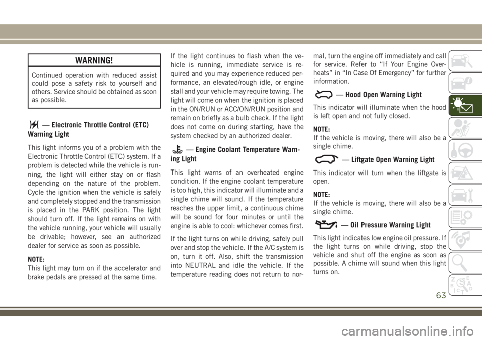
— Electronic Throttle Control (ETC)
Warning Light
This light informs you of a problem with the
Electronic Throttle Control (ETC) system. If a
problem is detected while the vehicle is run-
ning, the light will either stay on or flash
depending on the nature of the problem.
Cycle the ignition when the vehicle is safely
and completely stopped and the transmission
is placed in the PARK position. The light
should turn off. If the light remains on with
the vehicle running, your vehicle will usually
be drivable; however, see an authorized
dealer for service as soon as possible.
NOTE:
This light may turn on if the accelerator and
brake pedals are pressed at the same time.If the light continues to flash when the ve-
hicle is running, immediate service is re-
quired and you may experience reduced per-
formance, an elevated/rough idle, or engine
stall and your vehicle may require towing. The
light will come on when the ignition is placed
in the ON/RUN or ACC/ON/RUN position and
remain on briefly as a bulb check. If the light
does not come on during starting, have the
system checked by an authorized dealer.— Engine Coolant Temperature Warn-
ing Light
This light warns of an overheated engine
condition. If the engine coolant temperature
is too high, this indicator will illuminate and a
single chime will sound. If the temperature
reaches the upper limit, a continuous chime
will be sound for four minutes or until the
engine is able to cool: whichever comes first.
If the light turns on while driving, safely pull
over and stop the vehicle. If the A/C system is
on, turn it off. Also, shift the transmission
into NEUTRAL and idle the vehicle. If the
temperature reading does not return to nor-mal, turn the engine off immediately and call
for service. Refer to “If Your Engine Over-
heats” in “In Case Of Emergency” for further
information.
— Hood Open Warning Light
This indicator will illuminate when the hood
is left open and not fully closed.
NOTE:
If the vehicle is moving, there will also be a
single chime.
— Liftgate Open Warning Light
This indicator will turn when the liftgate is
open.
NOTE:
If the vehicle is moving, there will also be a
single chime.
— Oil Pressure Warning Light
This light indicates low engine oil pressure. If
the light turns on while driving, stop the
vehicle and shut off the engine as soon as
possible. A chime will sound when this light
turns on.
63
Page 66 of 348
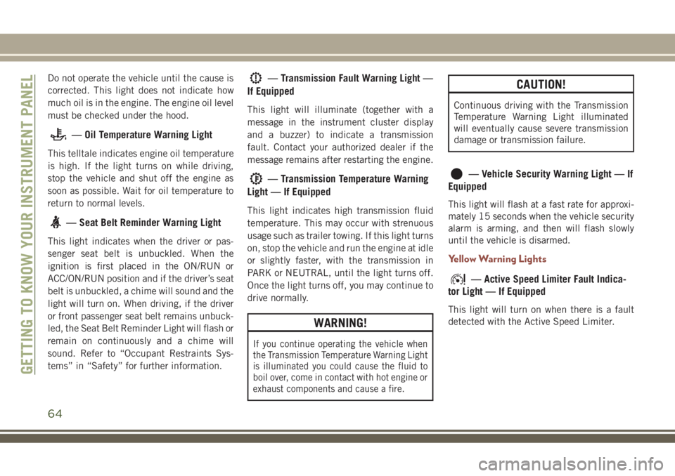
Do not operate the vehicle until the cause is
corrected. This light does not indicate how
much oil is in the engine. The engine oil level
must be checked under the hood.
— Oil Temperature Warning Light
This telltale indicates engine oil temperature
is high. If the light turns on while driving,
stop the vehicle and shut off the engine as
soon as possible. Wait for oil temperature to
return to normal levels.
— Seat Belt Reminder Warning Light
This light indicates when the driver or pas-
senger seat belt is unbuckled. When the
ignition is first placed in the ON/RUN or
ACC/ON/RUN position and if the driver’s seat
belt is unbuckled, a chime will sound and the
light will turn on. When driving, if the driver
or front passenger seat belt remains unbuck-
led, the Seat Belt Reminder Light will flash or
remain on continuously and a chime will
sound. Refer to “Occupant Restraints Sys-
tems” in “Safety” for further information.
— Transmission Fault Warning Light —
If Equipped
This light will illuminate (together with a
message in the instrument cluster display
and a buzzer) to indicate a transmission
fault. Contact your authorized dealer if the
message remains after restarting the engine.
— Transmission Temperature Warning
Light — If Equipped
This light indicates high transmission fluid
temperature. This may occur with strenuous
usage such as trailer towing. If this light turns
on, stop the vehicle and run the engine at idle
or slightly faster, with the transmission in
PARK or NEUTRAL, until the light turns off.
Once the light turns off, you may continue to
drive normally.
WARNING!
If you continue operating the vehicle when
the Transmission Temperature Warning Light
is illuminated you could cause the fluid to
boil over, come in contact with hot engine or
exhaust components and cause a fire.
CAUTION!
Continuous driving with the Transmission
Temperature Warning Light illuminated
will eventually cause severe transmission
damage or transmission failure.
— Vehicle Security Warning Light — If
Equipped
This light will flash at a fast rate for approxi-
mately 15 seconds when the vehicle security
alarm is arming, and then will flash slowly
until the vehicle is disarmed.
Yellow Warning Lights
— Active Speed Limiter Fault Indica-
tor Light — If Equipped
This light will turn on when there is a fault
detected with the Active Speed Limiter.
GETTING TO KNOW YOUR INSTRUMENT PANEL
64
Page 68 of 348
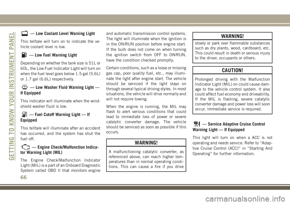
— Low Coolant Level Warning Light
This telltale will turn on to indicate the ve-
hicle coolant level is low.
— Low Fuel Warning Light
Depending on whether the tank size is 51L or
60L, the Low Fuel Indicator Light will turn on
when the fuel level goes below 1.5 gal (5.6L)
or 1.7 gal (6.6L) respectively.
— Low Washer Fluid Warning Light —
If Equipped
This indicator will illuminate when the wind-
shield washer fluid is low.
— Fuel Cutoff Warning Light — If
Equipped
This telltale will illuminate after an accident
has occurred, and the system has shut the
fuel off.
— Engine Check/Malfunction Indica-
tor Warning Light (MIL)
The Engine Check/Malfunction Indicator
Light (MIL) is a part of an Onboard Diagnostic
System called OBD II that monitors engineand automatic transmission control systems.
The light will illuminate when the ignition is
in the ON/RUN position before engine start.
If the bulb does not come on when turning
the ignition switch from OFF to ON/RUN,
have the condition checked promptly.
Certain conditions, such as a loose or missing
gas cap, poor quality fuel, etc., may illumi-
nate the light after engine start. The vehicle
should be serviced if the light stays on
through several typical driving styles. In most
situations, the vehicle will drive normally and
will not require towing.
When the engine is running, the MIL may
flash to alert serious conditions that could
lead to immediate loss of power or severe
catalytic converter damage. The vehicle
should be serviced as soon as possible if this
occurs.
WARNING!
A malfunctioning catalytic converter, as
referenced above, can reach higher tem-
peratures than in normal operating condi-
tions. This can cause a fire if you drive
WARNING!
slowly or park over flammable substances
such as dry plants, wood, cardboard, etc.
This could result in death or serious injury
to the driver, occupants or others.
CAUTION!
Prolonged driving with the Malfunction
Indicator Light (MIL) on could cause dam-
age to the vehicle control system. It also
could affect fuel economy and driveability.
If the MIL is flashing, severe catalytic
converter damage and power loss will soon
occur. Immediate service is required.
— Service Adaptive Cruise Control
Warning Light — If Equipped
This light will turn on when a ACC is not
operating and needs service. Refer to “Adap-
tive Cruise Control (ACC)” in “Starting And
Operating” for further information.
GETTING TO KNOW YOUR INSTRUMENT PANEL
66